wheel SUBARU LEGACY 1999 Service Repair Manual
[x] Cancel search | Manufacturer: SUBARU, Model Year: 1999, Model line: LEGACY, Model: SUBARU LEGACY 1999Pages: 1456, PDF Size: 59.93 MB
Page 935 of 1456
4) Within 0.5 seconds after the ABS warning light
goes out, depress the brake pedal and hold it
immediately after ignition switch is turned to ON.
CAUTION:
Do not depress the clutch pedal.
NOTE:
IWhen the ignition switch is set to on, the brake
pedal must not be depressed.
IEngine must not operate.
5) After completion of ABS sequence control, turn
ignition switch OFF.
2. OPERATIONAL GUIDELINES OF THE
ABS SEQUENCE CONTROL WITH
SELECT MONITOR
NOTE:
IIn the event of any trouble, the sequence con-
trol may not be operative. In such a case, activate
the sequence control, referring to ªOPERATIONAL
GUIDELINES OF THE ABS SEQUENCE CON-
TROL WITH DIAGNOSIS CONNECTORº.
IWhen the diagnosis terminal is connected to the
diagnosis connector, the sequence control will not
operate.
1) Connect select monitor to data link connector
beside driver's seat instrument panel lower cover.
2) Turn ignition switch ON.
3) Turn select monitor switch ON.
4) Put select monitor to {ABS/TCS} mode.
5) When {Function check sequence} is selected,
`ABS sequence control' will start.
6) The message `Press Brake Pedal Firmly' is dis-
played as follows:
(1) When using the brake tester, depress brake
pedal with braking force of 981 N (100 kg, 221
lb).
(2) When using the pressure gauge, depress
brake pedal so as to make the pressure gauge
indicate 3,432 kPa (35 kg/cm
2, 498 psi).
CAUTION:
Do not depress the clutch pedal.
7) When the message ªPress YESº is displayed,
press YES key.
8) Operation points will be displayed on select
monitor.
3. CONDITIONS FOR COMPLETION OF
ABS SEQUENCE CONTROL
When the following conditions develop, the ABS
sequence control stops and ABS operation is
returned to the normal control mode.
1) When the speed of at least one wheel reaches
10 km/h (6 MPH).
2) When terminal No. 3 or No. 6 are separated
from diagnosis terminals. (When select monitor is
not used.)
3) When the brake pedal is released during
sequence control and the braking lamp switch is
set to off.
4) When brake pedal is depressed after ignition
key is turned to ON, and before ABS warning light
goes out. (When select monitor is not used.)
5) When brake pedal is not depressed after igni-
tion key is turned to ON, and within 0.5 seconds
after ABS warning light goes out. (When select
monitor is not used.)
6) After completion of the sequence control.
7) When malfunction is detected. (When select
monitor is used.)
58
4-4[W15D2]SERVICE PROCEDURE
15. ABS Control Module and Hydraulic Control Unit (ABSCM&H/U)
Page 939 of 1456
![SUBARU LEGACY 1999 Service Repair Manual 6) Remove front drive shaft and housing and hub
assembly. <Ref. to 4-2 [W1A0].>
7) Remove tone wheel while removing hub from
housing and hub assembly. <Ref. to 4-2 [W1B0].>
CAUTION:
Be careful not to](/img/17/57435/w960_57435-938.png "SUBARU LEGACY 1999 Service Repair Manual 6) Remove front drive shaft and housing and hub
assembly. <Ref. to 4-2 [W1A0].>
7) Remove tone wheel while removing hub from
housing and hub assembly. <Ref. to 4-2 [W1B0].>
CAUTION:
Be careful not to")
6) Remove front drive shaft and housing and hub
assembly.
7) Remove tone wheel while removing hub from
housing and hub assembly.
CAUTION:
Be careful not to damage teeth faces of tone
wheel during removal.
G4M0444
B: INSPECTION WITH CIRCUIT
TESTER
16B1 : CHECK G SENSOR.
1) Turn ignition switch to OFF.
2) Remove G sensor from vehicle.
3) Connect connector to G sensor.
4) Turn ignition switch to ON.
5) Measure voltage between G sensor connector
terminals.
Connector & terminal
(P11) No. 2 (+) Ð No. 3 (þ)
B4M0915
:Is the voltage 2.3±0.2 V when G sen-
sor is horizontal?
: Go to step16B2.
: Replace G sensor.16B2 : CHECK G SENSOR.
Measure voltage between G sensor connector ter-
minals.
Connector & terminal
(P11) No. 2 (+) Ð No. 3 (þ)
B4M0917A
:Is the voltage 3.9±0.2 V when G sen-
sor is inclined forwards to 90É?
: Go to step16B3.
: Replace G sensor.
16B3 : CHECK G SENSOR.
Measure voltage between G sensor connector ter-
minals.
Connector & terminal
(P11) No. 2 (+) Ð No. 3 (þ)
B4M0918A
:Is the voltage 0.7±0.2 V when G sen-
sor is inclined backwards to 90É?
: G sensor is normal.
: Replace G sensor.
61
[W16B3]4-4SERVICE PROCEDURE
16. G Sensor
Page 940 of 1456
C: INSPECTION WITH SELECT
MONITOR
16C1 : CHECK G SENSOR.
1) Turn ignition switch to OFF.
2) Connect select monitor connector to data link
connector.
3) Turn select monitor into {ABS/TCS} mode.
4) Set the display in the {Current Data Display &
Save} mode.
5) Read the G sensor output voltage.
:Is the indicated reading 2.3±0.2 V
when the vehicle is in horizontal
position?
: Go to step16C2.
: Replace G sensor.
16C2 : CHECK G SENSOR.
1) Remove console box.
2) Remove G sensor from vehicle. (Do not discon-
nect connector.)
3) Read the select monitor display.
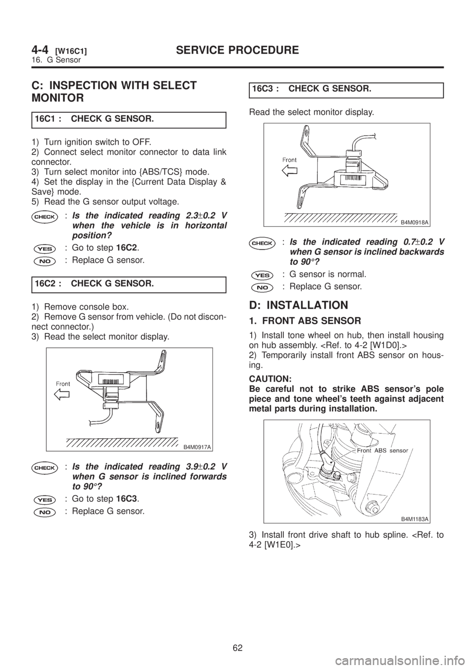
B4M0917A
:Is the indicated reading 3.9±0.2 V
when G sensor is inclined forwards
to 90É?
: Go to step16C3.
: Replace G sensor.16C3 : CHECK G SENSOR.
Read the select monitor display.
B4M0918A
:Is the indicated reading 0.7±0.2 V
when G sensor is inclined backwards
to 90É?
: G sensor is normal.
: Replace G sensor.
D: INSTALLATION
1. FRONT ABS SENSOR
1) Install tone wheel on hub, then install housing
on hub assembly.
2) Temporarily install front ABS sensor on hous-
ing.
CAUTION:
Be careful not to strike ABS sensor's pole
piece and tone wheel's teeth against adjacent
metal parts during installation.
B4M1183A
3) Install front drive shaft to hub spline.
62
4-4[W16C1]SERVICE PROCEDURE
16. G Sensor
Page 941 of 1456
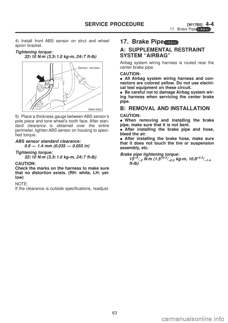
4) Install front ABS sensor on strut and wheel
apron bracket.
Tightening torque:
32
±10 N´m (3.3±1.0 kg-m, 24±7 ft-lb)
B4M1442A
5) Place a thickness gauge between ABS sensor's
pole piece and tone wheel's tooth face. After stan-
dard clearance is obtained over the entire
perimeter, tighten ABS sensor on housing to speci-
fied torque.
ABS sensor standard clearance:
0.9 Ð 1.4 mm (0.035 Ð 0.055 in)
Tightening torque:
32
±10 N´m (3.3±1.0 kg-m, 24±7 ft-lb)
CAUTION:
Check the marks on the harness to make sure
that no distortion exists. (RH: white, LH: yel-
low)
NOTE:
If the clearance is outside specifications, readjust.
17. Brake Pipe
A: SUPPLEMENTAL RESTRAINT
SYSTEM ªAIRBAGº
Airbag system wiring harness is routed near the
center brake pipe.
CAUTION:
IAll Airbag system wiring harness and con-
nectors are colored yellow. Do not use electri-
cal test equipment on these circuit.
IBe careful not to damage Airbag system wir-
ing harness when servicing the center brake
pipe.
B: REMOVAL AND INSTALLATION
CAUTION:
IWhen removing and installing the brake
pipe, make sure that it is not bent.
IAfter installing the brake pipe and hose,
bleed the air.
IAfter installing the brake hose, make sure
that it does not touch the tire or suspension
assembly, etc.
Brake pipe tightening torque:
15+3/þ2N´m (1.5+0.3/þ0.2kg-m, 10.8+2.2/þ1.4ft-lb)
63
[W17B0]4-4SERVICE PROCEDURE
17. Brake Pipe
Page 942 of 1456
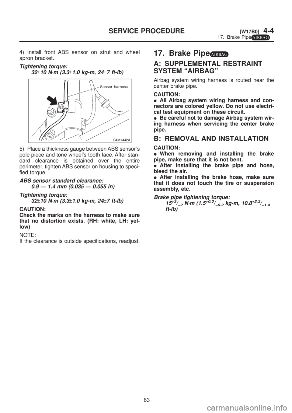
4) Install front ABS sensor on strut and wheel
apron bracket.
Tightening torque:
32
±10 N´m (3.3±1.0 kg-m, 24±7 ft-lb)
B4M1442A
5) Place a thickness gauge between ABS sensor's
pole piece and tone wheel's tooth face. After stan-
dard clearance is obtained over the entire
perimeter, tighten ABS sensor on housing to speci-
fied torque.
ABS sensor standard clearance:
0.9 Ð 1.4 mm (0.035 Ð 0.055 in)
Tightening torque:
32
±10 N´m (3.3±1.0 kg-m, 24±7 ft-lb)
CAUTION:
Check the marks on the harness to make sure
that no distortion exists. (RH: white, LH: yel-
low)
NOTE:
If the clearance is outside specifications, readjust.
17. Brake Pipe
A: SUPPLEMENTAL RESTRAINT
SYSTEM ªAIRBAGº
Airbag system wiring harness is routed near the
center brake pipe.
CAUTION:
IAll Airbag system wiring harness and con-
nectors are colored yellow. Do not use electri-
cal test equipment on these circuit.
IBe careful not to damage Airbag system wir-
ing harness when servicing the center brake
pipe.
B: REMOVAL AND INSTALLATION
CAUTION:
IWhen removing and installing the brake
pipe, make sure that it is not bent.
IAfter installing the brake pipe and hose,
bleed the air.
IAfter installing the brake hose, make sure
that it does not touch the tire or suspension
assembly, etc.
Brake pipe tightening torque:
15+3/þ2N´m (1.5+0.3/þ0.2kg-m, 10.8+2.2/þ1.4ft-lb)
63
[W17B0]4-4SERVICE PROCEDURE
17. Brake Pipe
Page 943 of 1456
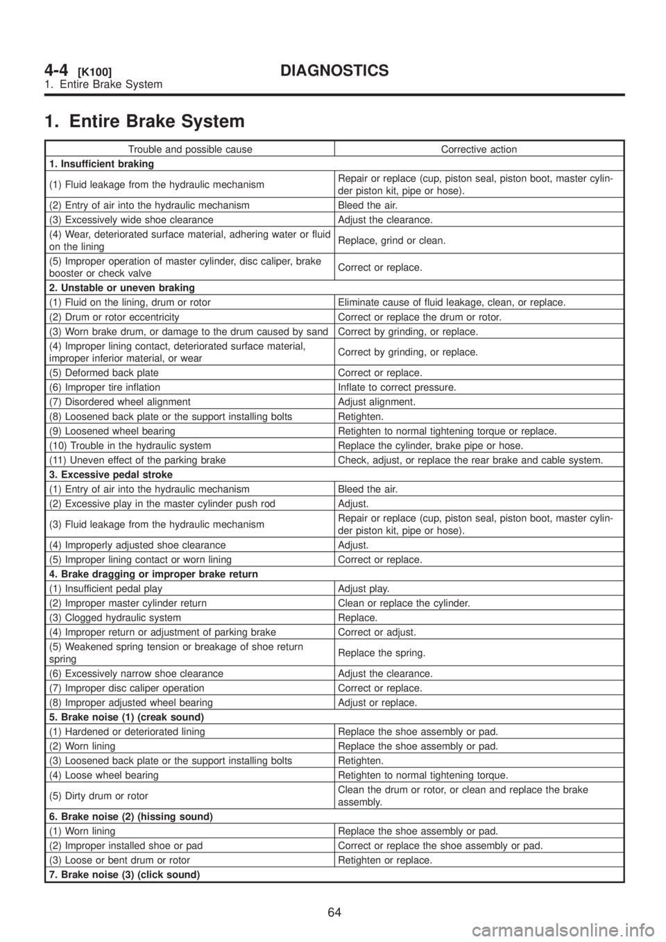
1. Entire Brake System
Trouble and possible cause Corrective action
1. Insufficient braking
(1) Fluid leakage from the hydraulic mechanismRepair or replace (cup, piston seal, piston boot, master cylin-
der piston kit, pipe or hose).
(2) Entry of air into the hydraulic mechanism Bleed the air.
(3) Excessively wide shoe clearance Adjust the clearance.
(4) Wear, deteriorated surface material, adhering water or fluid
on the liningReplace, grind or clean.
(5) Improper operation of master cylinder, disc caliper, brake
booster or check valveCorrect or replace.
2. Unstable or uneven braking
(1) Fluid on the lining, drum or rotor Eliminate cause of fluid leakage, clean, or replace.
(2) Drum or rotor eccentricity Correct or replace the drum or rotor.
(3) Worn brake drum, or damage to the drum caused by sand Correct by grinding, or replace.
(4) Improper lining contact, deteriorated surface material,
improper inferior material, or wearCorrect by grinding, or replace.
(5) Deformed back plate Correct or replace.
(6) Improper tire inflation Inflate to correct pressure.
(7) Disordered wheel alignment Adjust alignment.
(8) Loosened back plate or the support installing bolts Retighten.
(9) Loosened wheel bearing Retighten to normal tightening torque or replace.
(10) Trouble in the hydraulic system Replace the cylinder, brake pipe or hose.
(11) Uneven effect of the parking brake Check, adjust, or replace the rear brake and cable system.
3. Excessive pedal stroke
(1) Entry of air into the hydraulic mechanism Bleed the air.
(2) Excessive play in the master cylinder push rod Adjust.
(3) Fluid leakage from the hydraulic mechanismRepair or replace (cup, piston seal, piston boot, master cylin-
der piston kit, pipe or hose).
(4) Improperly adjusted shoe clearance Adjust.
(5) Improper lining contact or worn lining Correct or replace.
4. Brake dragging or improper brake return
(1) Insufficient pedal play Adjust play.
(2) Improper master cylinder return Clean or replace the cylinder.
(3) Clogged hydraulic system Replace.
(4) Improper return or adjustment of parking brake Correct or adjust.
(5) Weakened spring tension or breakage of shoe return
springReplace the spring.
(6) Excessively narrow shoe clearance Adjust the clearance.
(7) Improper disc caliper operation Correct or replace.
(8) Improper adjusted wheel bearing Adjust or replace.
5. Brake noise (1) (creak sound)
(1) Hardened or deteriorated lining Replace the shoe assembly or pad.
(2) Worn lining Replace the shoe assembly or pad.
(3) Loosened back plate or the support installing bolts Retighten.
(4) Loose wheel bearing Retighten to normal tightening torque.
(5) Dirty drum or rotorClean the drum or rotor, or clean and replace the brake
assembly.
6. Brake noise (2) (hissing sound)
(1) Worn lining Replace the shoe assembly or pad.
(2) Improper installed shoe or pad Correct or replace the shoe assembly or pad.
(3) Loose or bent drum or rotor Retighten or replace.
7. Brake noise (3) (click sound)
64
4-4[K100]DIAGNOSTICS
1. Entire Brake System
Page 1074 of 1456
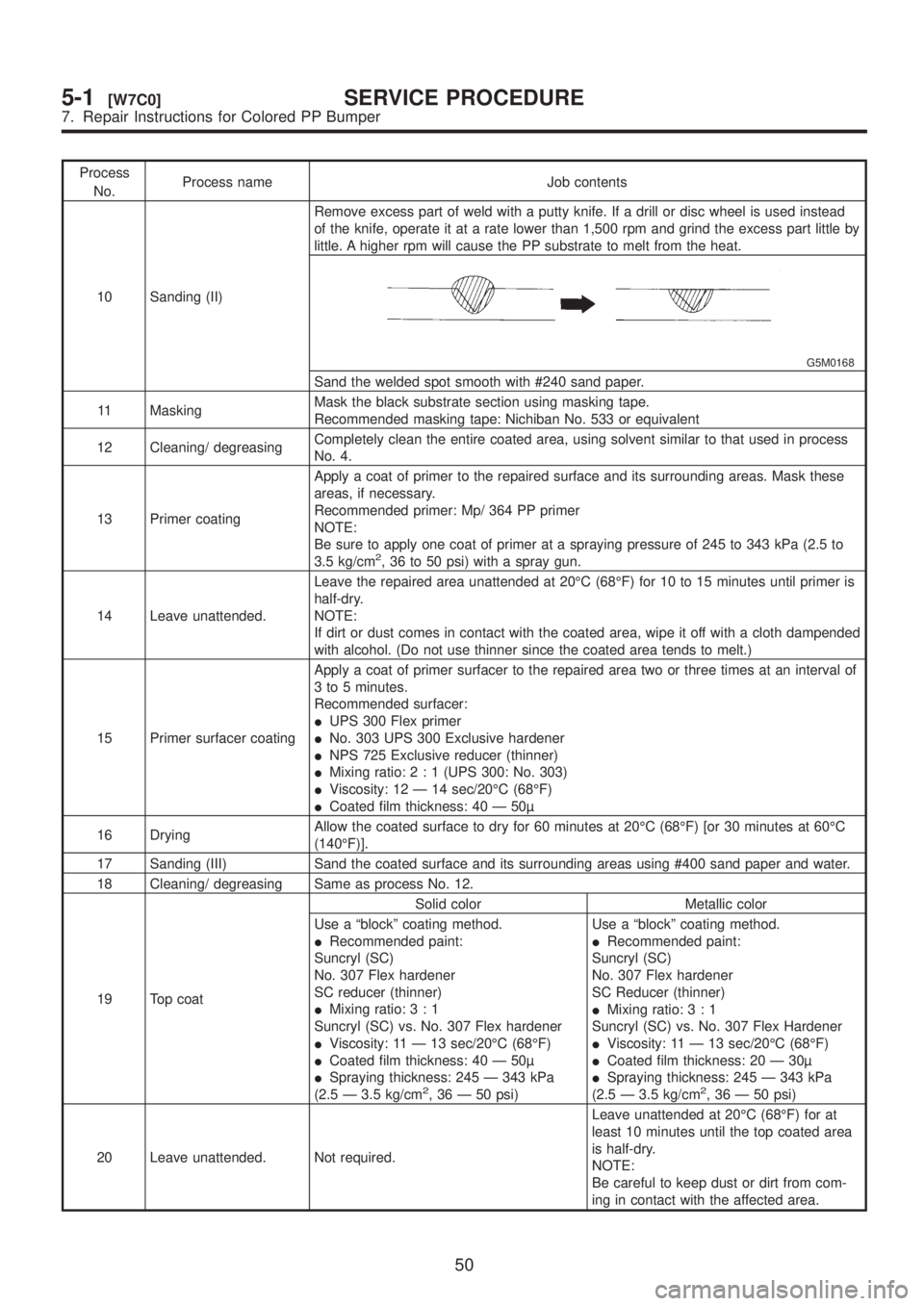
Process
No.Process name Job contents
10 Sanding (II)Remove excess part of weld with a putty knife. If a drill or disc wheel is used instead
of the knife, operate it at a rate lower than 1,500 rpm and grind the excess part little by
little. A higher rpm will cause the PP substrate to melt from the heat.
G5M0168
Sand the welded spot smooth with #240 sand paper.
11 MaskingMask the black substrate section using masking tape.
Recommended masking tape: Nichiban No. 533 or equivalent
12 Cleaning/ degreasingCompletely clean the entire coated area, using solvent similar to that used in process
No. 4.
13 Primer coatingApply a coat of primer to the repaired surface and its surrounding areas. Mask these
areas, if necessary.
Recommended primer: Mp/ 364 PP primer
NOTE:
Be sure to apply one coat of primer at a spraying pressure of 245 to 343 kPa (2.5 to
3.5 kg/cm
2, 36 to 50 psi) with a spray gun.
14 Leave unattended.Leave the repaired area unattended at 20ÉC (68ÉF) for 10 to 15 minutes until primer is
half-dry.
NOTE:
If dirt or dust comes in contact with the coated area, wipe it off with a cloth dampended
with alcohol. (Do not use thinner since the coated area tends to melt.)
15 Primer surfacer coatingApply a coat of primer surfacer to the repaired area two or three times at an interval of
3 to 5 minutes.
Recommended surfacer:
IUPS 300 Flex primer
INo. 303 UPS 300 Exclusive hardener
INPS 725 Exclusive reducer (thinner)
IMixing ratio:2:1(UPS 300: No. 303)
IViscosity: 12 Ð 14 sec/20ÉC (68ÉF)
ICoated film thickness: 40 Ð 50
16 DryingAllow the coated surface to dry for 60 minutes at 20ÉC (68ÉF) [or 30 minutes at 60ÉC
(140ÉF)].
17 Sanding (III) Sand the coated surface and its surrounding areas using #400 sand paper and water.
18 Cleaning/ degreasing Same as process No. 12.
19 Top coatSolid color Metallic color
Use a ªblockº coating method.
IRecommended paint:
Suncryl (SC)
No. 307 Flex hardener
SC reducer (thinner)
IMixing ratio:3:1
Suncryl (SC) vs. No. 307 Flex hardener
IViscosity: 11 Ð 13 sec/20ÉC (68ÉF)
ICoated film thickness: 40 Ð 50
ISpraying thickness: 245 Ð 343 kPa
(2.5 Ð 3.5 kg/cm
2, 36 Ð 50 psi)Use a ªblockº coating method.
IRecommended paint:
Suncryl (SC)
No. 307 Flex hardener
SC Reducer (thinner)
IMixing ratio:3:1
Suncryl (SC) vs. No. 307 Flex Hardener
IViscosity: 11 Ð 13 sec/20ÉC (68ÉF)
ICoated film thickness: 20 Ð 30
ISpraying thickness: 245 Ð 343 kPa
(2.5 Ð 3.5 kg/cm2, 36 Ð 50 psi)
20 Leave unattended. Not required.Leave unattended at 20ÉC (68ÉF) for at
least 10 minutes until the top coated area
is half-dry.
NOTE:
Be careful to keep dust or dirt from com-
ing in contact with the affected area.
50
5-1[W7C0]SERVICE PROCEDURE
7. Repair Instructions for Colored PP Bumper
Page 1169 of 1456
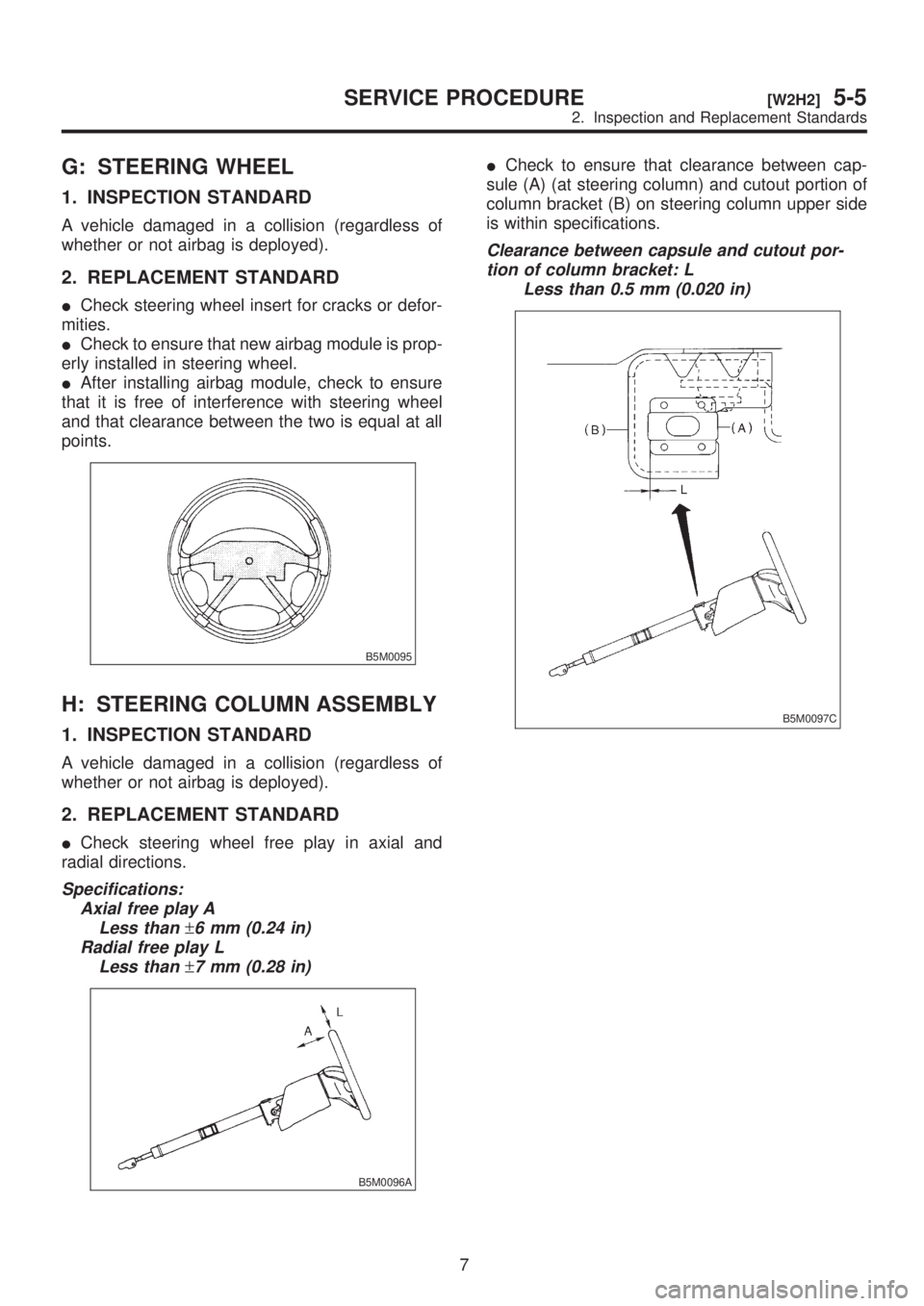
G: STEERING WHEEL
1. INSPECTION STANDARD
A vehicle damaged in a collision (regardless of
whether or not airbag is deployed).
2. REPLACEMENT STANDARD
ICheck steering wheel insert for cracks or defor-
mities.
ICheck to ensure that new airbag module is prop-
erly installed in steering wheel.
IAfter installing airbag module, check to ensure
that it is free of interference with steering wheel
and that clearance between the two is equal at all
points.
B5M0095
H: STEERING COLUMN ASSEMBLY
1. INSPECTION STANDARD
A vehicle damaged in a collision (regardless of
whether or not airbag is deployed).
2. REPLACEMENT STANDARD
ICheck steering wheel free play in axial and
radial directions.
Specifications:
Axial free play A
Less than
±6 mm (0.24 in)
Radial free play L
Less than
±7 mm (0.28 in)
B5M0096A
ICheck to ensure that clearance between cap-
sule (A) (at steering column) and cutout portion of
column bracket (B) on steering column upper side
is within specifications.
Clearance between capsule and cutout por-
tion of column bracket: L
Less than 0.5 mm (0.020 in)
B5M0097C
7
[W2H2]5-5SERVICE PROCEDURE
2. Inspection and Replacement Standards
Page 1172 of 1456
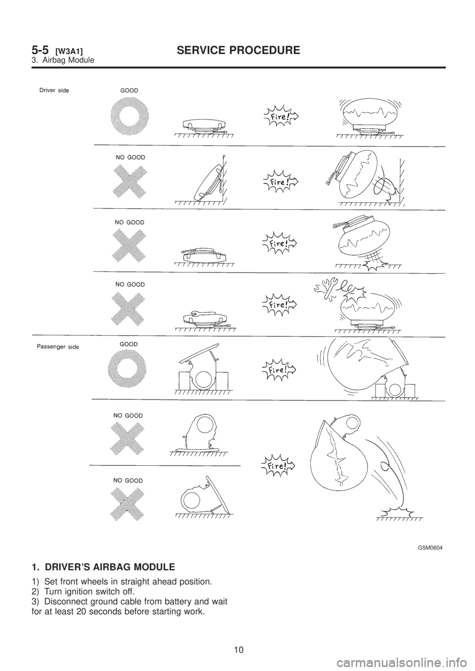
G5M0604
1. DRIVER'S AIRBAG MODULE
1) Set front wheels in straight ahead position.
2) Turn ignition switch off.
3) Disconnect ground cable from battery and wait
for at least 20 seconds before starting work.
10
5-5[W3A1]SERVICE PROCEDURE
3. Airbag Module
Page 1177 of 1456
![SUBARU LEGACY 1999 Service Repair Manual 6. Combination Switch
A: REMOVAL
1) Turn ignition switch off.
2) Disconnect ground cable from battery and wait
for at least 20 seconds before starting work.
3) Remove lower cover. <Ref. to 5-4 [W1A0].](/img/17/57435/w960_57435-1176.png "SUBARU LEGACY 1999 Service Repair Manual 6. Combination Switch
A: REMOVAL
1) Turn ignition switch off.
2) Disconnect ground cable from battery and wait
for at least 20 seconds before starting work.
3) Remove lower cover. <Ref. to 5-4 [W1A0].")
6. Combination Switch
A: REMOVAL
1) Turn ignition switch off.
2) Disconnect ground cable from battery and wait
for at least 20 seconds before starting work.
3) Remove lower cover.
Disconnect airbag connector (AB3) and (AB8)
below steering column.
CAUTION:
Do not reconnect airbag connector at steering
column until combination switch is securely re-
installed.
G5M0312
4) Disconnect combination switch connectors
from body harness connector.
5) Set front wheels in straight ahead position.
Using TORX
TBIT T30, remove two TORXTbolts.
H5M0662A
6) Disconnect airbag connector on back of airbag
module.
module, and place it with pad side facing upward.
H5M0664
7) Using steering puller, remove steering wheel.
CAUTION:
Do not allow connector to interfere when
removing steering wheel.
G5M0332
8) Remove steering column covers.
9) Removing two retaining screws, remove combi-
nation switch.
B5M0106
B: ADJUSTMENT
1. CENTERING ROLL CONNECTOR
Before installing steering wheel, make sure to cen-
ter roll connector built into combination switch.
1) Make sure that front wheels are positioned
straight ahead.
2) Install steering gearbox, steering shaft and
combination switch properly. Turn roll connector
pin (A) clockwise until it stops.
3) Then, back off roll connector pin (A) approxi-
mately 2.65 turns until ªGº marks aligned.
B5M0457A
15
[W6B1]5-5SERVICE PROCEDURE
6. Combination Switch