differential SUBARU LEGACY 1999 Service User Guide
[x] Cancel search | Manufacturer: SUBARU, Model Year: 1999, Model line: LEGACY, Model: SUBARU LEGACY 1999Pages: 1456, PDF Size: 59.93 MB
Page 475 of 1456
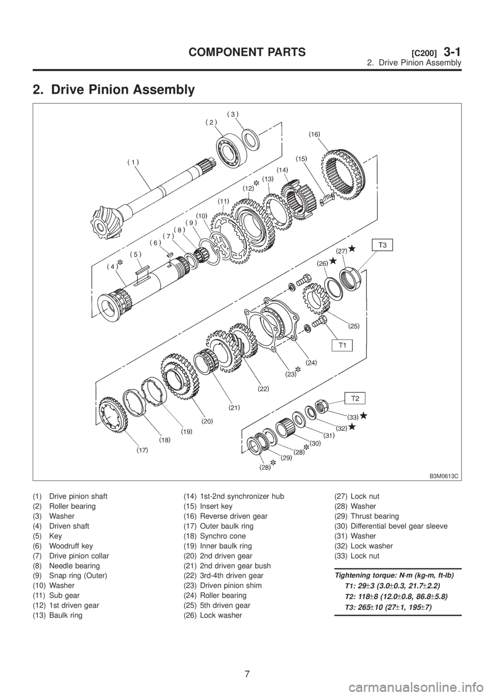
2. Drive Pinion Assembly
B3M0613C
(1) Drive pinion shaft
(2) Roller bearing
(3) Washer
(4) Driven shaft
(5) Key
(6) Woodruff key
(7) Drive pinion collar
(8) Needle bearing
(9) Snap ring (Outer)
(10) Washer
(11) Sub gear
(12) 1st driven gear
(13) Baulk ring(14) 1st-2nd synchronizer hub
(15) Insert key
(16) Reverse driven gear
(17) Outer baulk ring
(18) Synchro cone
(19) Inner baulk ring
(20) 2nd driven gear
(21) 2nd driven gear bush
(22) 3rd-4th driven gear
(23) Driven pinion shim
(24) Roller bearing
(25) 5th driven gear
(26) Lock washer(27) Lock nut
(28) Washer
(29) Thrust bearing
(30) Differential bevel gear sleeve
(31) Washer
(32) Lock washer
(33) Lock nut
Tightening torque: N´m (kg-m, ft-lb)
T1:
29±3 (3.0±0.3, 21.7±2.2)
T2:11 8±8 (12.0±0.8, 86.8±5.8)
T3:265±10 (27±1, 195±7)
7
[C200]3-1COMPONENT PARTS
2. Drive Pinion Assembly
Page 479 of 1456
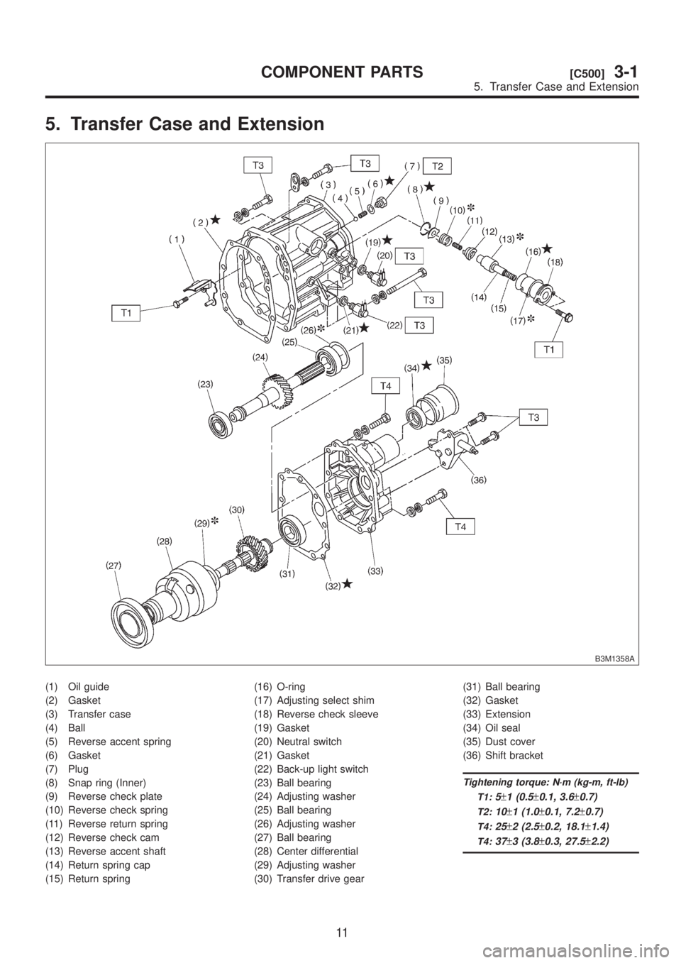
5. Transfer Case and Extension
B3M1358A
(1) Oil guide
(2) Gasket
(3) Transfer case
(4) Ball
(5) Reverse accent spring
(6) Gasket
(7) Plug
(8) Snap ring (Inner)
(9) Reverse check plate
(10) Reverse check spring
(11) Reverse return spring
(12) Reverse check cam
(13) Reverse accent shaft
(14) Return spring cap
(15) Return spring(16) O-ring
(17) Adjusting select shim
(18) Reverse check sleeve
(19) Gasket
(20) Neutral switch
(21) Gasket
(22) Back-up light switch
(23) Ball bearing
(24) Adjusting washer
(25) Ball bearing
(26) Adjusting washer
(27) Ball bearing
(28) Center differential
(29) Adjusting washer
(30) Transfer drive gear(31) Ball bearing
(32) Gasket
(33) Extension
(34) Oil seal
(35) Dust cover
(36) Shift bracket
Tightening torque: N´m (kg-m, ft-lb)
T1:
5±1 (0.5±0.1, 3.6±0.7)
T2:10±1 (1.0±0.1, 7.2±0.7)
T4:25±2 (2.5±0.2, 18.1±1.4)
T4:37±3 (3.8±0.3, 27.5±2.2)
11
[C500]3-1COMPONENT PARTS
5. Transfer Case and Extension
Page 480 of 1456
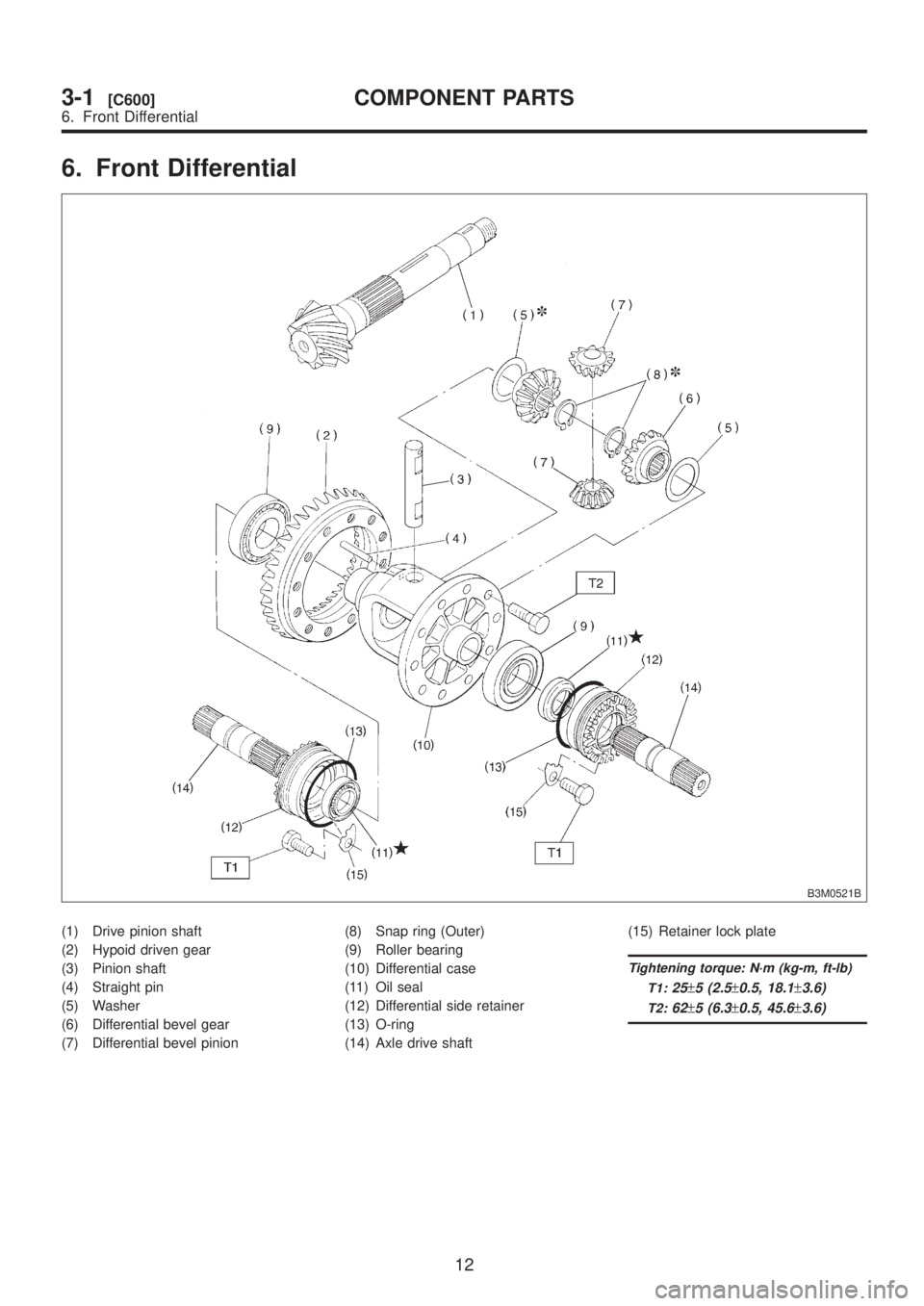
6. Front Differential
B3M0521B
(1) Drive pinion shaft
(2) Hypoid driven gear
(3) Pinion shaft
(4) Straight pin
(5) Washer
(6) Differential bevel gear
(7) Differential bevel pinion(8) Snap ring (Outer)
(9) Roller bearing
(10) Differential case
(11) Oil seal
(12) Differential side retainer
(13) O-ring
(14) Axle drive shaft(15) Retainer lock plate
Tightening torque: N´m (kg-m, ft-lb)
T1:
25±5 (2.5±0.5, 18.1±3.6)
T2:62±5 (6.3±0.5, 45.6±3.6)
12
3-1[C600]COMPONENT PARTS
6. Front Differential
Page 482 of 1456
IIf the gap between the end faces of the ring and
the gear splined part is excessively small when the
ring is pressed against the cone.
Clearance (A):
0.5 Ð 1.0 mm (0.020 Ð 0.040 in)
S3M0188
IWhen the contact surface of the synchronizer
ring insert is scored or abnormally worn down.
5) Shifting insert
Replace the insert if deformed, excessively worn,
or defective in any way.
S3M0189
6) Oil seal
Replace the oil seal if the lip is deformed,
hardened, damaged, worn, or defective in any way.
7) O-ring
Replace the O-ring if the sealing face is deformed,
hardened, damaged, worn, or defective in any way.
8) Gearshift mechanism
Repair or replace the gearshift mechanism if
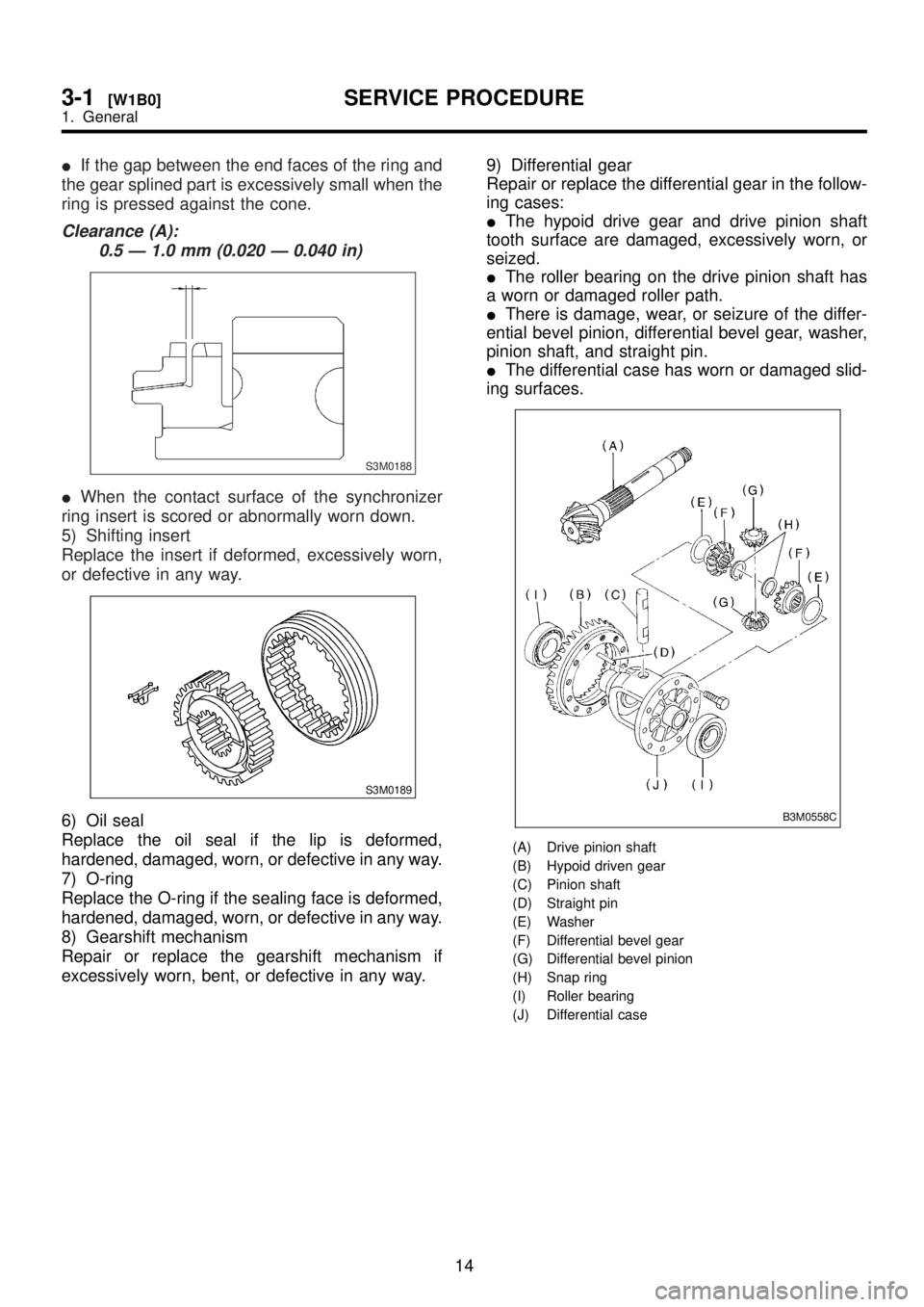
excessively worn, bent, or defective in any way.9) Differential gear
Repair or replace the differential gear in the follow-
ing cases:
IThe hypoid drive gear and drive pinion shaft
tooth surface are damaged, excessively worn, or
seized.
IThe roller bearing on the drive pinion shaft has
a worn or damaged roller path.
IThere is damage, wear, or seizure of the differ-
ential bevel pinion, differential bevel gear, washer,
pinion shaft, and straight pin.
IThe differential case has worn or damaged slid-
ing surfaces.B3M0558C
(A) Drive pinion shaft
(B) Hypoid driven gear
(C) Pinion shaft
(D) Straight pin
(E) Washer
(F) Differential bevel gear
(G) Differential bevel pinion
(H) Snap ring
(I) Roller bearing
(J) Differential case
14
3-1[W1B0]SERVICE PROCEDURE
1. General
Page 483 of 1456
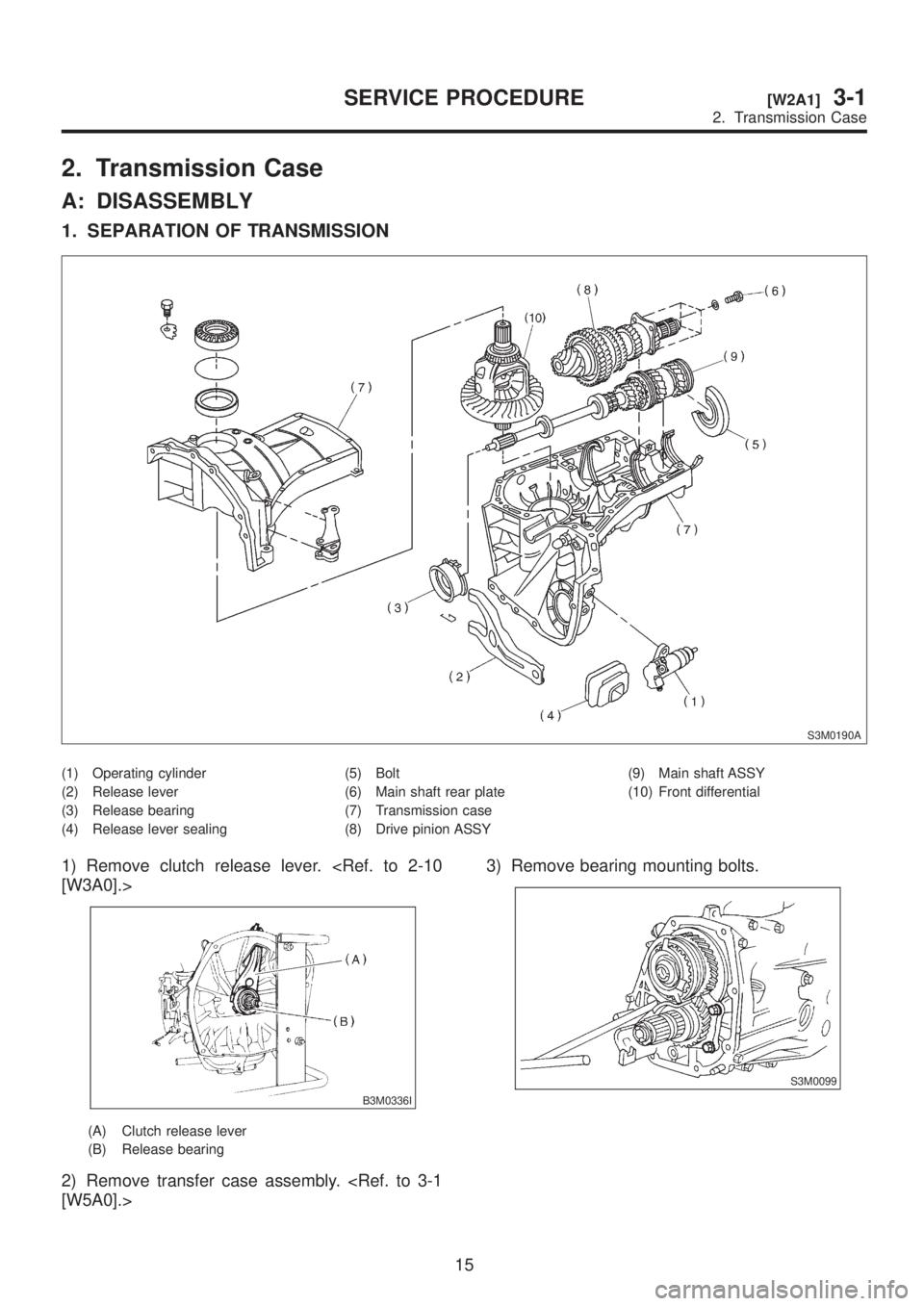
2. Transmission Case
A: DISASSEMBLY
1. SEPARATION OF TRANSMISSION
S3M0190A
(1) Operating cylinder
(2) Release lever
(3) Release bearing
(4) Release lever sealing(5) Bolt
(6) Main shaft rear plate
(7) Transmission case
(8) Drive pinion ASSY(9) Main shaft ASSY
(10) Front differential
1) Remove clutch release lever.
B3M0336I
(A) Clutch release lever
(B) Release bearing
2) Remove transfer case assembly.
S3M0099
15
[W2A1]3-1SERVICE PROCEDURE
2. Transmission Case
Page 484 of 1456
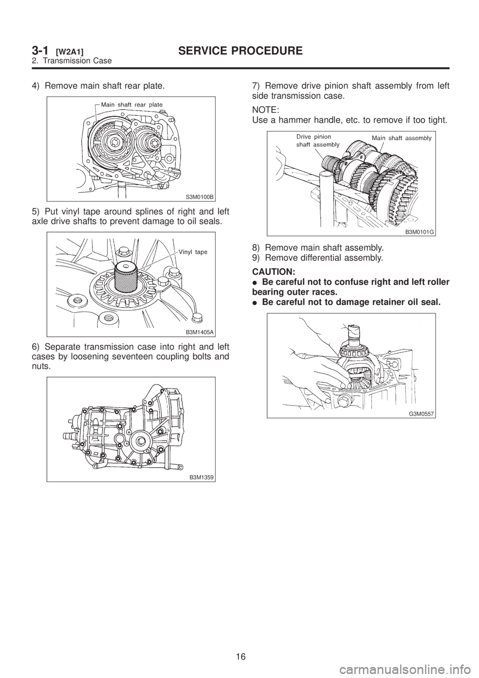
4) Remove main shaft rear plate.
S3M0100B
5) Put vinyl tape around splines of right and left
axle drive shafts to prevent damage to oil seals.
B3M1405A
6) Separate transmission case into right and left
cases by loosening seventeen coupling bolts and
nuts.
B3M1359
7) Remove drive pinion shaft assembly from left
side transmission case.
NOTE:
Use a hammer handle, etc. to remove if too tight.
B3M0101G
8) Remove main shaft assembly.
9) Remove differential assembly.
CAUTION:
IBe careful not to confuse right and left roller
bearing outer races.
IBe careful not to damage retainer oil seal.
G3M0557
16
3-1[W2A1]SERVICE PROCEDURE
2. Transmission Case
Page 486 of 1456
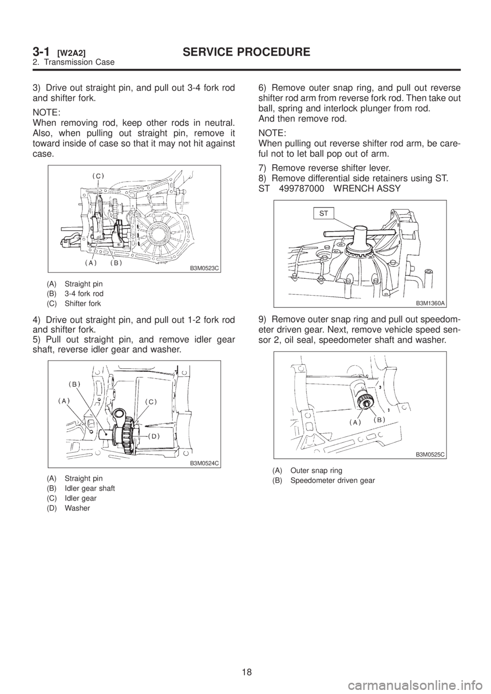
3) Drive out straight pin, and pull out 3-4 fork rod
and shifter fork.
NOTE:
When removing rod, keep other rods in neutral.
Also, when pulling out straight pin, remove it
toward inside of case so that it may not hit against
case.
B3M0523C
(A) Straight pin
(B) 3-4 fork rod
(C) Shifter fork
4) Drive out straight pin, and pull out 1-2 fork rod
and shifter fork.
5) Pull out straight pin, and remove idler gear
shaft, reverse idler gear and washer.
B3M0524C
(A) Straight pin
(B) Idler gear shaft
(C) Idler gear
(D) Washer
6) Remove outer snap ring, and pull out reverse
shifter rod arm from reverse fork rod. Then take out
ball, spring and interlock plunger from rod.
And then remove rod.
NOTE:
When pulling out reverse shifter rod arm, be care-
ful not to let ball pop out of arm.
7) Remove reverse shifter lever.
8) Remove differential side retainers using ST.
ST 499787000 WRENCH ASSY
B3M1360A
9) Remove outer snap ring and pull out speedom-
eter driven gear. Next, remove vehicle speed sen-
sor 2, oil seal, speedometer shaft and washer.
B3M0525C
(A) Outer snap ring
(B) Speedometer driven gear
18
3-1[W2A2]SERVICE PROCEDURE
2. Transmission Case
Page 490 of 1456
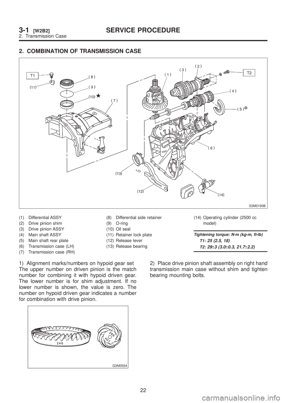
2. COMBINATION OF TRANSMISSION CASE
S3M0190B
(1) Differential ASSY
(2) Drive pinion shim
(3) Drive pinion ASSY
(4) Main shaft ASSY
(5) Main shaft rear plate
(6) Transmission case (LH)
(7) Transmission case (RH)(8) Differential side retainer
(9) O-ring
(10) Oil seal
(11) Retainer lock plate
(12) Release lever
(13) Release bearing(14) Operating cylinder (2500 cc
model)
Tightening torque: N´m (kg-m, ft-lb)
T1:
25 (2.5, 18)
T2:29±3 (3.0±0.3, 21.7±2.2)
1) Alignment marks/numbers on hypoid gear set
The upper number on driven pinion is the match
number for combining it with hypoid driven gear.
The lower number is for shim adjustment. If no
lower number is shown, the value is zero. The
number on hypoid driven gear indicates a number
for combination with drive pinion.
G3M0554
2) Place drive pinion shaft assembly on right hand
transmission main case without shim and tighten
bearing mounting bolts.
22
3-1[W2B2]SERVICE PROCEDURE
2. Transmission Case
Page 491 of 1456
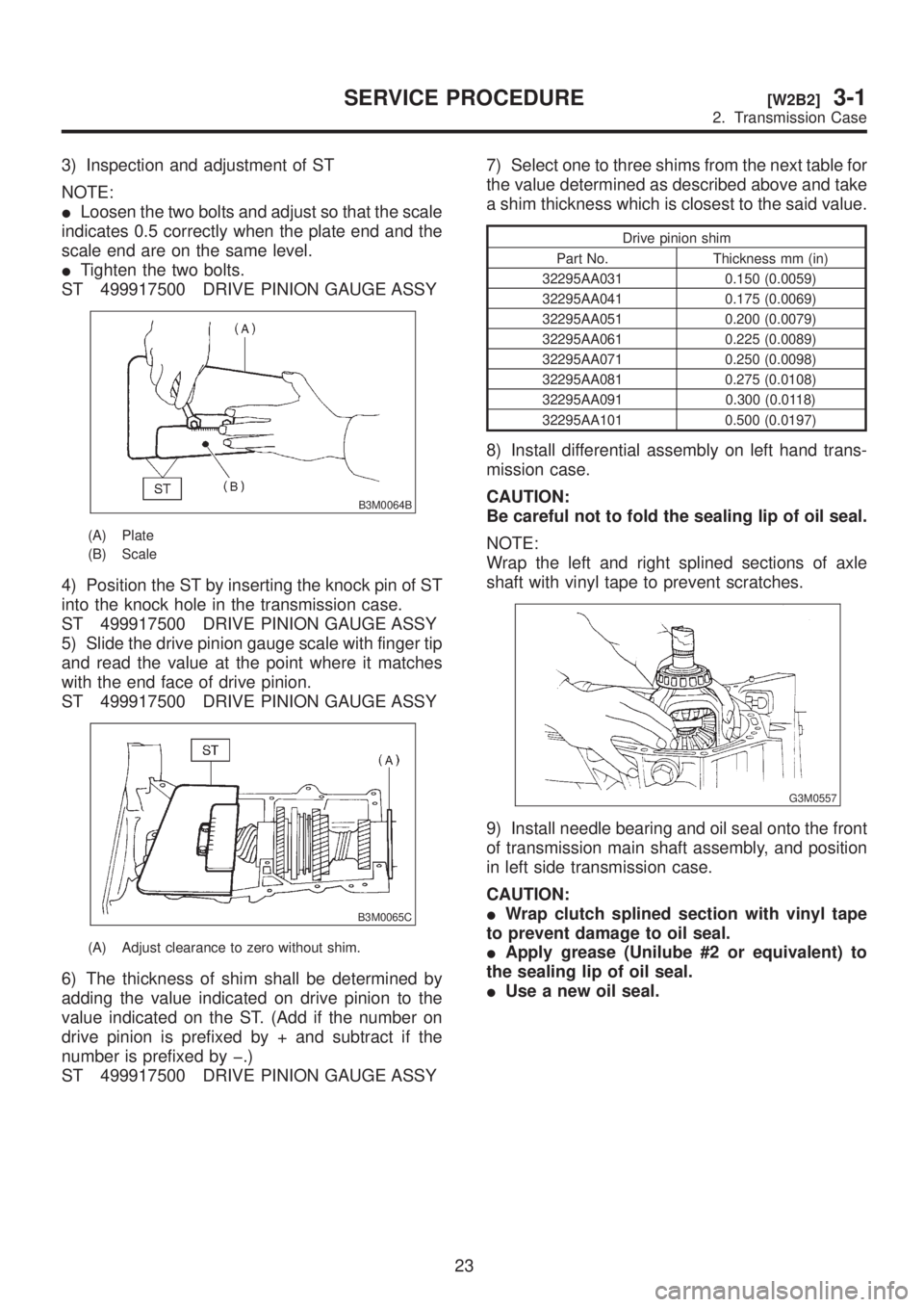
3) Inspection and adjustment of ST
NOTE:
ILoosen the two bolts and adjust so that the scale
indicates 0.5 correctly when the plate end and the
scale end are on the same level.
ITighten the two bolts.
ST 499917500 DRIVE PINION GAUGE ASSY
B3M0064B
(A) Plate
(B) Scale
4) Position the ST by inserting the knock pin of ST
into the knock hole in the transmission case.
ST 499917500 DRIVE PINION GAUGE ASSY
5) Slide the drive pinion gauge scale with finger tip
and read the value at the point where it matches
with the end face of drive pinion.
ST 499917500 DRIVE PINION GAUGE ASSY
B3M0065C
(A) Adjust clearance to zero without shim.
6) The thickness of shim shall be determined by
adding the value indicated on drive pinion to the
value indicated on the ST. (Add if the number on
drive pinion is prefixed by + and subtract if the
number is prefixed by þ.)
ST 499917500 DRIVE PINION GAUGE ASSY7) Select one to three shims from the next table for
the value determined as described above and take
a shim thickness which is closest to the said value.
Drive pinion shim
Part No. Thickness mm (in)
32295AA031 0.150 (0.0059)
32295AA041 0.175 (0.0069)
32295AA051 0.200 (0.0079)
32295AA061 0.225 (0.0089)
32295AA071 0.250 (0.0098)
32295AA081 0.275 (0.0108)
32295AA091 0.300 (0.0118)
32295AA101 0.500 (0.0197)
8) Install differential assembly on left hand trans-
mission case.
CAUTION:
Be careful not to fold the sealing lip of oil seal.
NOTE:
Wrap the left and right splined sections of axle
shaft with vinyl tape to prevent scratches.
G3M0557
9) Install needle bearing and oil seal onto the front
of transmission main shaft assembly, and position
in left side transmission case.
CAUTION:
IWrap clutch splined section with vinyl tape
to prevent damage to oil seal.
IApply grease (Unilube #2 or equivalent) to
the sealing lip of oil seal.
IUse a new oil seal.
23
[W2B2]3-1SERVICE PROCEDURE
2. Transmission Case
Page 497 of 1456
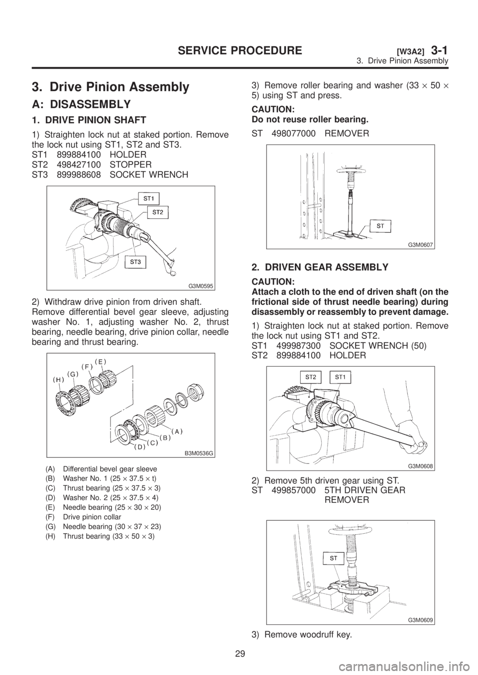
3. Drive Pinion Assembly
A: DISASSEMBLY
1. DRIVE PINION SHAFT
1) Straighten lock nut at staked portion. Remove
the lock nut using ST1, ST2 and ST3.
ST1 899884100 HOLDER
ST2 498427100 STOPPER
ST3 899988608 SOCKET WRENCH
G3M0595
2) Withdraw drive pinion from driven shaft.
Remove differential bevel gear sleeve, adjusting
washer No. 1, adjusting washer No. 2, thrust
bearing, needle bearing, drive pinion collar, needle
bearing and thrust bearing.
B3M0536G
(A) Differential bevel gear sleeve
(B) Washer No. 1 (25´37.5´t)
(C) Thrust bearing (25´37.5´3)
(D) Washer No. 2 (25´37.5´4)
(E) Needle bearing (25´30´20)
(F) Drive pinion collar
(G) Needle bearing (30´37´23)
(H) Thrust bearing (33´50´3)
3) Remove roller bearing and washer (33´50´
5) using ST and press.
CAUTION:
Do not reuse roller bearing.
ST 498077000 REMOVER
G3M0607
2. DRIVEN GEAR ASSEMBLY
CAUTION:
Attach a cloth to the end of driven shaft (on the
frictional side of thrust needle bearing) during
disassembly or reassembly to prevent damage.
1) Straighten lock nut at staked portion. Remove
the lock nut using ST1 and ST2.
ST1 499987300 SOCKET WRENCH (50)
ST2 899884100 HOLDER
G3M0608
2) Remove 5th driven gear using ST.
ST 499857000 5TH DRIVEN GEAR
REMOVER
G3M0609
3) Remove woodruff key.
29
[W3A2]3-1SERVICE PROCEDURE
3. Drive Pinion Assembly