differential SUBARU LEGACY 1999 Service Owner's Manual
[x] Cancel search | Manufacturer: SUBARU, Model Year: 1999, Model line: LEGACY, Model: SUBARU LEGACY 1999Pages: 1456, PDF Size: 59.93 MB
Page 501 of 1456
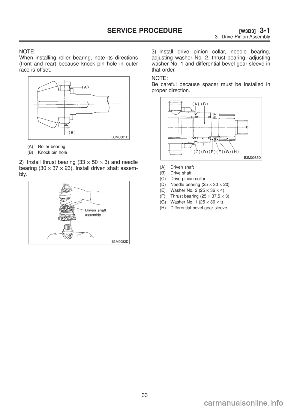
NOTE:
When installing roller bearing, note its directions
(front and rear) because knock pin hole in outer
race is offset.
B3M0081D
(A) Roller bearing
(B) Knock pin hole
2) Install thrust bearing (33´50´3) and needle
bearing (30´37´23). Install driven shaft assem-
bly.
B3M0082D
3) Install drive pinion collar, needle bearing,
adjusting washer No. 2, thrust bearing, adjusting
washer No. 1 and differential bevel gear sleeve in
that order.
NOTE:
Be careful because spacer must be installed in
proper direction.
B3M0083D
(A) Driven shaft
(B) Drive shaft
(C) Drive pinion collar
(D) Needle bearing (25´30´20)
(E) Washer No. 2 (25´36´4)
(F) Thrust bearing (25´37.5´3)
(G) Washer No. 1 (25´36´t)
(H) Differential bevel gear sleeve
33
[W3B3]3-1SERVICE PROCEDURE
3. Drive Pinion Assembly
Page 517 of 1456
2) Install reverse check sleeve assembly to trans-
fer case.
Tightening torque:
6.4
±0.5 N´m (0.65±0.05 kg-m, 4.7±0.4 ft-lb)
B3M1377
3) Install ball, reverse accent spring, washer and
plug to transfer case.
Tightening torque:
10
±1 N´m (1.0±0.1 kg-m, 7.2±0.7 ft-lb)
B3M1376
4. TRANSFER DRIVEN GEAR
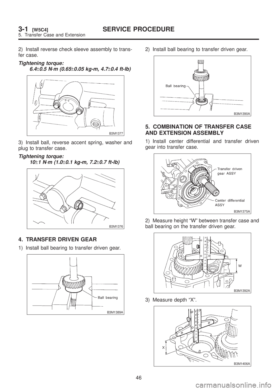
1) Install ball bearing to transfer driven gear.
B3M1389A
2) Install ball bearing to transfer driven gear.
B3M1390A
5. COMBINATION OF TRANSFER CASE
AND EXTENSION ASSEMBLY
1) Install center differential and transfer driven
gear into transfer case.
B3M1375A
2) Measure height ªWº between transfer case and
ball bearing on the transfer driven gear.
B3M1392A
3) Measure depth ªXº.
B3M1406A
46
3-1[W5C4]SERVICE PROCEDURE
5. Transfer Case and Extension
Page 518 of 1456
![SUBARU LEGACY 1999 Service Owners Manual 4) Calculate space ªYº using the following equa-
tion: Y=XþW+0.24 mm (0.0094 in) [Thickness
of gasket]
5) Select suitable washer in the following table:
Standard clearance between thrust washer
and](/img/17/57435/w960_57435-517.png "SUBARU LEGACY 1999 Service Owners Manual 4) Calculate space ªYº using the following equa-
tion: Y=XþW+0.24 mm (0.0094 in) [Thickness
of gasket]
5) Select suitable washer in the following table:
Standard clearance between thrust washer
and")
4) Calculate space ªYº using the following equa-
tion: Y=XþW+0.24 mm (0.0094 in) [Thickness
of gasket]
5) Select suitable washer in the following table:
Standard clearance between thrust washer
and ball bearing:
0.05 Ð 0.30 mm (0.0020 Ð 0.0118 in)
Space ªYº mm (in)Thrust washer (52´61´t)
Part No.Thickness
mm (in)
0.55 Ð 0.79
(0.0217 Ð 0.0311)803052021 0.50 (0.0197)
0.80 Ð 1.04
(0.0315 Ð 0.0409)803052022 0.75 (0.0295)
1.05 Ð 1.30
(0.0413 Ð 0.0512)803052023 1.00 (0.0394)
6) Fit thrust washers on transfer drive shaft.
7) Measure depth ªSº between transfer case and
center differential.
ST 398643600 GAUGE
B3M1407A
8) Measure depth ªTº between extension case
and transfer drive grar.
ST 398643600 GAUGE
B3M1395A
9) Calculate space ªUº using the following equa-
tion:U=S+T-0.24 mm (0.0094 in) [Thickness
of gasket]
10) Select suitable washer inthe following table:
Standard clearance:
0.15 Ð 0.35 mm (0.0059 Ð 0.0138 in)
Thrust washer
Part No. Thickness mm (in)
803036050 0.9 (0.035)
803036054 1.0 (0.039)
803036051 1.1 (0.043)
803036055 1.2 (0.047)
803036052 1.3 (0.051)
803036056 1.4 (0.055)
803036053 1.5 (0.059)
803036057 1.6 (0.063)
803036058 1.7 (0.067)
11) Fit thrust washer on center differential.
12) Install extension assembly into transfer case.
Tightening torque:
37
±3 N´m (3.8±0.3 kg-m, 27.5±2.2 ft-lb)
B3M0052A
D: INSTALLATION
1) Install shifter arm to transfer case.
B3M1396
2) Hang the shifter arm on the 3rd-4th fork rod.
B3M1397A
47
[W5D0]3-1SERVICE PROCEDURE
5. Transfer Case and Extension
Page 520 of 1456
6. Front Differential
A: DISASSEMBLY
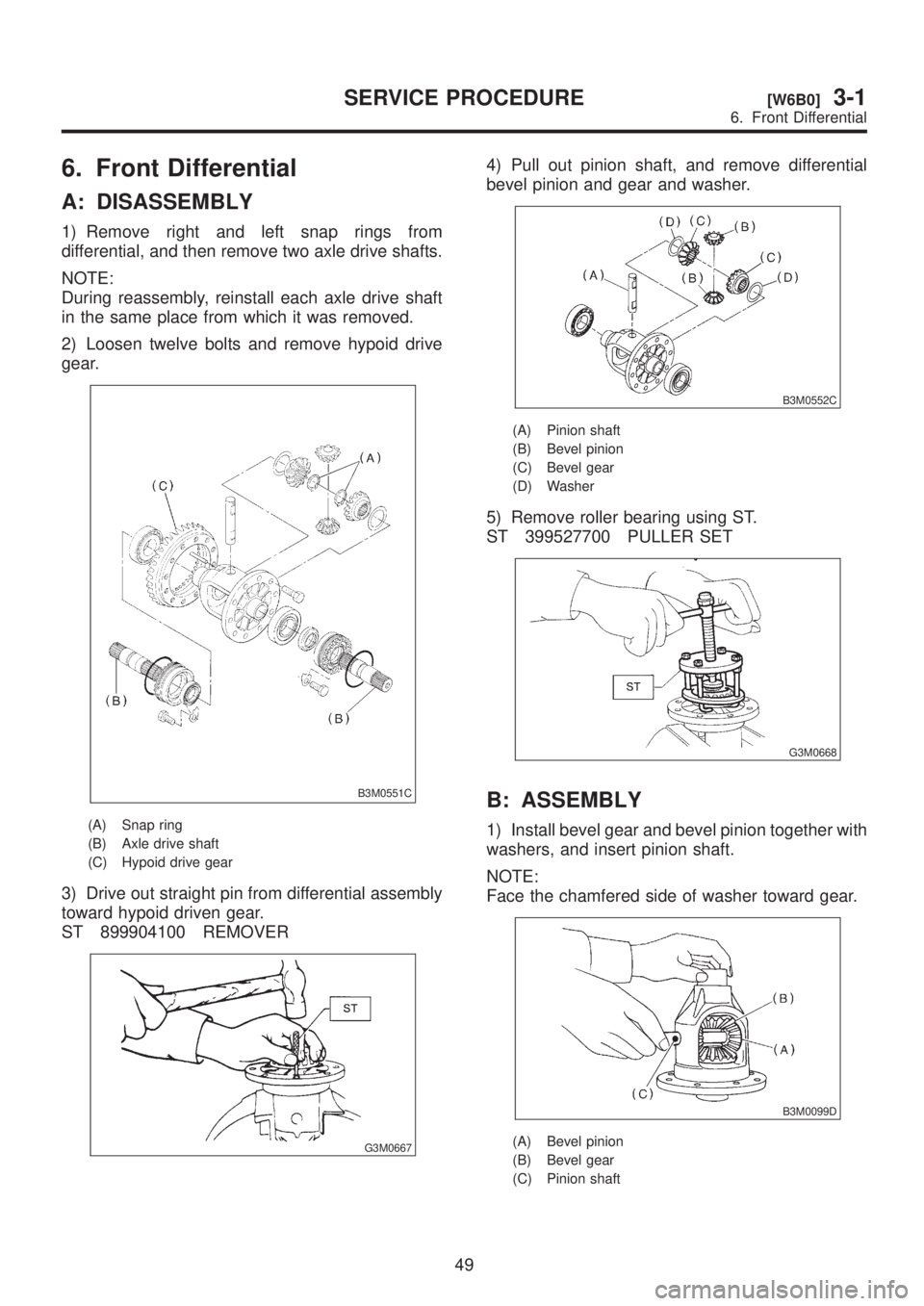
1) Remove right and left snap rings from
differential, and then remove two axle drive shafts.
NOTE:
During reassembly, reinstall each axle drive shaft
in the same place from which it was removed.
2) Loosen twelve bolts and remove hypoid drive
gear.
B3M0551C
(A) Snap ring
(B) Axle drive shaft
(C) Hypoid drive gear
3) Drive out straight pin from differential assembly
toward hypoid driven gear.
ST 899904100 REMOVER
G3M0667
4) Pull out pinion shaft, and remove differential
bevel pinion and gear and washer.
B3M0552C
(A) Pinion shaft
(B) Bevel pinion
(C) Bevel gear
(D) Washer
5) Remove roller bearing using ST.
ST 399527700 PULLER SET
G3M0668
B: ASSEMBLY
1) Install bevel gear and bevel pinion together with
washers, and insert pinion shaft.
NOTE:
Face the chamfered side of washer toward gear.
B3M0099D
(A) Bevel pinion
(B) Bevel gear
(C) Pinion shaft
49
[W6B0]3-1SERVICE PROCEDURE
6. Front Differential
Page 521 of 1456
2) Measure backlash between bevel gear and pin-
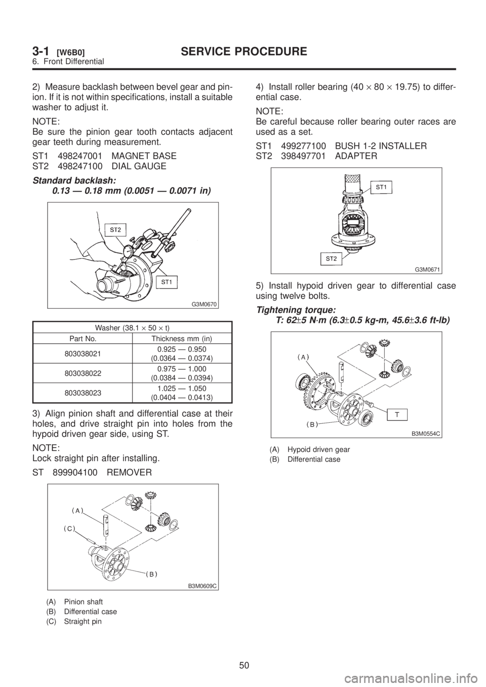
ion. If it is not within specifications, install a suitable
washer to adjust it.
NOTE:
Be sure the pinion gear tooth contacts adjacent
gear teeth during measurement.
ST1 498247001 MAGNET BASE
ST2 498247100 DIAL GAUGE
Standard backlash:
0.13 Ð 0.18 mm (0.0051 Ð 0.0071 in)
G3M0670
Washer (38.1´50´t)
Part No. Thickness mm (in)
8030380210.925 Ð 0.950
(0.0364 Ð 0.0374)
8030380220.975 Ð 1.000
(0.0384 Ð 0.0394)
8030380231.025 Ð 1.050
(0.0404 Ð 0.0413)
3) Align pinion shaft and differential case at their
holes, and drive straight pin into holes from the
hypoid driven gear side, using ST.
NOTE:
Lock straight pin after installing.
ST 899904100 REMOVER
B3M0609C
(A) Pinion shaft
(B) Differential case
(C) Straight pin
4) Install roller bearing (40´80´19.75) to differ-
ential case.
NOTE:
Be careful because roller bearing outer races are
used as a set.
ST1 499277100 BUSH 1-2 INSTALLER
ST2 398497701 ADAPTER
G3M0671
5) Install hypoid driven gear to differential case
using twelve bolts.
Tightening torque:
T: 6 2
±5 N´m (6.3±0.5 kg-m, 45.6±3.6 ft-lb)
B3M0554C
(A) Hypoid driven gear
(B) Differential case
50
3-1[W6B0]SERVICE PROCEDURE
6. Front Differential
Page 522 of 1456
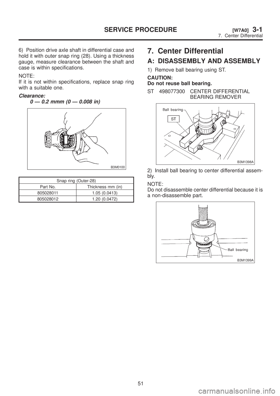
6) Position drive axle shaft in differential case and
hold it with outer snap ring (28). Using a thickness
gauge, measure clearance between the shaft and
case is within specifications.
NOTE:
If it is not within specifications, replace snap ring
with a suitable one.
Clearance:
0 Ð 0.2 mmm (0 Ð 0.008 in)
B3M0100
Snap ring (Outer-28)
Part No. Thickness mm (in)
805028011 1.05 (0.0413)
805028012 1.20 (0.0472)
7. Center Differential
A: DISASSEMBLY AND ASSEMBLY
1) Remove ball bearing using ST.
CAUTION:
Do not reuse ball bearing.
ST 498077300 CENTER DIFFERENTIAL
BEARING REMOVER
B3M1398A
2) Install ball bearing to center differential assem-
bly.
NOTE:
Do not disassemble center differential because it is
a non-disassemble part.
B3M1399A
51
[W7A0]3-1SERVICE PROCEDURE
7. Center Differential
Page 523 of 1456
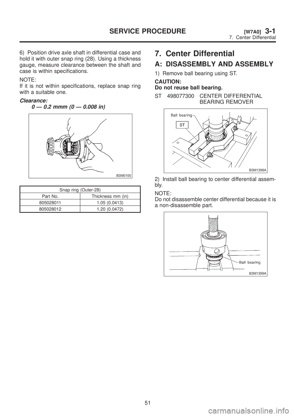
6) Position drive axle shaft in differential case and
hold it with outer snap ring (28). Using a thickness
gauge, measure clearance between the shaft and
case is within specifications.
NOTE:
If it is not within specifications, replace snap ring
with a suitable one.
Clearance:
0 Ð 0.2 mmm (0 Ð 0.008 in)
B3M0100
Snap ring (Outer-28)
Part No. Thickness mm (in)
805028011 1.05 (0.0413)
805028012 1.20 (0.0472)
7. Center Differential
A: DISASSEMBLY AND ASSEMBLY
1) Remove ball bearing using ST.
CAUTION:
Do not reuse ball bearing.
ST 498077300 CENTER DIFFERENTIAL
BEARING REMOVER
B3M1398A
2) Install ball bearing to center differential assem-
bly.
NOTE:
Do not disassemble center differential because it is
a non-disassemble part.
B3M1399A
51
[W7A0]3-1SERVICE PROCEDURE
7. Center Differential
Page 525 of 1456
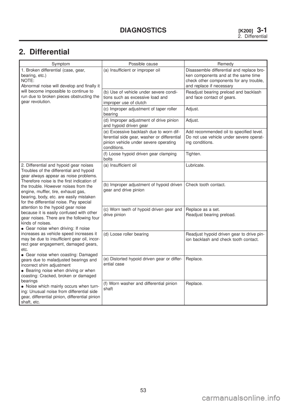
2. Differential
Symptom Possible cause Remedy
1. Broken differential (case, gear,
bearing, etc.)
NOTE:
Abnormal noise will develop and finally it
will become impossible to continue to
run due to broken pieces obstructing the
gear revolution.(a) Insufficient or improper oil Disassemble differential and replace bro-
ken components and at the same time
check other components for any trouble,
and replace if necessary
(b) Use of vehicle under severe condi-
tions such as excessive load and
improper use of clutchReadjust bearing preload and backlash
and face contact of gears.
(c) Improper adjustment of taper roller
bearingAdjust.
(d) Improper adjustment of drive pinion
and hypoid driven gearAdjust.
(e) Excessive backlash due to worn dif-
ferential side gear, washer or differential
pinion vehicle under severe operating
conditions.Add recommended oil to specified level.
Do not use vehicle under severe operat-
ing conditions.
(f) Loose hypoid driven gear clamping
boltsTighten.
2. Differential and hypoid gear noises
Troubles of the differential and hypoid
gear always appear as noise problems.
Therefore noise is the first indication of
the trouble. However noises from the
engine, muffler, tire, exhaust gas,
bearing, body, etc. are easily mistaken
for the differential noise. Pay special
attention to the hypoid gear noise
because it is easily confused with other
gear noises. There are the following four
kinds of noises.
IGear noise when driving: If noise
increases as vehicle speed increases it
may be due to insufficient gear oil, incor-
rect gear engagement, damaged gears,
etc.
IGear noise when coasting: Damaged
gears due to maladjusted bearings and
incorrect shim adjustment
IBearing noise when driving or when
coasting: Cracked, broken or damaged
bearings
INoise which mainly occurs when turn-
ing: Unusual noise from differential side
gear, differential pinion, differential pinion
shaft, etc.(a) Insufficient oil Lubricate.
(b) Improper adjustment of hypoid driven
gear and drive pinionCheck tooth contact.
(c) Worn teeth of hypoid driven gear and
drive pinionReplace as a set.
Readjust bearing preload.
(d) Loose roller bearing Readjust hypoid driven gear to drive pin-
ion backlash and check tooth contact.
(e) Distorted hypoid driven gear or differ-
ential caseReplace.
(f) Worn washer and differential pinion
shaftReplace.
53
[K200]3-1DIAGNOSTICS
2. Differential
Page 527 of 1456
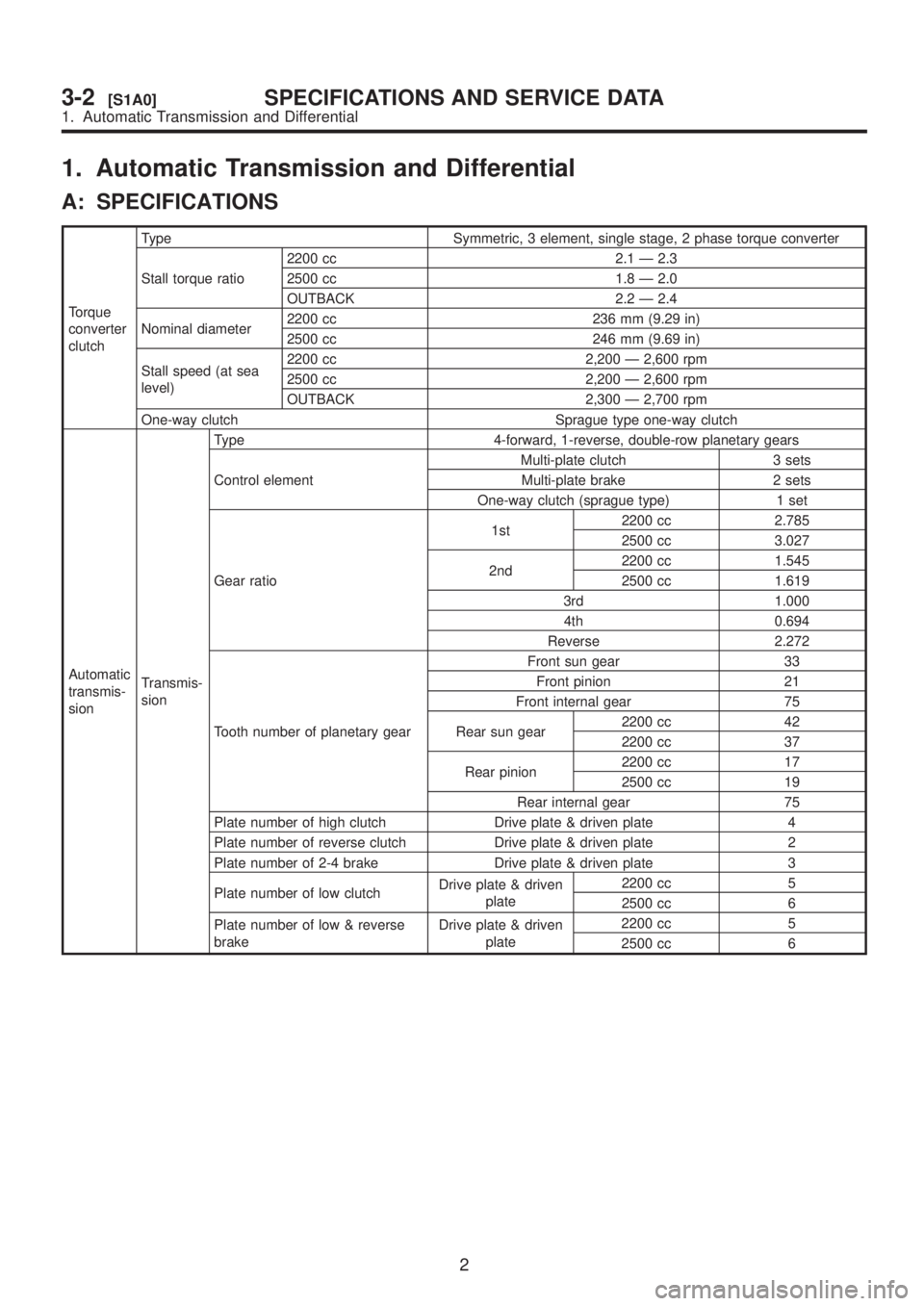
1. Automatic Transmission and Differential
A: SPECIFICATIONS
Torque
converter
clutchType Symmetric, 3 element, single stage, 2 phase torque converter
Stall torque ratio2200 cc 2.1 Ð 2.3
2500 cc 1.8 Ð 2.0
OUTBACK 2.2 Ð 2.4
Nominal diameter2200 cc 236 mm (9.29 in)
2500 cc 246 mm (9.69 in)
Stall speed (at sea
level)2200 cc 2,200 Ð 2,600 rpm
2500 cc 2,200 Ð 2,600 rpm
OUTBACK 2,300 Ð 2,700 rpm
One-way clutch Sprague type one-way clutch
Automatic
transmis-
sionTransmis-
sionType 4-forward, 1-reverse, double-row planetary gears
Control elementMulti-plate clutch 3 sets
Multi-plate brake 2 sets
One-way clutch (sprague type) 1 set
Gear ratio1st2200 cc 2.785
2500 cc 3.027
2nd2200 cc 1.545
2500 cc 1.619
3rd 1.000
4th 0.694
Reverse 2.272
Tooth number of planetary gearFront sun gear 33
Front pinion 21
Front internal gear 75
Rear sun gear2200 cc 42
2200 cc 37
Rear pinion2200 cc 17
2500 cc 19
Rear internal gear 75
Plate number of high clutch Drive plate & driven plate 4
Plate number of reverse clutch Drive plate & driven plate 2
Plate number of 2-4 brake Drive plate & driven plate 3
Plate number of low clutchDrive plate & driven
plate2200 cc 5
2500 cc 6
Plate number of low & reverse
brakeDrive plate & driven
plate2200 cc 5
2500 cc 6
2
3-2[S1A0]SPECIFICATIONS AND SERVICE DATA
1. Automatic Transmission and Differential
Page 528 of 1456
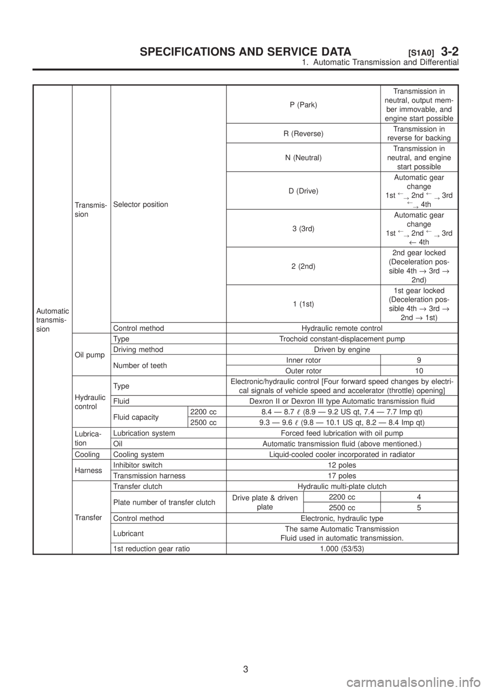
Automatic
transmis-
sionTransmis-
sionSelector positionP (Park)Transmission in
neutral, output mem-
ber immovable, and
engine start possible
R (Reverse)Transmission in
reverse for backing
N (Neutral)Transmission in
neutral, and engine
start possible
D (Drive)Automatic gear
change
1st
¬
®2nd¬
®3rd¬
®4th
3 (3rd)Automatic gear
change
1st
¬
®2nd¬
®3rd
¬4th
2 (2nd)2nd gear locked
(Deceleration pos-
sible 4th®3rd®
2nd)
1 (1st)1st gear locked
(Deceleration pos-
sible 4th®3rd®
2nd®1st)
Control method Hydraulic remote control
Oil pumpType Trochoid constant-displacement pump
Driving method Driven by engine
Number of teethInner rotor 9
Outer rotor 10
Hydraulic
controlTypeElectronic/hydraulic control [Four forward speed changes by electri-
cal signals of vehicle speed and accelerator (throttle) opening]
Fluid Dexron II or Dexron III type Automatic transmission fluid
Fluid capacity2200 cc 8.4 Ð 8.7(8.9 Ð 9.2 US qt, 7.4 Ð 7.7 Imp qt)
2500 cc 9.3 Ð 9.6(9.8 Ð 10.1 US qt, 8.2 Ð 8.4 Imp qt)
Lubrica-
tionLubrication system Forced feed lubrication with oil pump
Oil Automatic transmission fluid (above mentioned.)
Cooling Cooling system Liquid-cooled cooler incorporated in radiator
HarnessInhibitor switch 12 poles
Transmission harness 17 poles
TransferTransfer clutch Hydraulic multi-plate clutch
Plate number of transfer clutchDrive plate & driven
plate2200 cc 4
2500 cc 5
Control method Electronic, hydraulic type
LubricantThe same Automatic Transmission
Fluid used in automatic transmission.
1st reduction gear ratio 1.000 (53/53)
3
[S1A0]3-2SPECIFICATIONS AND SERVICE DATA
1. Automatic Transmission and Differential