high SUBARU LEGACY 1999 Service Owner's Manual
[x] Cancel search | Manufacturer: SUBARU, Model Year: 1999, Model line: LEGACY, Model: SUBARU LEGACY 1999Pages: 1456, PDF Size: 59.93 MB
Page 605 of 1456
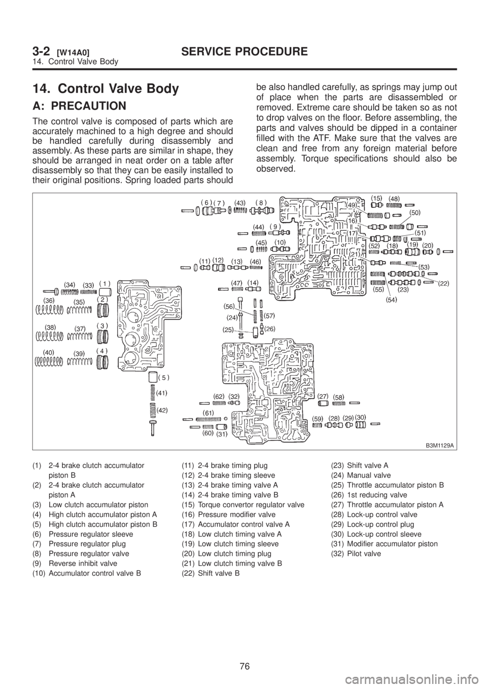
14. Control Valve Body
A: PRECAUTION
The control valve is composed of parts which are
accurately machined to a high degree and should
be handled carefully during disassembly and
assembly. As these parts are similar in shape, they
should be arranged in neat order on a table after
disassembly so that they can be easily installed to
their original positions. Spring loaded parts shouldbe also handled carefully, as springs may jump out
of place when the parts are disassembled or
removed. Extreme care should be taken so as not
to drop valves on the floor. Before assembling, the
parts and valves should be dipped in a container
filled with the ATF. Make sure that the valves are
clean and free from any foreign material before
assembly. Torque specifications should also be
observed.
B3M1129A
(1) 2-4 brake clutch accumulator
piston B
(2) 2-4 brake clutch accumulator
piston A
(3) Low clutch accumulator piston
(4) High clutch accumulator piston A
(5) High clutch accumulator piston B
(6) Pressure regulator sleeve
(7) Pressure regulator plug
(8) Pressure regulator valve
(9) Reverse inhibit valve
(10) Accumulator control valve B(11) 2-4 brake timing plug
(12) 2-4 brake timing sleeve
(13) 2-4 brake timing valve A
(14) 2-4 brake timing valve B
(15) Torque convertor regulator valve
(16) Pressure modifier valve
(17) Accumulator control valve A
(18) Low clutch timing valve A
(19) Low clutch timing sleeve
(20) Low clutch timing plug
(21) Low clutch timing valve B
(22) Shift valve B(23) Shift valve A
(24) Manual valve
(25) Throttle accumulator piston B
(26) 1st reducing valve
(27) Throttle accumulator piston A
(28) Lock-up control valve
(29) Lock-up control plug
(30) Lock-up control sleeve
(31) Modifier accumulator piston
(32) Pilot valve
76
3-2[W14A0]SERVICE PROCEDURE
14. Control Valve Body
Page 606 of 1456
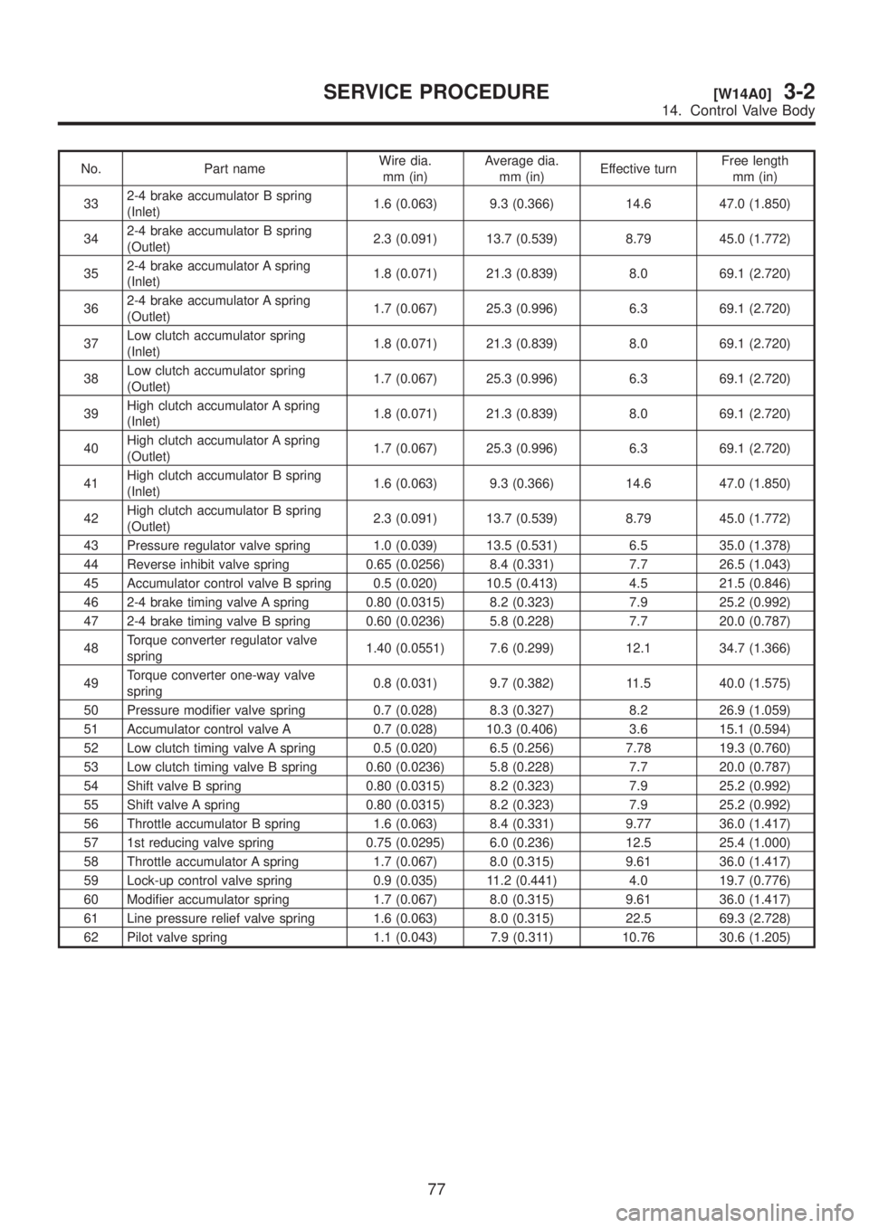
No. Part nameWire dia.
mm (in)Average dia.
mm (in)Effective turnFree length
mm (in)
332-4 brake accumulator B spring
(Inlet)1.6 (0.063) 9.3 (0.366) 14.6 47.0 (1.850)
342-4 brake accumulator B spring
(Outlet)2.3 (0.091) 13.7 (0.539) 8.79 45.0 (1.772)
352-4 brake accumulator A spring
(Inlet)1.8 (0.071) 21.3 (0.839) 8.0 69.1 (2.720)
362-4 brake accumulator A spring
(Outlet)1.7 (0.067) 25.3 (0.996) 6.3 69.1 (2.720)
37Low clutch accumulator spring
(Inlet)1.8 (0.071) 21.3 (0.839) 8.0 69.1 (2.720)
38Low clutch accumulator spring
(Outlet)1.7 (0.067) 25.3 (0.996) 6.3 69.1 (2.720)
39High clutch accumulator A spring
(Inlet)1.8 (0.071) 21.3 (0.839) 8.0 69.1 (2.720)
40High clutch accumulator A spring
(Outlet)1.7 (0.067) 25.3 (0.996) 6.3 69.1 (2.720)
41High clutch accumulator B spring
(Inlet)1.6 (0.063) 9.3 (0.366) 14.6 47.0 (1.850)
42High clutch accumulator B spring
(Outlet)2.3 (0.091) 13.7 (0.539) 8.79 45.0 (1.772)
43 Pressure regulator valve spring 1.0 (0.039) 13.5 (0.531) 6.5 35.0 (1.378)
44 Reverse inhibit valve spring 0.65 (0.0256) 8.4 (0.331) 7.7 26.5 (1.043)
45 Accumulator control valve B spring 0.5 (0.020) 10.5 (0.413) 4.5 21.5 (0.846)
46 2-4 brake timing valve A spring 0.80 (0.0315) 8.2 (0.323) 7.9 25.2 (0.992)
47 2-4 brake timing valve B spring 0.60 (0.0236) 5.8 (0.228) 7.7 20.0 (0.787)
48Torque converter regulator valve
spring1.40 (0.0551) 7.6 (0.299) 12.1 34.7 (1.366)
49Torque converter one-way valve
spring0.8 (0.031) 9.7 (0.382) 11.5 40.0 (1.575)
50 Pressure modifier valve spring 0.7 (0.028) 8.3 (0.327) 8.2 26.9 (1.059)
51 Accumulator control valve A 0.7 (0.028) 10.3 (0.406) 3.6 15.1 (0.594)
52 Low clutch timing valve A spring 0.5 (0.020) 6.5 (0.256) 7.78 19.3 (0.760)
53 Low clutch timing valve B spring 0.60 (0.0236) 5.8 (0.228) 7.7 20.0 (0.787)
54 Shift valve B spring 0.80 (0.0315) 8.2 (0.323) 7.9 25.2 (0.992)
55 Shift valve A spring 0.80 (0.0315) 8.2 (0.323) 7.9 25.2 (0.992)
56 Throttle accumulator B spring 1.6 (0.063) 8.4 (0.331) 9.77 36.0 (1.417)
57 1st reducing valve spring 0.75 (0.0295) 6.0 (0.236) 12.5 25.4 (1.000)
58 Throttle accumulator A spring 1.7 (0.067) 8.0 (0.315) 9.61 36.0 (1.417)
59 Lock-up control valve spring 0.9 (0.035) 11.2 (0.441) 4.0 19.7 (0.776)
60 Modifier accumulator spring 1.7 (0.067) 8.0 (0.315) 9.61 36.0 (1.417)
61 Line pressure relief valve spring 1.6 (0.063) 8.0 (0.315) 22.5 69.3 (2.728)
62 Pilot valve spring 1.1 (0.043) 7.9 (0.311) 10.76 30.6 (1.205)
77
[W14A0]3-2SERVICE PROCEDURE
14. Control Valve Body
Page 616 of 1456
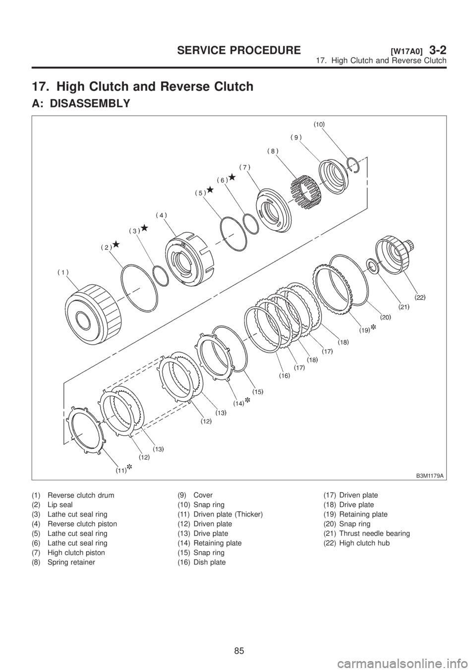
17. High Clutch and Reverse Clutch
A: DISASSEMBLY
B3M1179A
(1) Reverse clutch drum
(2) Lip seal
(3) Lathe cut seal ring
(4) Reverse clutch piston
(5) Lathe cut seal ring
(6) Lathe cut seal ring
(7) High clutch piston
(8) Spring retainer(9) Cover
(10) Snap ring
(11) Driven plate (Thicker)
(12) Driven plate
(13) Drive plate
(14) Retaining plate
(15) Snap ring
(16) Dish plate(17) Driven plate
(18) Drive plate
(19) Retaining plate
(20) Snap ring
(21) Thrust needle bearing
(22) High clutch hub
85
[W17A0]3-2SERVICE PROCEDURE
17. High Clutch and Reverse Clutch
Page 617 of 1456
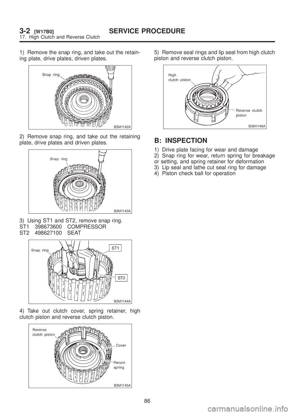
1) Remove the snap ring, and take out the retain-
ing plate, drive plates, driven plates.
B3M1142A
2) Remove snap ring, and take out the retaining
plate, drive plates and driven plates.
B3M1143A
3) Using ST1 and ST2, remove snap ring.
ST1 398673600 COMPRESSOR
ST2 498627100 SEAT
B3M1144A
4) Take out clutch cover, spring retainer, high
clutch piston and reverse clutch piston.
B3M1145A
5) Remove seal rings and lip seal from high clutch
piston and reverse clutch piston.
B3M1146A
B: INSPECTION
1) Drive plate facing for wear and damage
2) Snap ring for wear, return spring for breakage
or setting, and spring retainer for deformation
3) Lip seal and lathe cut seal ring for damage
4) Piston check ball for operation
86
3-2[W17B0]SERVICE PROCEDURE
17. High Clutch and Reverse Clutch
Page 618 of 1456
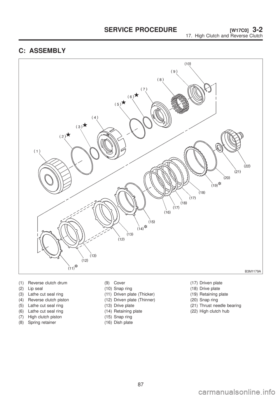
C: ASSEMBLY
B3M1179A
(1) Reverse clutch drum
(2) Lip seal
(3) Lathe cut seal ring
(4) Reverse clutch piston
(5) Lathe cut seal ring
(6) Lathe cut seal ring
(7) High clutch piston
(8) Spring retainer(9) Cover
(10) Snap ring
(11) Driven plate (Thicker)
(12) Driven plate (Thinner)
(13) Drive plate
(14) Retaining plate
(15) Snap ring
(16) Dish plate(17) Driven plate
(18) Drive plate
(19) Retaining plate
(20) Snap ring
(21) Thrust needle bearing
(22) High clutch hub
87
[W17C0]3-2SERVICE PROCEDURE
17. High Clutch and Reverse Clutch
Page 619 of 1456
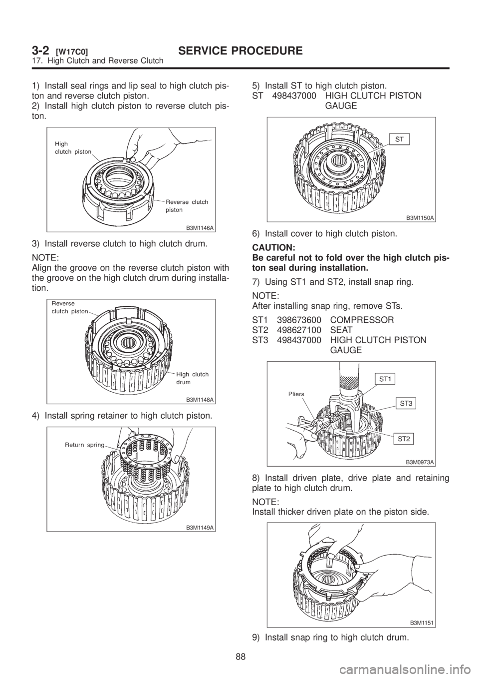
1) Install seal rings and lip seal to high clutch pis-
ton and reverse clutch piston.
2) Install high clutch piston to reverse clutch pis-
ton.
B3M1146A
3) Install reverse clutch to high clutch drum.
NOTE:
Align the groove on the reverse clutch piston with
the groove on the high clutch drum during installa-
tion.
B3M1148A
4) Install spring retainer to high clutch piston.
B3M1149A
5) Install ST to high clutch piston.
ST 498437000 HIGH CLUTCH PISTON
GAUGE
B3M1150A
6) Install cover to high clutch piston.
CAUTION:
Be careful not to fold over the high clutch pis-
ton seal during installation.
7) Using ST1 and ST2, install snap ring.
NOTE:
After installing snap ring, remove STs.
ST1 398673600 COMPRESSOR
ST2 498627100 SEAT
ST3 498437000 HIGH CLUTCH PISTON
GAUGE
B3M0973A
8) Install driven plate, drive plate and retaining
plate to high clutch drum.
NOTE:
Install thicker driven plate on the piston side.
B3M1151
9) Install snap ring to high clutch drum.
88
3-2[W17C0]SERVICE PROCEDURE
17. High Clutch and Reverse Clutch
Page 620 of 1456
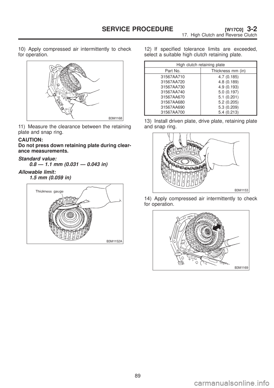
10) Apply compressed air intermittently to check
for operation.
B3M1168
11) Measure the clearance between the retaining
plate and snap ring.
CAUTION:
Do not press down retaining plate during clear-
ance measurements.
Standard value:
0.8 Ð 1.1 mm (0.031 Ð 0.043 in)
Allowable limit:
1.5 mm (0.059 in)
B3M1152A
12) If specified tolerance limits are exceeded,
select a suitable high clutch retaining plate.
High clutch retaining plate
Part No. Thickness mm (in)
31567AA710
31567AA720
31567AA730
31567AA740
31567AA670
31567AA680
31567AA690
31567AA7004.7 (0.185)
4.8 (0.189)
4.9 (0.193)
5.0 (0.197)
5.1 (0.201)
5.2 (0.205)
5.3 (0.209)
5.4 (0.213)
13) Install driven plate, drive plate, retaining plate
and snap ring.
B3M1153
14) Apply compressed air intermittently to check
for operation.
B3M1169
89
[W17C0]3-2SERVICE PROCEDURE
17. High Clutch and Reverse Clutch
Page 621 of 1456
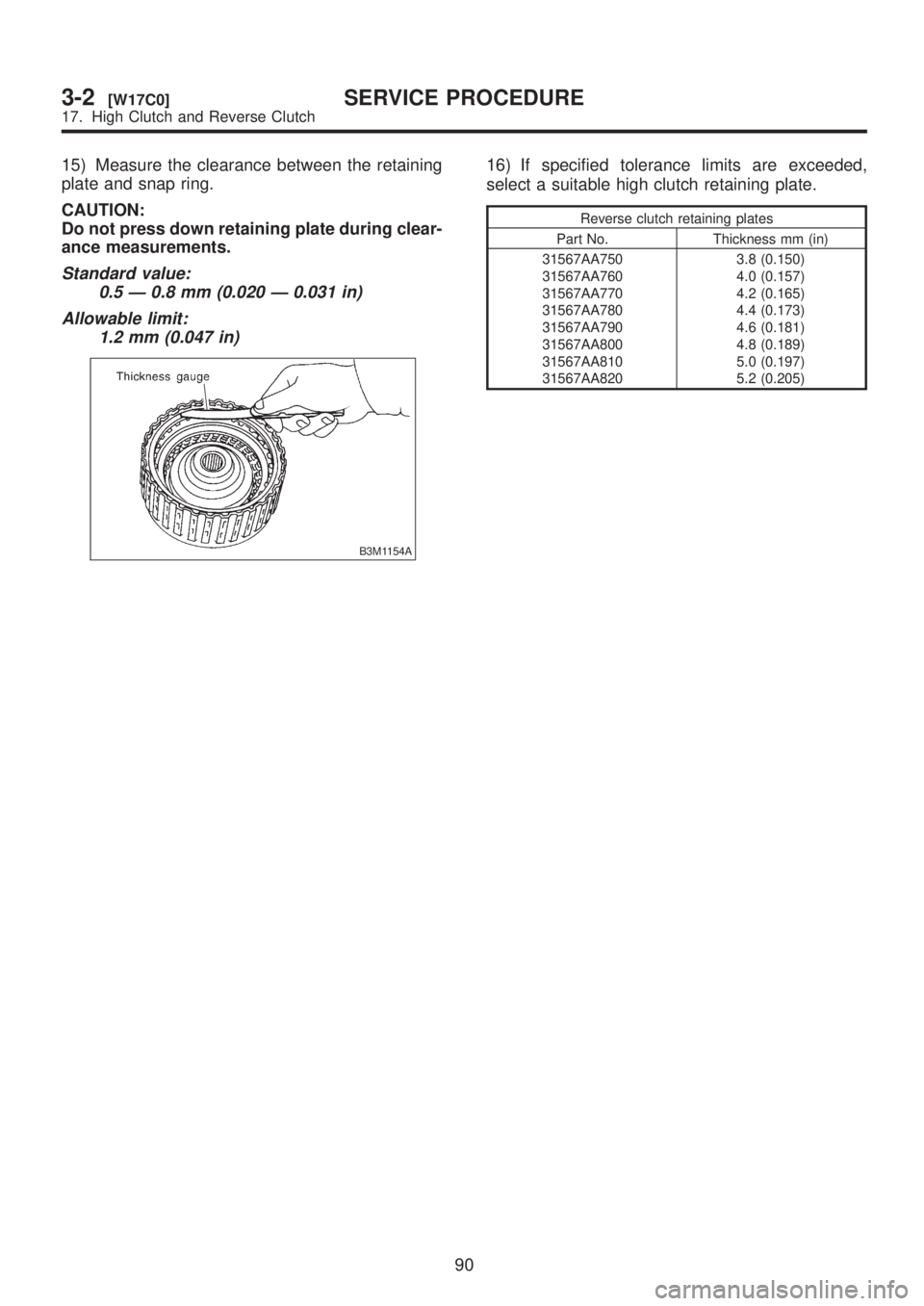
15) Measure the clearance between the retaining
plate and snap ring.
CAUTION:
Do not press down retaining plate during clear-
ance measurements.
Standard value:
0.5 Ð 0.8 mm (0.020 Ð 0.031 in)
Allowable limit:
1.2 mm (0.047 in)
B3M1154A
16) If specified tolerance limits are exceeded,
select a suitable high clutch retaining plate.
Reverse clutch retaining plates
Part No. Thickness mm (in)
31567AA750
31567AA760
31567AA770
31567AA780
31567AA790
31567AA800
31567AA810
31567AA8203.8 (0.150)
4.0 (0.157)
4.2 (0.165)
4.4 (0.173)
4.6 (0.181)
4.8 (0.189)
5.0 (0.197)
5.2 (0.205)
90
3-2[W17C0]SERVICE PROCEDURE
17. High Clutch and Reverse Clutch
Page 811 of 1456
G4M0113
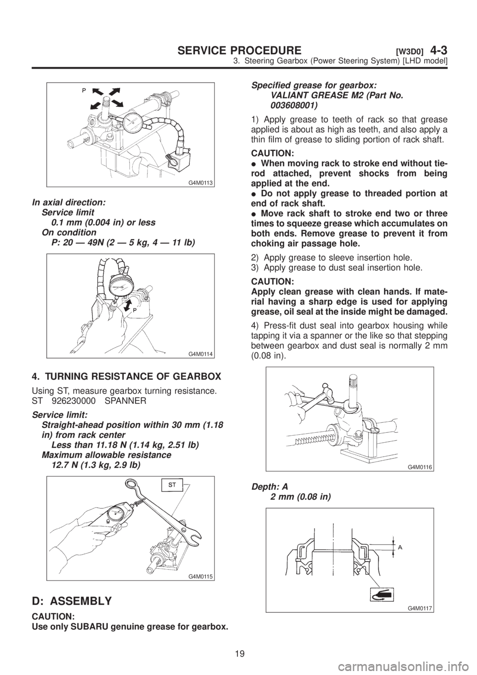
In axial direction:
Service limit
0.1 mm (0.004 in) or less
On condition
P:20Ð49N(2Ð5kg,4Ð11lb)
G4M0114
4. TURNING RESISTANCE OF GEARBOX
Using ST, measure gearbox turning resistance.
ST 926230000 SPANNER
Service limit:
Straight-ahead position within 30 mm (1.18
in) from rack center
Less than 11.18 N (1.14 kg, 2.51 lb)
Maximum allowable resistance
12.7 N (1.3 kg, 2.9 lb)
G4M0115
D: ASSEMBLY
CAUTION:
Use only SUBARU genuine grease for gearbox.
Specified grease for gearbox:
VALIANT GREASE M2 (Part No.
003608001)
1) Apply grease to teeth of rack so that grease
applied is about as high as teeth, and also apply a
thin film of grease to sliding portion of rack shaft.
CAUTION:
IWhen moving rack to stroke end without tie-
rod attached, prevent shocks from being
applied at the end.
IDo not apply grease to threaded portion at
end of rack shaft.
IMove rack shaft to stroke end two or three
times to squeeze grease which accumulates on
both ends. Remove grease to prevent it from
choking air passage hole.
2) Apply grease to sleeve insertion hole.
3) Apply grease to dust seal insertion hole.
CAUTION:
Apply clean grease with clean hands. If mate-
rial having a sharp edge is used for applying
grease, oil seal at the inside might be damaged.
4) Press-fit dust seal into gearbox housing while
tapping it via a spanner or the like so that stepping
between gearbox and dust seal is normally 2 mm
(0.08 in).
G4M0116
Depth: A
2 mm (0.08 in)
G4M0117
19
[W3D0]4-3SERVICE PROCEDURE
3. Steering Gearbox (Power Steering System) [LHD model]
Page 854 of 1456
G4M0172
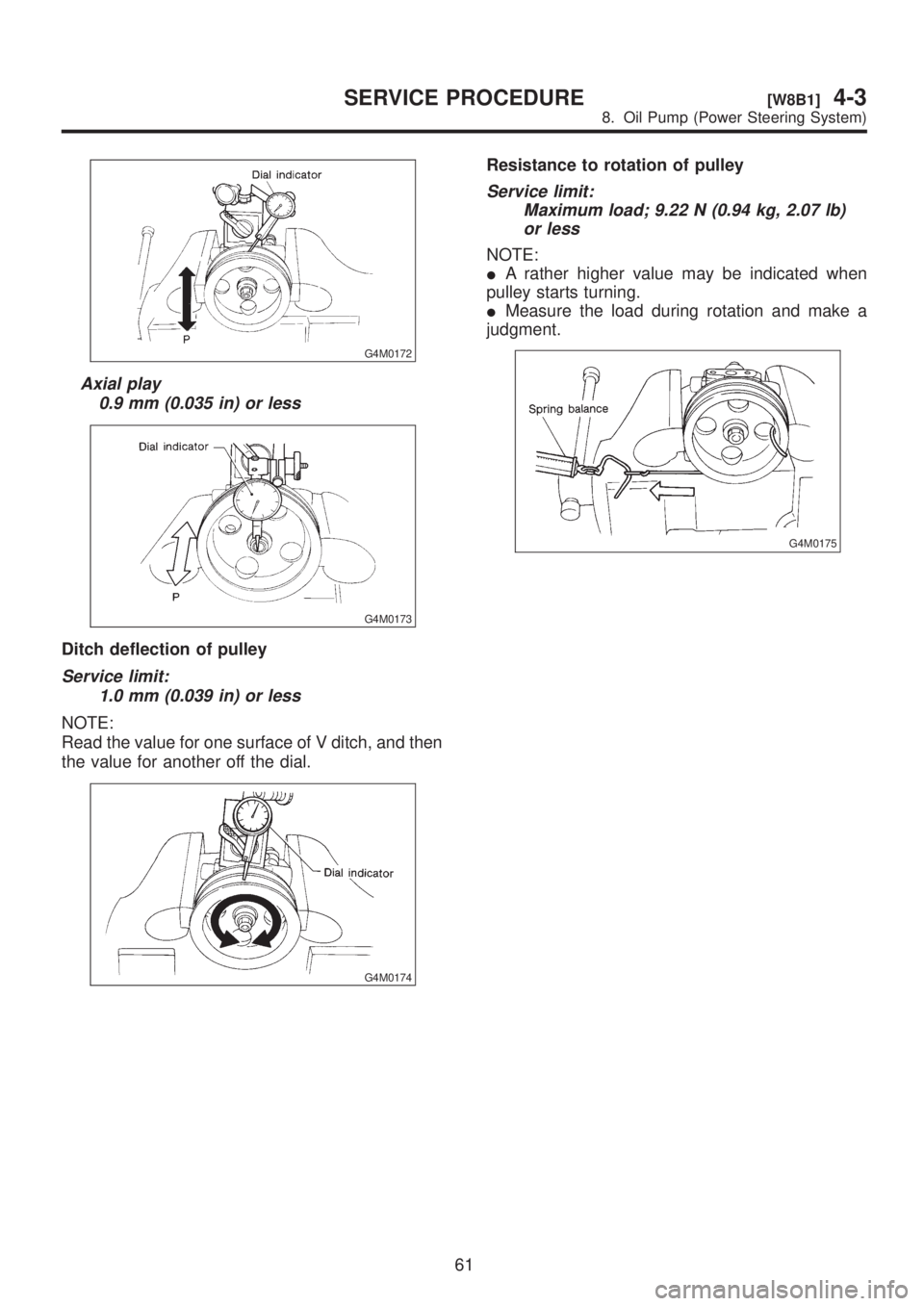
Axial play
0.9 mm (0.035 in) or less
G4M0173
Ditch deflection of pulley
Service limit:
1.0 mm (0.039 in) or less
NOTE:
Read the value for one surface of V ditch, and then
the value for another off the dial.
G4M0174
Resistance to rotation of pulley
Service limit:
Maximum load; 9.22 N (0.94 kg, 2.07 lb)
or less
NOTE:
IA rather higher value may be indicated when
pulley starts turning.
IMeasure the load during rotation and make a
judgment.
G4M0175
61
[W8B1]4-3SERVICE PROCEDURE
8. Oil Pump (Power Steering System)