high SUBARU LEGACY 1999 Service Manual PDF
[x] Cancel search | Manufacturer: SUBARU, Model Year: 1999, Model line: LEGACY, Model: SUBARU LEGACY 1999Pages: 1456, PDF Size: 59.93 MB
Page 1135 of 1456
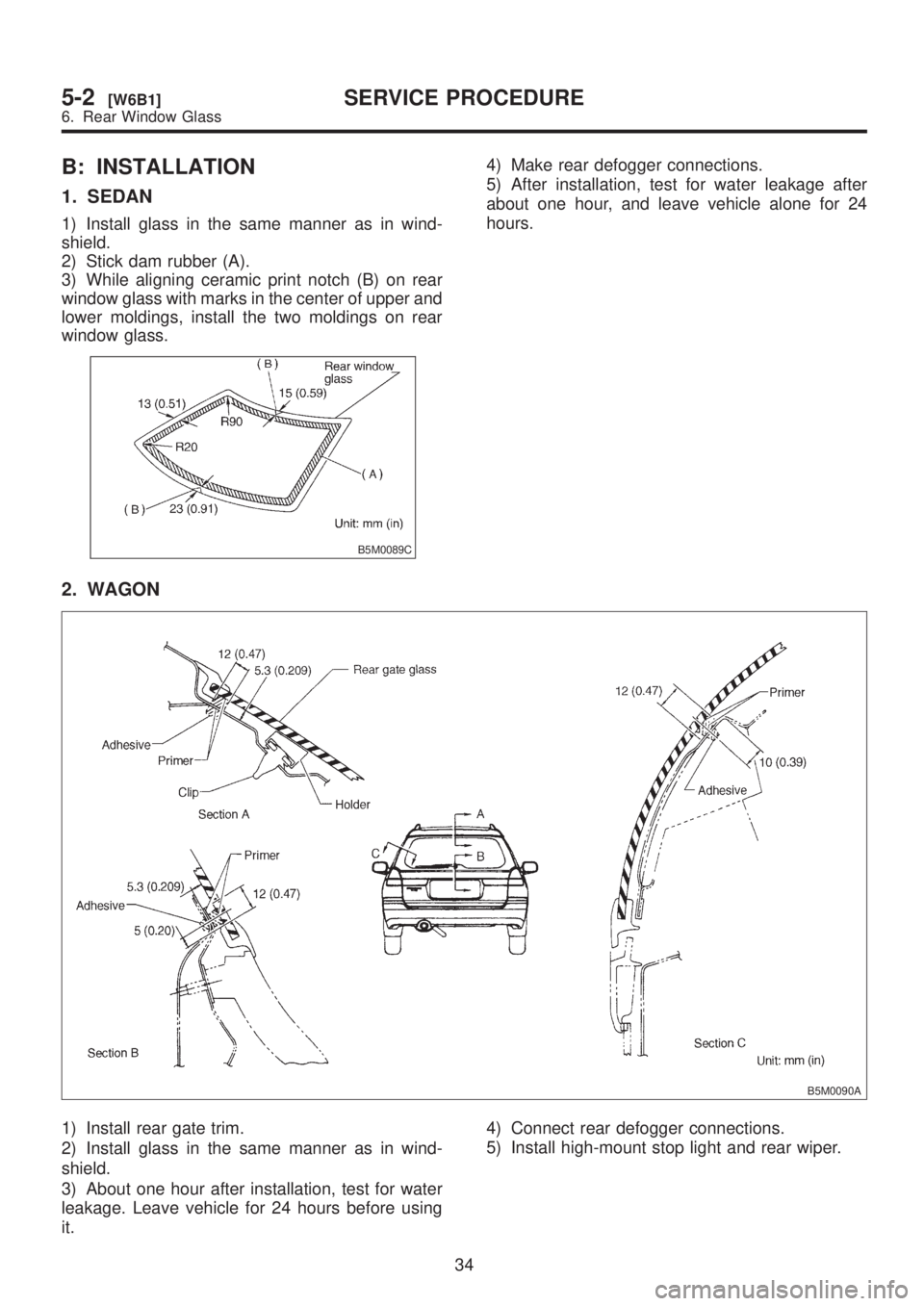
B: INSTALLATION
1. SEDAN
1) Install glass in the same manner as in wind-
shield.
2) Stick dam rubber (A).
3) While aligning ceramic print notch (B) on rear
window glass with marks in the center of upper and
lower moldings, install the two moldings on rear
window glass.
B5M0089C
4) Make rear defogger connections.
5) After installation, test for water leakage after
about one hour, and leave vehicle alone for 24
hours.
2. WAGON
B5M0090A
1) Install rear gate trim.
2) Install glass in the same manner as in wind-
shield.
3) About one hour after installation, test for water
leakage. Leave vehicle for 24 hours before using
it.4) Connect rear defogger connections.
5) Install high-mount stop light and rear wiper.
34
5-2[W6B1]SERVICE PROCEDURE
6. Rear Window Glass
Page 1138 of 1456
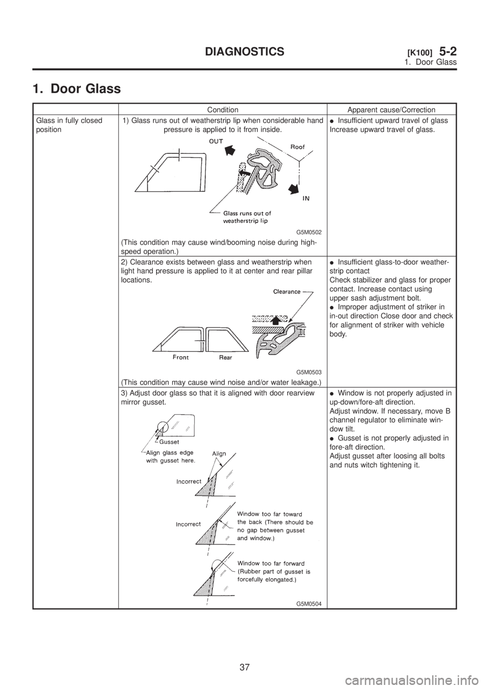
1. Door Glass
Condition Apparent cause/Correction
Glass in fully closed
position1) Glass runs out of weatherstrip lip when considerable hand
pressure is applied to it from inside.
G5M0502
IInsufficient upward travel of glass
Increase upward travel of glass.
(This condition may cause wind/booming noise during high-
speed operation.)
2) Clearance exists between glass and weatherstrip when
light hand pressure is applied to it at center and rear pillar
locations.
G5M0503
IInsufficient glass-to-door weather-
strip contact
Check stabilizer and glass for proper
contact. Increase contact using
upper sash adjustment bolt.
IImproper adjustment of striker in
in-out direction Close door and check
for alignment of striker with vehicle
body.
(This condition may cause wind noise and/or water leakage.)
3) Adjust door glass so that it is aligned with door rearview
mirror gusset.
G5M0504
IWindow is not properly adjusted in
up-down/fore-aft direction.
Adjust window. If necessary, move B
channel regulator to eliminate win-
dow tilt.
IGusset is not properly adjusted in
fore-aft direction.
Adjust gusset after loosing all bolts
and nuts witch tightening it.
37
[K100]5-2DIAGNOSTICS
1. Door Glass
Page 1139 of 1456
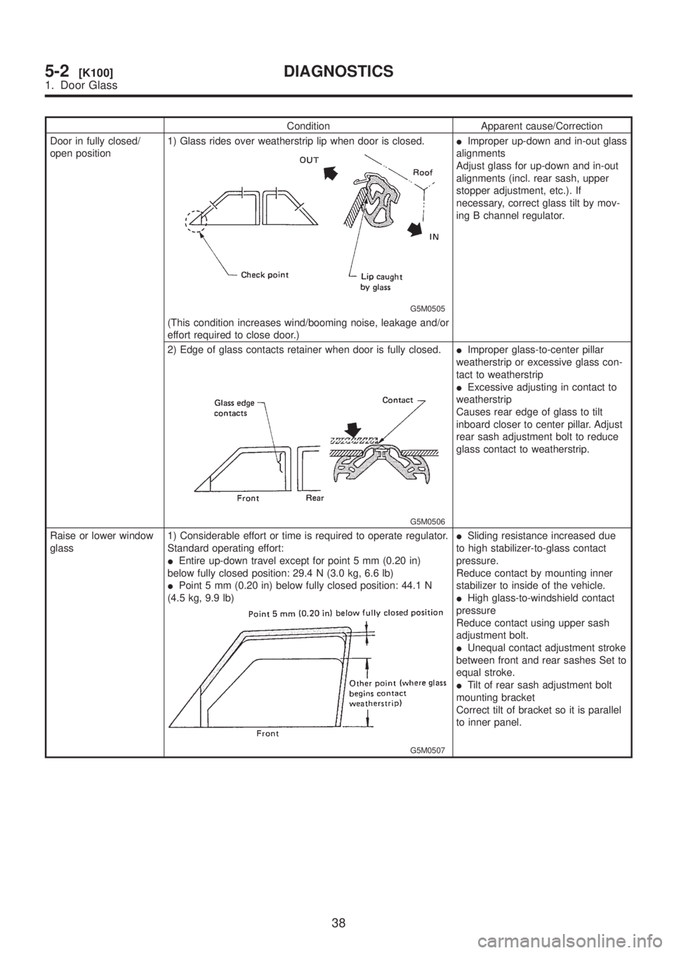
Condition Apparent cause/Correction
Door in fully closed/
open position1) Glass rides over weatherstrip lip when door is closed.
G5M0505
IImproper up-down and in-out glass
alignments
Adjust glass for up-down and in-out
alignments (incl. rear sash, upper
stopper adjustment, etc.). If
necessary, correct glass tilt by mov-
ing B channel regulator.
(This condition increases wind/booming noise, leakage and/or
effort required to close door.)
2) Edge of glass contacts retainer when door is fully closed.
G5M0506
IImproper glass-to-center pillar
weatherstrip or excessive glass con-
tact to weatherstrip
IExcessive adjusting in contact to
weatherstrip
Causes rear edge of glass to tilt
inboard closer to center pillar. Adjust
rear sash adjustment bolt to reduce
glass contact to weatherstrip.
Raise or lower window
glass1) Considerable effort or time is required to operate regulator.
Standard operating effort:
IEntire up-down travel except for point 5 mm (0.20 in)
below fully closed position: 29.4 N (3.0 kg, 6.6 lb)
IPoint 5 mm (0.20 in) below fully closed position: 44.1 N
(4.5 kg, 9.9 lb)
G5M0507
ISliding resistance increased due
to high stabilizer-to-glass contact
pressure.
Reduce contact by mounting inner
stabilizer to inside of the vehicle.
IHigh glass-to-windshield contact
pressure
Reduce contact using upper sash
adjustment bolt.
IUnequal contact adjustment stroke
between front and rear sashes Set to
equal stroke.
ITilt of rear sash adjustment bolt
mounting bracket
Correct tilt of bracket so it is parallel
to inner panel.
38
5-2[K100]DIAGNOSTICS
1. Door Glass
Page 1167 of 1456
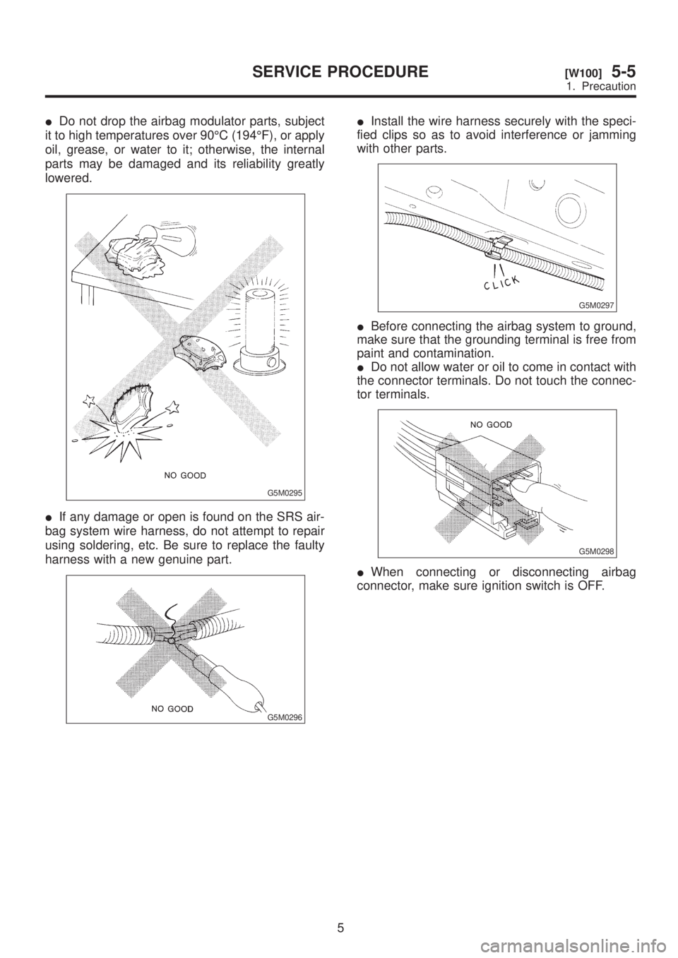
IDo not drop the airbag modulator parts, subject
it to high temperatures over 90ÉC (194ÉF), or apply
oil, grease, or water to it; otherwise, the internal
parts may be damaged and its reliability greatly
lowered.
G5M0295
IIf any damage or open is found on the SRS air-
bag system wire harness, do not attempt to repair
using soldering, etc. Be sure to replace the faulty
harness with a new genuine part.
G5M0296
IInstall the wire harness securely with the speci-
fied clips so as to avoid interference or jamming
with other parts.
G5M0297
IBefore connecting the airbag system to ground,
make sure that the grounding terminal is free from
paint and contamination.
IDo not allow water or oil to come in contact with
the connector terminals. Do not touch the connec-
tor terminals.
G5M0298
IWhen connecting or disconnecting airbag
connector, make sure ignition switch is OFF.
5
[W100]5-5SERVICE PROCEDURE
1. Precaution
Page 1189 of 1456
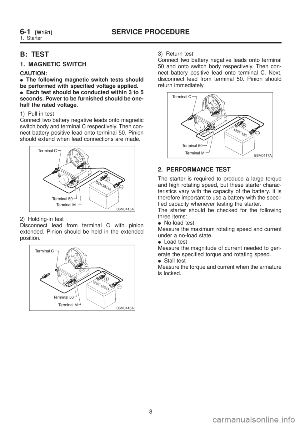
B: TEST
1. MAGNETIC SWITCH
CAUTION:
IThe following magnetic switch tests should
be performed with specified voltage applied.
IEach test should be conducted within 3 to 5
seconds. Power to be furnished should be one-
half the rated voltage.
1) Pull-in test
Connect two battery negative leads onto magnetic
switch body and terminal C respectively. Then con-
nect battery positive lead onto terminal 50. Pinion
should extend when lead connections are made.
B6M0415A
2) Holding-in test
Disconnect lead from terminal C with pinion
extended. Pinion should be held in the extended
position.
B6M0416A
3) Return test
Connect two battery negative leads onto terminal
50 and onto switch body respectively. Then con-
nect battery positive lead onto terminal C. Next,
disconnect lead from terminal 50. Pinion should
return immediately.
B6M0417A
2. PERFORMANCE TEST
The starter is required to produce a large torque
and high rotating speed, but these starter charac-
teristics vary with the capacity of the battery. It is
therefore important to use a battery with the speci-
fied capacity whenever testing the starter.
The starter should be checked for the following
three items:
INo-load test
Measure the maximum rotating speed and current
under a no-load state.
ILoad test
Measure the magnitude of current needed to gen-
erate the specified torque and rotating speed.
IStall test
Measure the torque and current when the armature
is locked.
8
6-1[W1B1]SERVICE PROCEDURE
1. Starter
Page 1190 of 1456
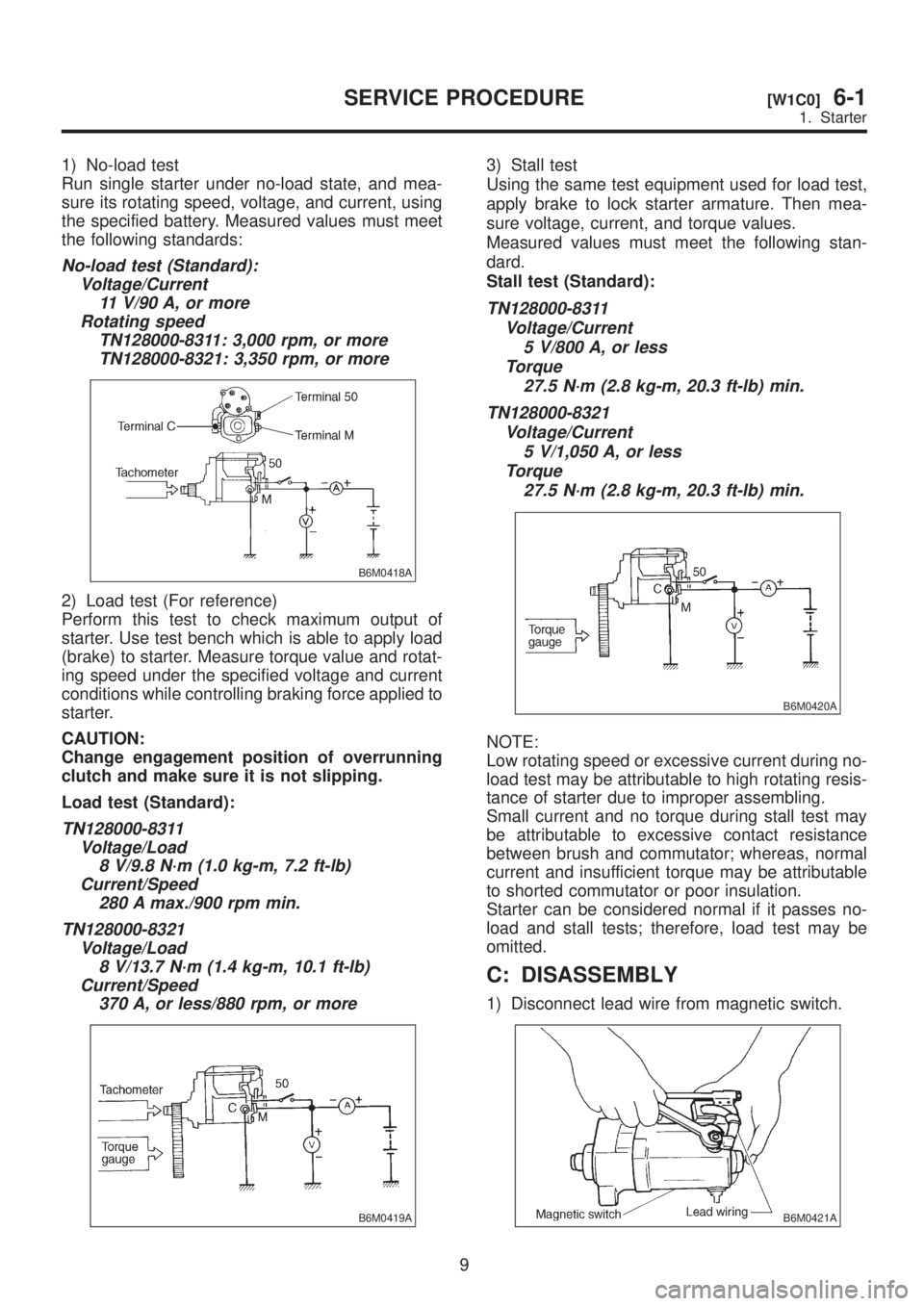
1) No-load test
Run single starter under no-load state, and mea-
sure its rotating speed, voltage, and current, using
the specified battery. Measured values must meet
the following standards:
No-load test (Standard):
Voltage/Current
11 V/90 A, or more
Rotating speed
TN128000-8311: 3,000 rpm, or more
TN128000-8321: 3,350 rpm, or more
B6M0418A
2) Load test (For reference)
Perform this test to check maximum output of
starter. Use test bench which is able to apply load
(brake) to starter. Measure torque value and rotat-
ing speed under the specified voltage and current
conditions while controlling braking force applied to
starter.
CAUTION:
Change engagement position of overrunning
clutch and make sure it is not slipping.
Load test (Standard):
TN128000-8311
Voltage/Load
8 V/9.8 N´m (1.0 kg-m, 7.2 ft-lb)
Current/Speed
280 A max./900 rpm min.
TN128000-8321
Voltage/Load
8 V/13.7 N´m (1.4 kg-m, 10.1 ft-lb)
Current/Speed
370 A, or less/880 rpm, or more
B6M0419A
3) Stall test
Using the same test equipment used for load test,
apply brake to lock starter armature. Then mea-
sure voltage, current, and torque values.
Measured values must meet the following stan-
dard.
Stall test (Standard):
TN128000-8311
Voltage/Current
5 V/800 A, or less
Torque
27.5 N´m (2.8 kg-m, 20.3 ft-lb) min.
TN128000-8321
Voltage/Current
5 V/1,050 A, or less
Torque
27.5 N´m (2.8 kg-m, 20.3 ft-lb) min.
B6M0420A
NOTE:
Low rotating speed or excessive current during no-
load test may be attributable to high rotating resis-
tance of starter due to improper assembling.
Small current and no torque during stall test may
be attributable to excessive contact resistance
between brush and commutator; whereas, normal
current and insufficient torque may be attributable
to shorted commutator or poor insulation.
Starter can be considered normal if it passes no-
load and stall tests; therefore, load test may be
omitted.
C: DISASSEMBLY
1) Disconnect lead wire from magnetic switch.
B6M0421A
9
[W1C0]6-1SERVICE PROCEDURE
1. Starter
Page 1199 of 1456
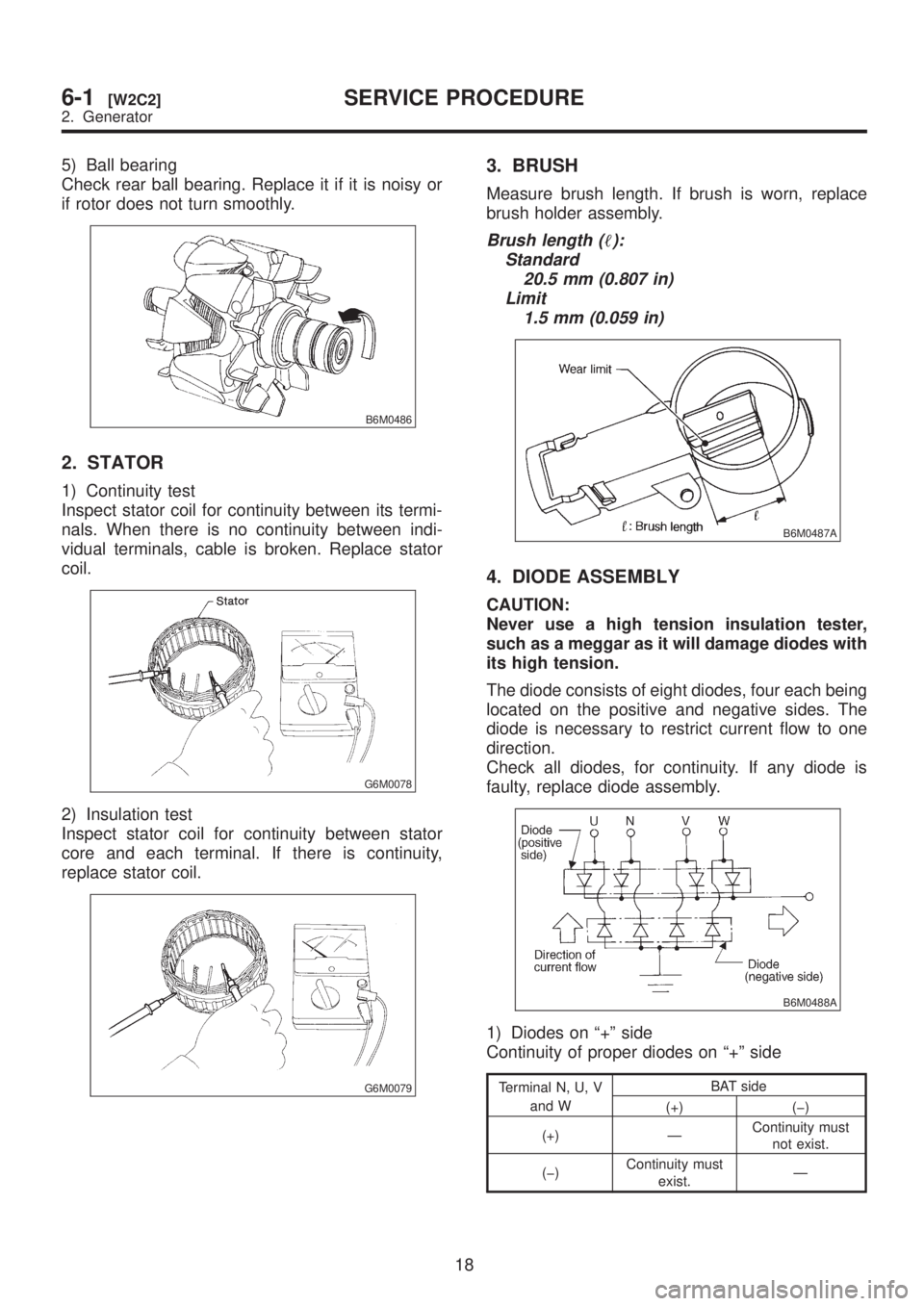
5) Ball bearing
Check rear ball bearing. Replace it if it is noisy or
if rotor does not turn smoothly.
B6M0486
2. STATOR
1) Continuity test
Inspect stator coil for continuity between its termi-
nals. When there is no continuity between indi-
vidual terminals, cable is broken. Replace stator
coil.
G6M0078
2) Insulation test
Inspect stator coil for continuity between stator
core and each terminal. If there is continuity,
replace stator coil.
G6M0079
3. BRUSH
Measure brush length. If brush is worn, replace
brush holder assembly.
Brush length ():
Standard
20.5 mm (0.807 in)
Limit
1.5 mm (0.059 in)
B6M0487A
4. DIODE ASSEMBLY
CAUTION:
Never use a high tension insulation tester,
such as a meggar as it will damage diodes with
its high tension.
The diode consists of eight diodes, four each being
located on the positive and negative sides. The
diode is necessary to restrict current flow to one
direction.
Check all diodes, for continuity. If any diode is
faulty, replace diode assembly.
B6M0488A
1) Diodes on ª+º side
Continuity of proper diodes on ª+º side
Terminal N, U, V
and WBAT side
(+) (þ)
(+) ÐContinuity must
not exist.
(þ)Continuity must
exist.Ð
18
6-1[W2C2]SERVICE PROCEDURE
2. Generator
Page 1223 of 1456
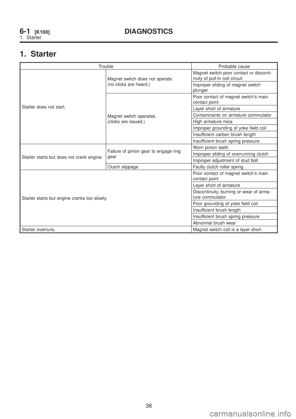
1. Starter
Trouble Probable cause
Starter does not start.Magnet switch does not operate.
(no clicks are heard.)Magnet switch poor contact or disconti-
nuity of pull-in coil circuit
Improper sliding of magnet switch
plunger
Magnet switch operates.
(clicks are issued.)Poor contact of magnet switch's main
contact point
Layer short of armature
Contaminants on armature commutator
High armature mica
Improper grounding of yoke field coil
Insufficient carbon brush length
Insufficient brush spring pressure
Starter starts but does not crank engine.Failure of pinion gear to engage ring
gearWorn pinion teeth
Improper sliding of overrunning clutch
Improper adjustment of stud bolt
Clutch slippage Faulty clutch roller spring
Starter starts but engine cranks too slowly.Poor contact of magnet switch's main
contact point
Layer short of armature
Discontinuity, burning or wear of arma-
ture commutator
Poor grounding of yoke field coil
Insufficient brush length
Insufficient brush spring pressure
Abnormal brush wear
Starter overruns. Magnet switch coil is a layer short.
38
6-1[K100]DIAGNOSTICS
1. Starter
Page 1226 of 1456
1. Body Electrical
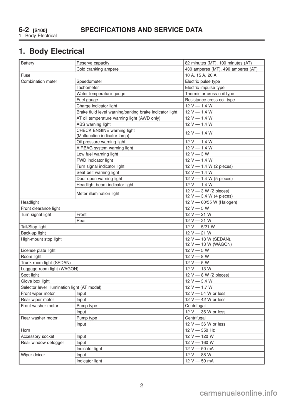
Battery Reserve capacity 82 minutes (MT), 100 minutes (AT)
Cold cranking ampere 430 amperes (MT), 490 amperes (AT)
Fuse10 A, 15 A, 20 A
Combination meter Speedometer Electric pulse type
Tachometer Electric impulse type
Water temperature gauge Thermistor cross coil type
Fuel gauge Resistance cross coil type
Charge indicator light 12 V Ð 1.4 W
Brake fluid level warning/parking brake indicator light 12 V Ð 1.4 W
AT oil temperature warning light (AWD only) 12 V Ð 1.4 W
ABS warning light 12 V Ð 1.4 W
CHECK ENGINE warning light
(Malfunction indicator lamp)12 V Ð 1.4 W
Oil pressure warning light 12 V Ð 1.4 W
AIRBAG system warning light 12 V Ð 1.4 W
Low fuel warning light 12VÐ3W
FWD indicator light 12 V Ð 1.4 W
Turn signal indicator light 12 V Ð 1.4 W (2 pieces)
Seat belt warning light 12 V Ð 1.4 W
Door open warning light 12 V Ð 1.4 W (5 pieces)
Headlight beam indicator light 12 V Ð 1.4 W
Meter illumination light12VÐ3W(2pieces)
12 V Ð 3.4 W (4 pieces)
Headlight12 V Ð 60/55 W (Halogen)
Front clearance light 12VÐ5W
Turn signal light Front 12VÐ21W
Rear 12VÐ21W
Tail/Stop light12 V Ð 5/21 W
Back-up light12VÐ21W
High-mount stop light 12VÐ18W(SEDAN),
12VÐ13W(WAGON)
License plate light 12VÐ5W
Room light12VÐ8W
Trunk room light (SEDAN) 12VÐ5W
Luggage room light (WAGON) 12VÐ13W
Spot light12VÐ8W(2pieces)
Glove box light 12 V Ð 3.4 W
Selector lever illumination light (AT model) 12 V Ð 1.7 W
Front wiper motor Input 12VÐ54Worless
Rear wiper motor Input 12VÐ42Worless
Front washer motor Pump type Centrifugal
Input 12VÐ36Worless
Rear washer motor Pump type Centrifugal
Input 12VÐ36Worless
Horn12 V Ð 350 Hz
Accessory socket Input 12 V Ð 120 W
Rear window defogger Input 12 V Ð 160 W
Indicator light 12VÐ50mA
Wiper deicer Input 12VÐ88W
Indicator light 12VÐ50mA
2
6-2[S100]SPECIFICATIONS AND SERVICE DATA
1. Body Electrical
Page 1231 of 1456
4. Headlight
A: ADJUSTMENT
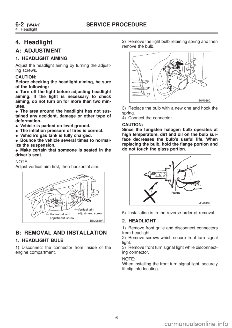
1. HEADLIGHT AIMING
Adjust the headlight aiming by turning the adjust-
ing screws.
CAUTION:
Before checking the headlight aiming, be sure
of the following:
ITurn off the light before adjusting headlight
aiming. If the light is necessary to check
aiming, do not turn on for more than two min-
utes.
IThe area around the headlight has not sus-
tained any accident, damage or other type of
deformation.
IVehicle is parked on level ground.
IThe inflation pressure of tires is correct.
IVehicle's gas tank is fully charged.
IBounce the vehicle several times to normal-
ize the suspension.
IMake certain that someone is seated in the
driver's seat.
NOTE:
Adjust vertical aim first, then horizontal aim.
B6M0859A
B: REMOVAL AND INSTALLATION
1. HEADLIGHT BULB
1) Disconnect the connector from inside of the
engine compartment.2) Remove the light bulb retaining spring and then
remove the bulb.
B6M0860
3) Replace the bulb with a new one and hook the
spring.
4) Connect the connector.
CAUTION:
Since the tungsten halogen bulb operates at
high temperature, dirt and oil on the bulb sur-
face decreases the bulb's useful life. When
replacing the bulb, hold the flange portion and
do not touch the glass portion.
M6A0139
5) Installation is in the reverse order of removal.
2. HEADLIGHT
1) Remove front grille and disconnect connectors
from headlight.
2) Remove screws which secure front turn signal
light.
3) Remove front turn signal light while disconnect-
ing connector.
NOTE:
When installing the front turn signal light, securely
fit clip into locating.
6
6-2[W4A1]SERVICE PROCEDURE
4. Headlight