key SUBARU LEGACY 1999 Service Owner's Manual
[x] Cancel search | Manufacturer: SUBARU, Model Year: 1999, Model line: LEGACY, Model: SUBARU LEGACY 1999Pages: 1456, PDF Size: 59.93 MB
Page 649 of 1456
Also check that ignition key can be removed
only from the ªLOCKº position.
(2) Ensure selector lever moves from ªPº to any
other position when the brake pedal isdepressed with ignition key set at ªONº or
ªSTARTº.
11
[W2E0]3-3SERVICE PROCEDURE
2. Automatic Transmission
Page 804 of 1456
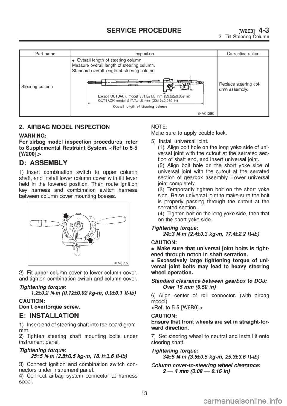
Part name Inspection Corrective action
Steering columnIOverall length of steering column
Measure overall length of steering column.
Standard overall length of steering column:
B4M0129C
Replace steering col-
umn assembly.
2. AIRBAG MODEL INSPECTION
WARNING:
For airbag model inspection procedures, refer
to Supplemental Restraint System.
[W200].>
D: ASSEMBLY
1) Insert combination switch to upper column
shaft, and install lower column cover with tilt lever
held in the lowered position. Then route ignition
key harness and combination switch harness
between column cover mounting bosses.
B4M0555
2) Fit upper column cover to lower column cover,
and tighten combination switch and column cover.
Tightening torque:
1.2
±0.2 N´m (0.12±0.02 kg-m, 0.9±0.1 ft-lb)
CAUTION:
Don't overtorque screw.
E: INSTALLATION
1) Insert end of steering shaft into toe board grom-
met.
2) Tighten steering shaft mounting bolts under
instrument panel.
Tightening torque:
25
±5 N´m (2.5±0.5 kg-m, 18.1±3.6 ft-lb)
3) Connect ignition and combination switch con-
nectors under instrument panel.
4) Connect airbag system connector at harness
spool.NOTE:
Make sure to apply double lock.
5) Install universal joint.
(1) Align bolt hole on the long yoke side of uni-
versal joint with the cutout at the serrated sec-
tion of shaft end, and insert universal joint.
(2) Align bolt hole on the short yoke side of
universal joint with the cutout at the serrated
section of gearbox assembly. Lower universal
joint completely.
(3) Temporarily tighten bolt on the short yoke
side. Raise universal joint to make sure the bolt
is properly passing through the cutout at the
serrated section.
(4) Tighten bolt on the long yoke side, then that
on the short yoke side.
Tightening torque:
24
±3 N´m (2.4±0.3 kg-m, 17.4±2.2 ft-lb)
CAUTION:
IMake sure that universal joint bolts is tight-
ened through notch in shaft serration.
IExcessively large tightening torque of uni-
versal joint bolts may lead to heavy steering
wheel operation.
Standard clearance between gearbox to DOJ:
Over 15 mm (0.59 in)
6) Align center of roll connector. (with airbag
model)
CAUTION:
Ensure that front wheels are set in straight-for-
ward direction.
7) Set steering wheel to neutral and install it onto
steering shaft.
Tightening torque:
34
±5 N´m (3.5±0.5 kg-m, 25.3±3.6 ft-lb)
Column cover-to-steering wheel clearance:
2Ð4mm(0.08 Ð 0.16 in)
13
[W2E0]4-3SERVICE PROCEDURE
2. Tilt Steering Column
Page 884 of 1456
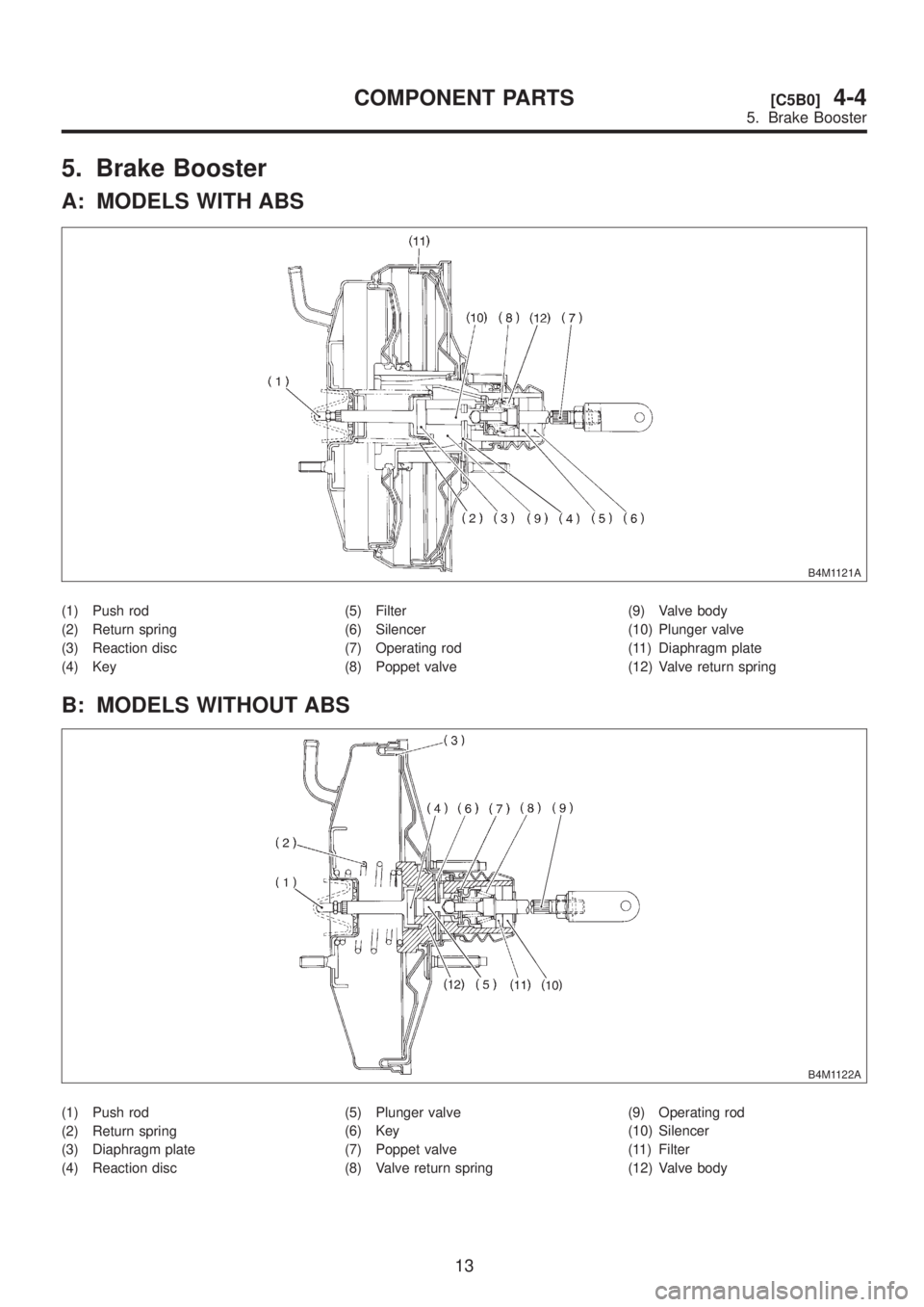
5. Brake Booster
A: MODELS WITH ABS
B4M1121A
(1) Push rod
(2) Return spring
(3) Reaction disc
(4) Key(5) Filter
(6) Silencer
(7) Operating rod
(8) Poppet valve(9) Valve body
(10) Plunger valve
(11) Diaphragm plate
(12) Valve return spring
B: MODELS WITHOUT ABS
B4M1122A
(1) Push rod
(2) Return spring
(3) Diaphragm plate
(4) Reaction disc(5) Plunger valve
(6) Key
(7) Poppet valve
(8) Valve return spring(9) Operating rod
(10) Silencer
(11) Filter
(12) Valve body
13
[C5B0]4-4COMPONENT PARTS
5. Brake Booster
Page 935 of 1456
4) Within 0.5 seconds after the ABS warning light
goes out, depress the brake pedal and hold it
immediately after ignition switch is turned to ON.
CAUTION:
Do not depress the clutch pedal.
NOTE:
IWhen the ignition switch is set to on, the brake
pedal must not be depressed.
IEngine must not operate.
5) After completion of ABS sequence control, turn
ignition switch OFF.
2. OPERATIONAL GUIDELINES OF THE
ABS SEQUENCE CONTROL WITH
SELECT MONITOR
NOTE:
IIn the event of any trouble, the sequence con-
trol may not be operative. In such a case, activate
the sequence control, referring to ªOPERATIONAL
GUIDELINES OF THE ABS SEQUENCE CON-
TROL WITH DIAGNOSIS CONNECTORº.
IWhen the diagnosis terminal is connected to the
diagnosis connector, the sequence control will not
operate.
1) Connect select monitor to data link connector
beside driver's seat instrument panel lower cover.
2) Turn ignition switch ON.
3) Turn select monitor switch ON.
4) Put select monitor to {ABS/TCS} mode.
5) When {Function check sequence} is selected,
`ABS sequence control' will start.
6) The message `Press Brake Pedal Firmly' is dis-
played as follows:
(1) When using the brake tester, depress brake
pedal with braking force of 981 N (100 kg, 221
lb).
(2) When using the pressure gauge, depress
brake pedal so as to make the pressure gauge
indicate 3,432 kPa (35 kg/cm
2, 498 psi).
CAUTION:
Do not depress the clutch pedal.
7) When the message ªPress YESº is displayed,
press YES key.
8) Operation points will be displayed on select
monitor.
3. CONDITIONS FOR COMPLETION OF
ABS SEQUENCE CONTROL
When the following conditions develop, the ABS
sequence control stops and ABS operation is
returned to the normal control mode.
1) When the speed of at least one wheel reaches
10 km/h (6 MPH).
2) When terminal No. 3 or No. 6 are separated
from diagnosis terminals. (When select monitor is
not used.)
3) When the brake pedal is released during
sequence control and the braking lamp switch is
set to off.
4) When brake pedal is depressed after ignition
key is turned to ON, and before ABS warning light
goes out. (When select monitor is not used.)
5) When brake pedal is not depressed after igni-
tion key is turned to ON, and within 0.5 seconds
after ABS warning light goes out. (When select
monitor is not used.)
6) After completion of the sequence control.
7) When malfunction is detected. (When select
monitor is used.)
58
4-4[W15D2]SERVICE PROCEDURE
15. ABS Control Module and Hydraulic Control Unit (ABSCM&H/U)
Page 936 of 1456
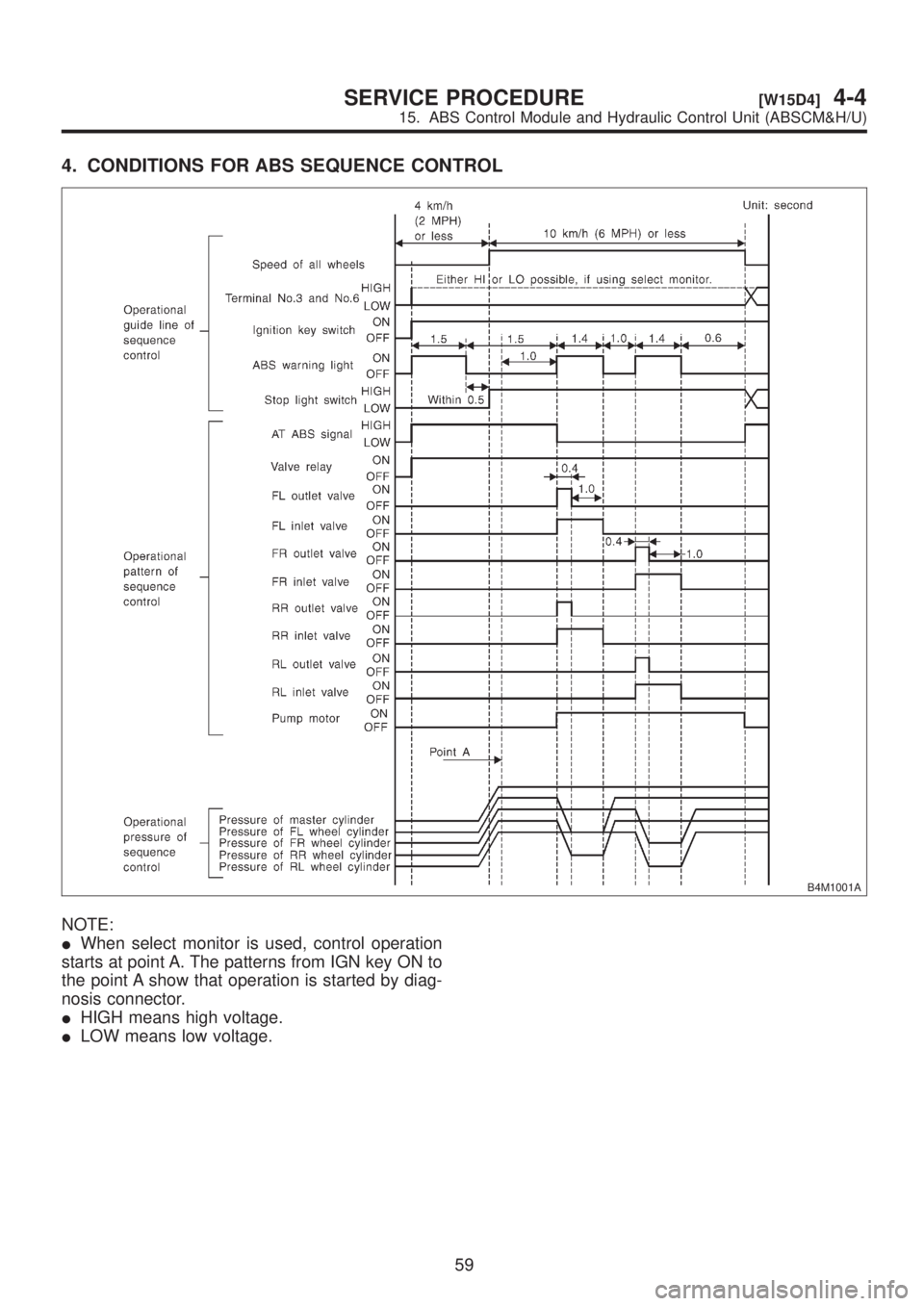
4. CONDITIONS FOR ABS SEQUENCE CONTROL
B4M1001A
NOTE:
IWhen select monitor is used, control operation
starts at point A. The patterns from IGN key ON to
the point A show that operation is started by diag-
nosis connector.
IHIGH means high voltage.
ILOW means low voltage.
59
[W15D4]4-4SERVICE PROCEDURE
15. ABS Control Module and Hydraulic Control Unit (ABSCM&H/U)
Page 997 of 1456
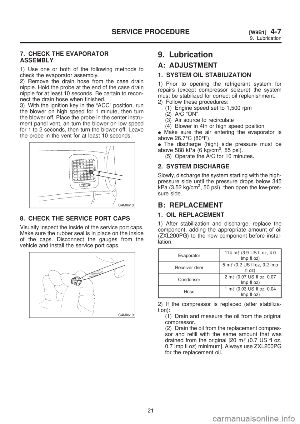
7. CHECK THE EVAPORATOR
ASSEMBLY
1) Use one or both of the following methods to
check the evaporator assembly.
2) Remove the drain hose from the case drain
nipple. Hold the probe at the end of the case drain
nipple for at least 10 seconds. Be certain to recon-
nect the drain hose when finished.
3) With the ignition key in the ªACCº position, run
the blower on high speed for 1 minute, then turn
the blower off. Place the probe in the center instru-
ment panel vent, an turn the blower on low speed
for 1 to 2 seconds, then turn the blower off. Leave
the probe in the vent for at least 10 seconds.
G4M0618
8. CHECK THE SERVICE PORT CAPS
Visually inspect the inside of the service port caps.
Make sure the rubber seal is in place on the inside
of the caps. Disconnect the gauges from the
vehicle and install the service port caps.
G4M0619
9. Lubrication
A: ADJUSTMENT
1. SYSTEM OIL STABILIZATION
1) Prior to opening the refrigerant system for
repairs (except compressor seizure) the system
must be stabilized for correct oil replenishment.
2) Follow these procedures:
(1) Engine speed set to 1,500 rpm
(2) A/C ªONº
(3) Air source to recirculate
(4) Blower in 4th or high speed position
IMake sure the air entering the evaporator is
above 26.7ÉC (80ÉF).
IThe discharge (high) side pressure must be
above 588 kPa (6 kg/cm
2, 85 psi).
(5) Operate the A/C for 10 minutes.
2. SYSTEM DISCHARGE
Slowly, discharge the system starting with the high-
pressure side until the pressure drops below 345
kPa (3.52 kg/cm
2, 50 psi), then open the low-pres-
sure side.
B: REPLACEMENT
1. OIL REPLACEMENT
1) After stabilization and discharge, replace the
component, adding the appropriate amount of oil
(ZXL200PG) to the new component before instal-
lation.
Evaporator11 4 m(3.9 US fl oz, 4.0
Imp fl oz)
Receiver drier5m(0.2 US fl oz, 0.2 Imp
fl oz)
Condenser2m(0.07 US fl oz, 0.07
Imp fl oz)
Hose1m(0.03 US fl oz, 0.04
Imp fl oz)
2) If the compressor is replaced (after stabiliza-
tion):
(1) Drain and measure the oil from the original
compressor.
(2) Drain the oil from the replacement compres-
sor and refill with the same amount that was
drained from the original [20 m(0.7 US fl oz,
0.7 Imp fl oz) minimum]. Always use ZXL200PG
for the replacement oil.
21
[W9B1]4-7SERVICE PROCEDURE
9. Lubrication
Page 998 of 1456
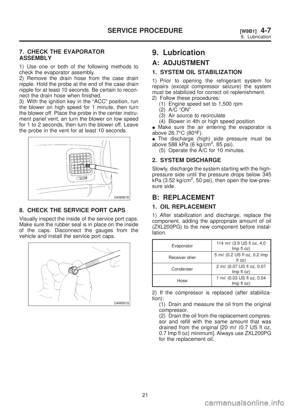
7. CHECK THE EVAPORATOR
ASSEMBLY
1) Use one or both of the following methods to
check the evaporator assembly.
2) Remove the drain hose from the case drain
nipple. Hold the probe at the end of the case drain
nipple for at least 10 seconds. Be certain to recon-
nect the drain hose when finished.
3) With the ignition key in the ªACCº position, run
the blower on high speed for 1 minute, then turn
the blower off. Place the probe in the center instru-
ment panel vent, an turn the blower on low speed
for 1 to 2 seconds, then turn the blower off. Leave
the probe in the vent for at least 10 seconds.
G4M0618
8. CHECK THE SERVICE PORT CAPS
Visually inspect the inside of the service port caps.
Make sure the rubber seal is in place on the inside
of the caps. Disconnect the gauges from the
vehicle and install the service port caps.
G4M0619
9. Lubrication
A: ADJUSTMENT
1. SYSTEM OIL STABILIZATION
1) Prior to opening the refrigerant system for
repairs (except compressor seizure) the system
must be stabilized for correct oil replenishment.
2) Follow these procedures:
(1) Engine speed set to 1,500 rpm
(2) A/C ªONº
(3) Air source to recirculate
(4) Blower in 4th or high speed position
IMake sure the air entering the evaporator is
above 26.7ÉC (80ÉF).
IThe discharge (high) side pressure must be
above 588 kPa (6 kg/cm
2, 85 psi).
(5) Operate the A/C for 10 minutes.
2. SYSTEM DISCHARGE
Slowly, discharge the system starting with the high-
pressure side until the pressure drops below 345
kPa (3.52 kg/cm
2, 50 psi), then open the low-pres-
sure side.
B: REPLACEMENT
1. OIL REPLACEMENT
1) After stabilization and discharge, replace the
component, adding the appropriate amount of oil
(ZXL200PG) to the new component before instal-
lation.
Evaporator11 4 m(3.9 US fl oz, 4.0
Imp fl oz)
Receiver drier5m(0.2 US fl oz, 0.2 Imp
fl oz)
Condenser2m(0.07 US fl oz, 0.07
Imp fl oz)
Hose1m(0.03 US fl oz, 0.04
Imp fl oz)
2) If the compressor is replaced (after stabiliza-
tion):
(1) Drain and measure the oil from the original
compressor.
(2) Drain the oil from the replacement compres-
sor and refill with the same amount that was
drained from the original [20 m(0.7 US fl oz,
0.7 Imp fl oz) minimum]. Always use ZXL200PG
for the replacement oil.
21
[W9B1]4-7SERVICE PROCEDURE
9. Lubrication
Page 1062 of 1456
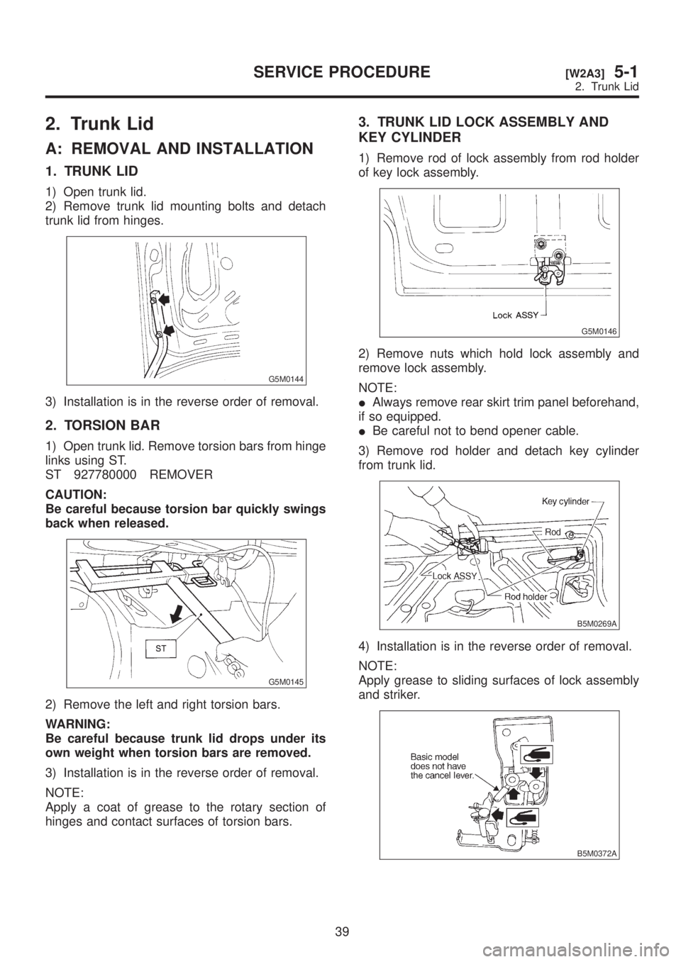
2. Trunk Lid
A: REMOVAL AND INSTALLATION
1. TRUNK LID
1) Open trunk lid.
2) Remove trunk lid mounting bolts and detach
trunk lid from hinges.
G5M0144
3) Installation is in the reverse order of removal.
2. TORSION BAR
1) Open trunk lid. Remove torsion bars from hinge
links using ST.
ST 927780000 REMOVER
CAUTION:
Be careful because torsion bar quickly swings
back when released.
G5M0145
2) Remove the left and right torsion bars.
WARNING:
Be careful because trunk lid drops under its
own weight when torsion bars are removed.
3) Installation is in the reverse order of removal.
NOTE:
Apply a coat of grease to the rotary section of
hinges and contact surfaces of torsion bars.
3. TRUNK LID LOCK ASSEMBLY AND
KEY CYLINDER
1) Remove rod of lock assembly from rod holder
of key lock assembly.
G5M0146
2) Remove nuts which hold lock assembly and
remove lock assembly.
NOTE:
IAlways remove rear skirt trim panel beforehand,
if so equipped.
IBe careful not to bend opener cable.
3) Remove rod holder and detach key cylinder
from trunk lid.
B5M0269A
4) Installation is in the reverse order of removal.
NOTE:
Apply grease to sliding surfaces of lock assembly
and striker.
B5M0372A
39
[W2A3]5-1SERVICE PROCEDURE
2. Trunk Lid
Page 1107 of 1456
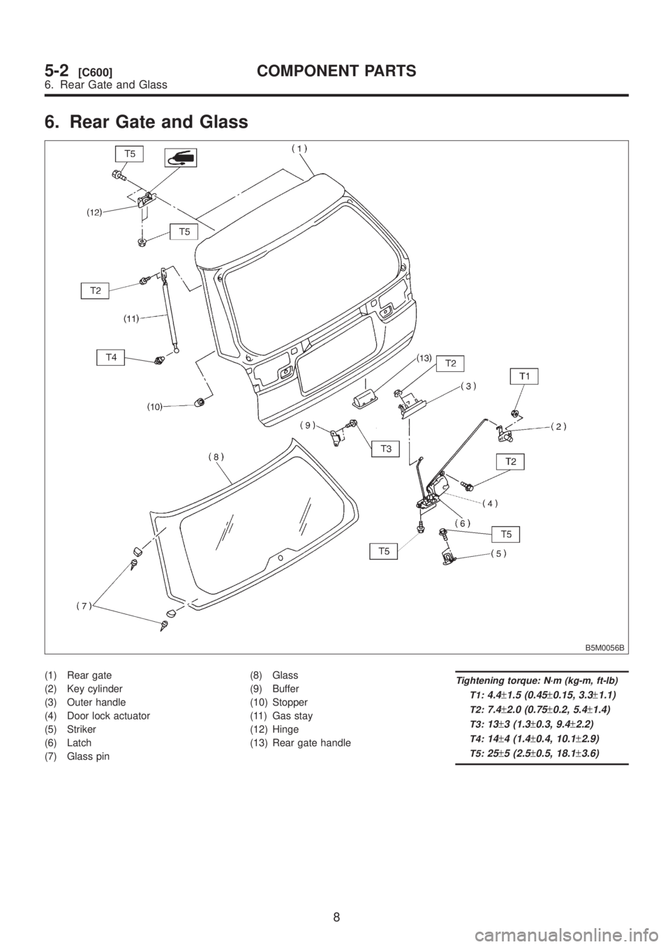
6. Rear Gate and Glass
B5M0056B
(1) Rear gate
(2) Key cylinder
(3) Outer handle
(4) Door lock actuator
(5) Striker
(6) Latch
(7) Glass pin(8) Glass
(9) Buffer
(10) Stopper
(11) Gas stay
(12) Hinge
(13) Rear gate handleTightening torque: N´m (kg-m, ft-lb)
T1:
4.4±1.5 (0.45±0.15, 3.3±1.1)
T2:7.4±2.0 (0.75±0.2, 5.4±1.4)
T3:13±3 (1.3±0.3, 9.4±2.2)
T4:14±4 (1.4±0.4, 10.1±2.9)
T5:25±5 (2.5±0.5, 18.1±3.6)
8
5-2[C600]COMPONENT PARTS
6. Rear Gate and Glass
Page 1116 of 1456
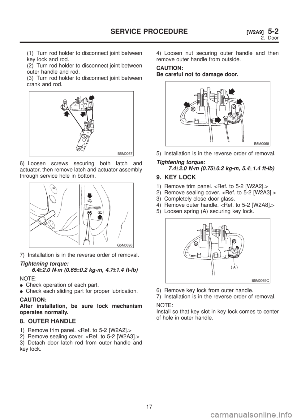
(1) Turn rod holder to disconnect joint between
key lock and rod.
(2) Turn rod holder to disconnect joint between
outer handle and rod.
(3) Turn rod holder to disconnect joint between
crank and rod.
B5M0067
6) Loosen screws securing both latch and
actuator, then remove latch and actuator assembly
through service hole in bottom.
G5M0396
7) Installation is in the reverse order of removal.
Tightening torque:
6.4
±2.0 N´m (0.65±0.2 kg-m, 4.7±1.4 ft-lb)
NOTE:
ICheck operation of each part.
ICheck each sliding part for proper lubrication.
CAUTION:
After installation, be sure lock mechanism
operates normally.
8. OUTER HANDLE
1) Remove trim panel.
2) Remove sealing cover.
3) Detach door latch rod from outer handle and
key lock.4) Loosen nut securing outer handle and then
remove outer handle from outside.
CAUTION:
Be careful not to damage door.
B5M0068
5) Installation is in the reverse order of removal.
Tightening torque:
7.4
±2.0 N´m (0.75±0.2 kg-m, 5.4±1.4 ft-lb)
9. KEY LOCK
1) Remove trim panel.
2) Remove sealing cover.
3) Completely close door glass.
4) Remove outer handle.
5) Loosen spring (A) securing key lock.
B5M0069C
6) Remove key lock from outer handle.
7) Installation is in the reverse order of removal.
NOTE:
Install so that key slot in key lock comes to center
of hole in outer handle.
17
[W2A9]5-2SERVICE PROCEDURE
2. Door