ESP SUBARU LEGACY 1999 Service Repair Manual
[x] Cancel search | Manufacturer: SUBARU, Model Year: 1999, Model line: LEGACY, Model: SUBARU LEGACY 1999Pages: 1456, PDF Size: 59.93 MB
Page 47 of 1456
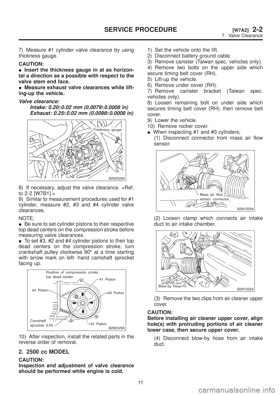
7) Measure #1 cylinder valve clearance by using
thickness gauge.
CAUTION:
IInsert the thickness gauge in at as horizon-
tal a direction as a possible with respect to the
valve stem end face.
IMeasure exhaust valve clearances while lift-
ing-up the vehicle.
Valve clearance:
Intake: 0.20
±0.02 mm (0.0079±0.0008 in)
Exhaust: 0.25
±0.02 mm (0.0098±0.0008 in)
B2M2028A
8) If necessary, adjust the valve clearance.
9) Similar to measurement procedures used for #1
cylinder, measure #2, #3 and #4 cylinder valve
clearances.
NOTE:
IBe sure to set cylinder pistons to their respective
top dead centers on the compression stroke before
measuring valve clearances.
ITo set #3, #2 and #4 cylinder pistons to their top
dead centers on the compression stroke, turn
crankshaft pulley clockwise 90É at a time starting
with arrow mark on left- hand camshaft sprocket
facing up.
B2M2029A
10) After inspection, install the related parts in the
reverse order of removal.
2. 2500 cc MODEL
CAUTION:
Inspection and adjustment of valve clearance
should be performed while engine is cold.1) Set the vehicle onto the lift.
2) Disconnect battery ground cable.
3) Remove canister (Taiwan spec. vehicles only).
4) Remove two bolts on the upper side which
secure timing belt cover (RH).
5) Lift-up the vehicle.
6) Remove under cover (RH).
7) Remove canister bracket (Taiwan spec.
vehicles only).
8) Loosen remaining bolt on under side which
secures timing belt cover (RH), then remove belt
cover.
9) Lower the vehicle.
10) Remove rocker cover.
IWhen inspecting #1 and #3 cylinders;
(1) Disconnect connector from mass air flow
sensor.
B2M1225A
(2) Loosen clamp which connects air intake
duct to air intake chamber.
B2M1226A
(3) Remove the two clips from air cleaner upper
cover.
CAUTION:
Before installing air cleaner upper cover, align
hole(s) with protruding portions of air cleaner
lower case, then secure upper cover.
(4) Disconnect blow-by hose from air intake
duct.
11
[W7A2]2-2SERVICE PROCEDURE
7. Valve Clearance
Page 48 of 1456
(5) Remove air intake duct and air cleaner
upper cover as a unit.
B2M1227
(6) Remove air cleaner element.
(7) Remove air cleaner lower case.
S2M0179
(8) Disconnect spark plug cords from spark
plugs (#1 and #3 cylinders).
(9) Place suitable container under the vehicle.
(10) Disconnect PCV hose from rocker cover
(RH).
(11) Remove bolts, then remove rocker cover
(RH).
IWhen inspecting # 2 and #4 cylinders;
(1) Disconnect battery cables, and then
remove battery and battery carrier.
(2) Disconnect washer motor connectors.
(3) Disconnect washer hoses from washer
motors, then plug connections with suitable
caps.
(4) Remove washer tank.
(5) Disconnect spark plug cords from spark
plugs (#2 and #4 cylinders).
(6) Remove under cover (LH).
(7) Place suitable container under the vehicle.
(8) Disconnect PCV hose from rocker cover
(LH).
(9) Remove bolts, then remove rocker cover
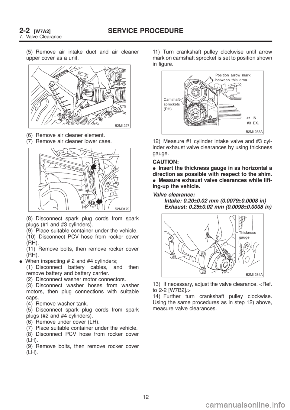
(LH).11) Turn crankshaft pulley clockwise until arrow
mark on camshaft sprocket is set to position shown
in figure.
B2M1233A
12) Measure #1 cylinder intake valve and #3 cyl-
inder exhaust valve clearances by using thickness
gauge.
CAUTION:
IInsert the thickness gauge in as horizontal a
direction as possible with respect to the shim.
IMeasure exhaust valve clearances while lift-
ing-up the vehicle.
Valve clearance:
Intake: 0.20
±0.02 mm (0.0079±0.0008 in)
Exhaust: 0.25
±0.02 mm (0.0098±0.0008 in)
B2M1234A
13) If necessary, adjust the valve clearance.
14) Further turn crankshaft pulley clockwise.
Using the same procedures as in step 12) above,
measure valve clearances.
12
2-2[W7A2]SERVICE PROCEDURE
7. Valve Clearance
Page 50 of 1456
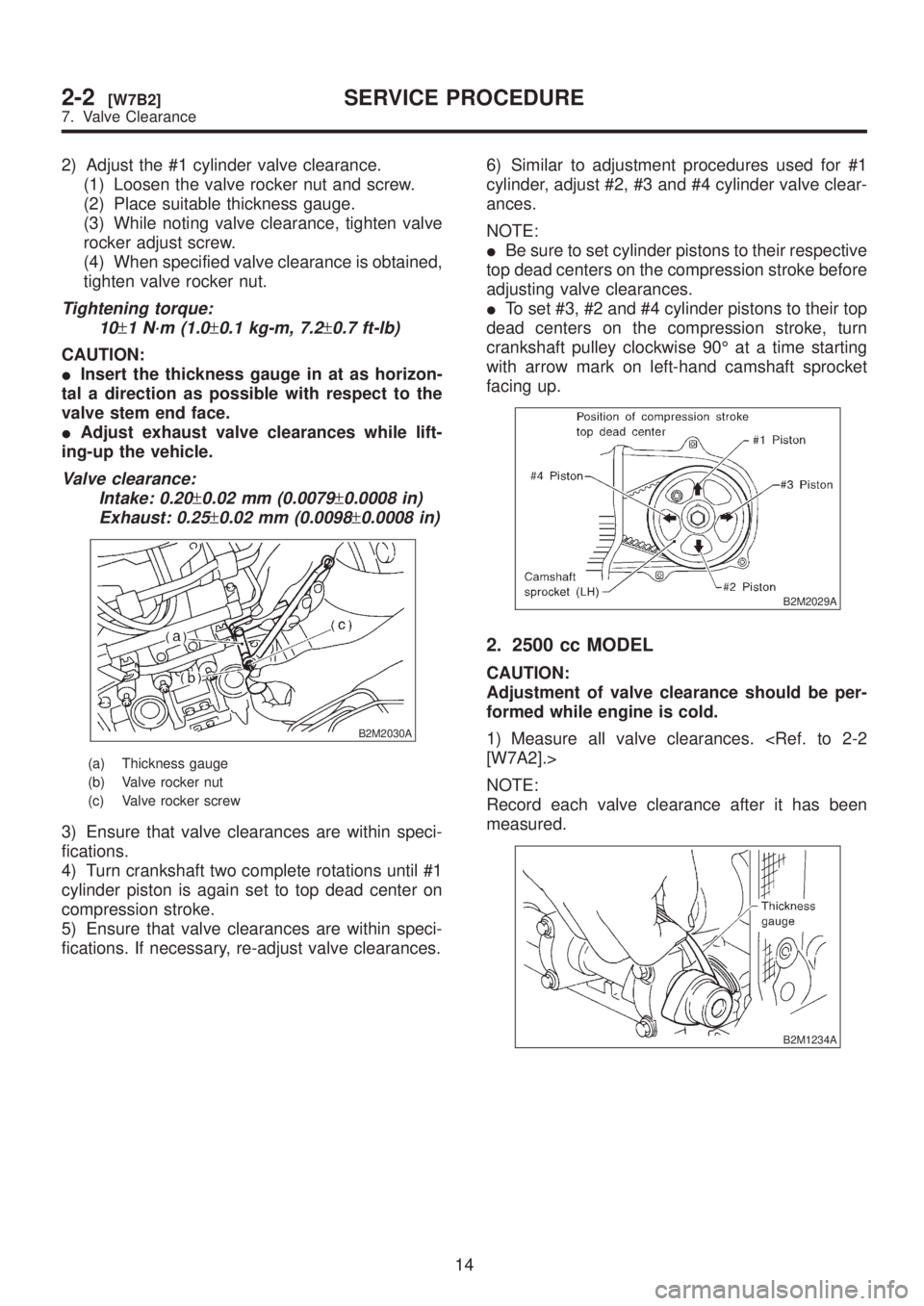
2) Adjust the #1 cylinder valve clearance.
(1) Loosen the valve rocker nut and screw.
(2) Place suitable thickness gauge.
(3) While noting valve clearance, tighten valve
rocker adjust screw.
(4) When specified valve clearance is obtained,
tighten valve rocker nut.
Tightening torque:
10
±1 N´m (1.0±0.1 kg-m, 7.2±0.7 ft-lb)
CAUTION:
IInsert the thickness gauge in at as horizon-
tal a direction as possible with respect to the
valve stem end face.
IAdjust exhaust valve clearances while lift-
ing-up the vehicle.
Valve clearance:
Intake: 0.20
±0.02 mm (0.0079±0.0008 in)
Exhaust: 0.25
±0.02 mm (0.0098±0.0008 in)
B2M2030A
(a) Thickness gauge
(b) Valve rocker nut
(c) Valve rocker screw
3) Ensure that valve clearances are within speci-
fications.
4) Turn crankshaft two complete rotations until #1
cylinder piston is again set to top dead center on
compression stroke.
5) Ensure that valve clearances are within speci-
fications. If necessary, re-adjust valve clearances.6) Similar to adjustment procedures used for #1
cylinder, adjust #2, #3 and #4 cylinder valve clear-
ances.
NOTE:
IBe sure to set cylinder pistons to their respective
top dead centers on the compression stroke before
adjusting valve clearances.
ITo set #3, #2 and #4 cylinder pistons to their top
dead centers on the compression stroke, turn
crankshaft pulley clockwise 90É at a time starting
with arrow mark on left-hand camshaft sprocket
facing up.
B2M2029A
2. 2500 cc MODEL
CAUTION:
Adjustment of valve clearance should be per-
formed while engine is cold.
1) Measure all valve clearances.
NOTE:
Record each valve clearance after it has been
measured.
B2M1234A
14
2-2[W7B2]SERVICE PROCEDURE
7. Valve Clearance
Page 54 of 1456
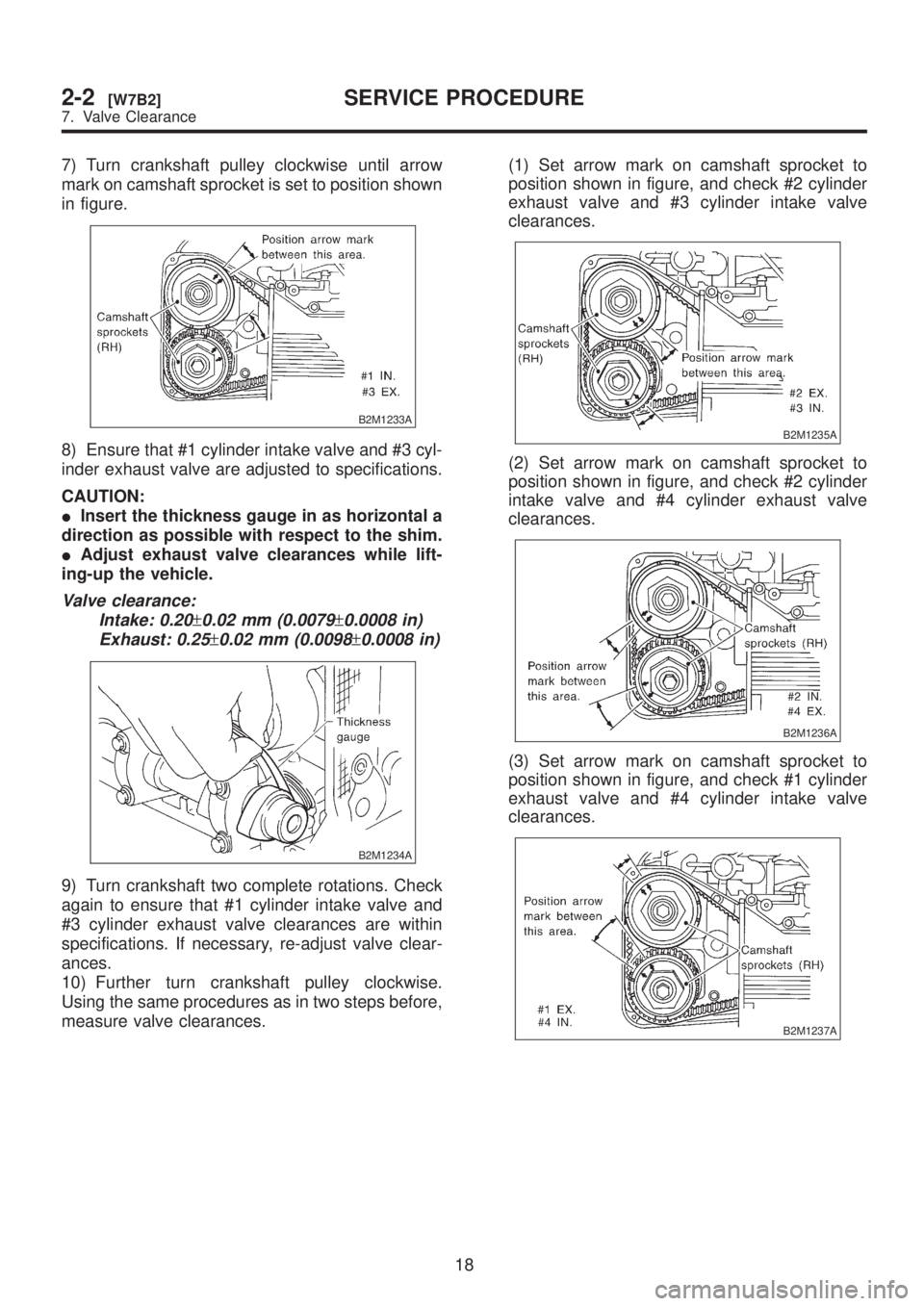
7) Turn crankshaft pulley clockwise until arrow
mark on camshaft sprocket is set to position shown
in figure.
B2M1233A
8) Ensure that #1 cylinder intake valve and #3 cyl-
inder exhaust valve are adjusted to specifications.
CAUTION:
IInsert the thickness gauge in as horizontal a
direction as possible with respect to the shim.
IAdjust exhaust valve clearances while lift-
ing-up the vehicle.
Valve clearance:
Intake: 0.20
±0.02 mm (0.0079±0.0008 in)
Exhaust: 0.25
±0.02 mm (0.0098±0.0008 in)
B2M1234A
9) Turn crankshaft two complete rotations. Check
again to ensure that #1 cylinder intake valve and
#3 cylinder exhaust valve clearances are within
specifications. If necessary, re-adjust valve clear-
ances.
10) Further turn crankshaft pulley clockwise.
Using the same procedures as in two steps before,
measure valve clearances.(1) Set arrow mark on camshaft sprocket to
position shown in figure, and check #2 cylinder
exhaust valve and #3 cylinder intake valve
clearances.
B2M1235A
(2) Set arrow mark on camshaft sprocket to
position shown in figure, and check #2 cylinder
intake valve and #4 cylinder exhaust valve
clearances.
B2M1236A
(3) Set arrow mark on camshaft sprocket to
position shown in figure, and check #1 cylinder
exhaust valve and #4 cylinder intake valve
clearances.
B2M1237A
18
2-2[W7B2]SERVICE PROCEDURE
7. Valve Clearance
Page 98 of 1456
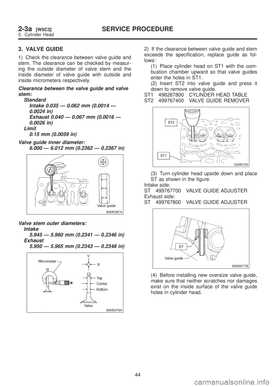
3. VALVE GUIDE
1) Check the clearance between valve guide and
stem. The clearance can be checked by measur-
ing the outside diameter of valve stem and the
inside diameter of valve guide with outside and
inside micrometers respectively.
Clearance between the valve guide and valve
stem:
Standard
Intake 0.035 Ð 0.062 mm (0.0014 Ð
0.0024 in)
Exhaust 0.040 Ð 0.067 mm (0.0016 Ð
0.0026 in)
Limit
0.15 mm (0.0059 in)
Valve guide inner diameter:
6.000 Ð 6.012 mm (0.2362 Ð 0.2367 in)
B2M0387A
Valve stem outer diameters:
Intake
5.945 Ð 5.960 mm (0.2341 Ð 0.2346 in)
Exhaust
5.950 Ð 5.965 mm (0.2343 Ð 0.2348 in)
B2M0076A
2) If the clearance between valve guide and stem
exceeds the specification, replace guide as fol-
lows:
(1) Place cylinder head on ST1 with the com-
bustion chamber upward so that valve guides
enter the holes in ST1.
(2) Insert ST2 into valve guide and press it
down to remove valve guide.
ST1 498267800 CYLINDER HEAD TABLE
ST2 499767400 VALVE GUIDE REMOVER
G2M0150
(3) Turn cylinder head upside down and place
ST as shown in the figure.
Intake side:
ST 499767700 VALVE GUIDE ADJUSTER
Exhaust side:
ST 499767800 VALVE GUIDE ADJUSTER
B2M0077B
(4) Before installing new oversize valve guide,
make sure that neither scratches nor damages
exist on the inside surface of the valve guide
holes in cylinder head.
44
2-3a[W5C3]SERVICE PROCEDURE
5. Cylinder Head
Page 110 of 1456
4) Remove crankshaft together with connecting
rod.
5) Remove crankshaft bearings from cylinder
block using hammer handle.
CAUTION:
Do not confuse combination of crankshaft
bearings. Press bearing at the end opposite to
locking lip.6) Draw out each piston from cylinder block using
wooden bar or hammer handle.
CAUTION:
Do not confuse combination of piston and cyl-
inder.
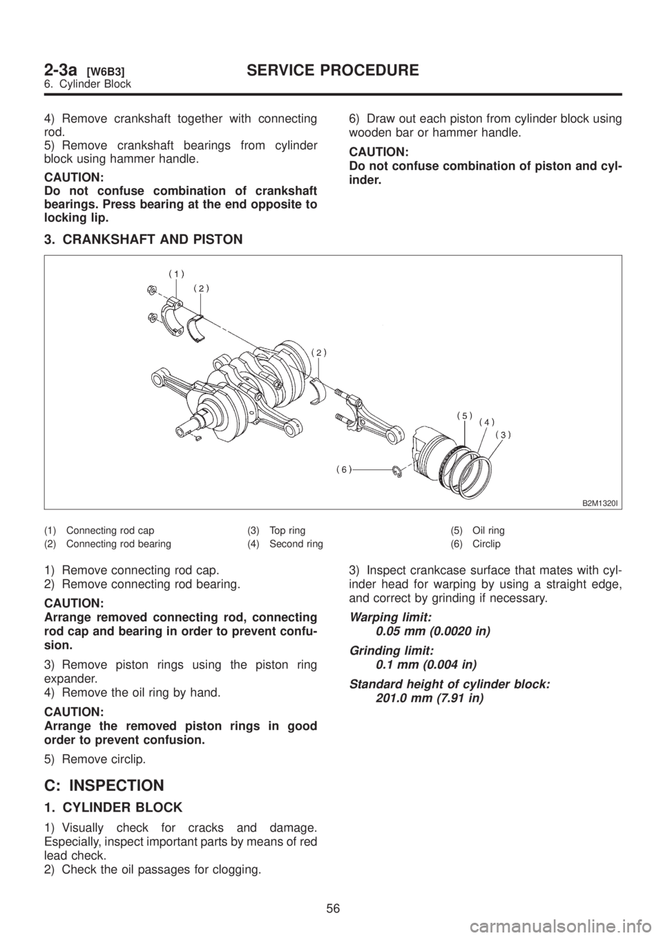
3. CRANKSHAFT AND PISTON
B2M1320I
(1) Connecting rod cap
(2) Connecting rod bearing(3) Top ring
(4) Second ring(5) Oil ring
(6) Circlip
1) Remove connecting rod cap.
2) Remove connecting rod bearing.
CAUTION:
Arrange removed connecting rod, connecting
rod cap and bearing in order to prevent confu-
sion.
3) Remove piston rings using the piston ring
expander.
4) Remove the oil ring by hand.
CAUTION:
Arrange the removed piston rings in good
order to prevent confusion.
5) Remove circlip.
C: INSPECTION
1. CYLINDER BLOCK
1) Visually check for cracks and damage.
Especially, inspect important parts by means of red
lead check.
2) Check the oil passages for clogging.3) Inspect crankcase surface that mates with cyl-
inder head for warping by using a straight edge,
and correct by grinding if necessary.
Warping limit:
0.05 mm (0.0020 in)
Grinding limit:
0.1 mm (0.004 in)
Standard height of cylinder block:
201.0 mm (7.91 in)
56
2-3a[W6B3]SERVICE PROCEDURE
6. Cylinder Block
Page 118 of 1456
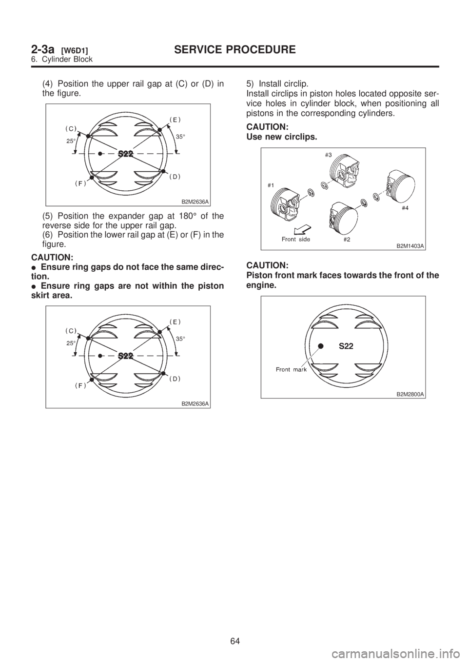
(4) Position the upper rail gap at (C) or (D) in
the figure.
B2M2636A
(5) Position the expander gap at 180É of the
reverse side for the upper rail gap.
(6) Position the lower rail gap at (E) or (F) in the
figure.
CAUTION:
IEnsure ring gaps do not face the same direc-
tion.
IEnsure ring gaps are not within the piston
skirt area.
B2M2636A
5) Install circlip.
Install circlips in piston holes located opposite ser-
vice holes in cylinder block, when positioning all
pistons in the corresponding cylinders.
CAUTION:
Use new circlips.
B2M1403A
CAUTION:
Piston front mark faces towards the front of the
engine.
B2M2800A
64
2-3a[W6D1]SERVICE PROCEDURE
6. Cylinder Block
Page 157 of 1456
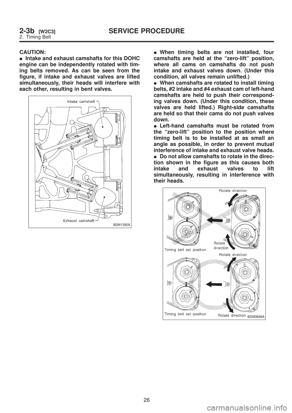
CAUTION:
IIntake and exhaust camshafts for this DOHC
engine can be independently rotated with tim-
ing belts removed. As can be seen from the
figure, if intake and exhaust valves are lifted
simultaneously, their heads will interfere with
each other, resulting in bent valves.
B2M1392A
IWhen timing belts are not installed, four
camshafts are held at the ªzero-liftº position,
where all cams on camshafts do not push
intake and exhaust valves down. (Under this
condition, all valves remain unlifted.)
IWhen camshafts are rotated to install timing
belts, #2 intake and #4 exhaust cam of left-hand
camshafts are held to push their correspond-
ing valves down. (Under this condition, these
valves are held lifted.) Right-side camshafts
are held so that their cams do not push valves
down.
ILeft-hand camshafts must be rotated from
the ªzero-liftº position to the position where
timing belt is to be installed at as small an
angle as possible, in order to prevent mutual
interference of intake and exhaust valve heads.
IDo not allow camshafts to rotate in the direc-
tion shown in the figure as this causes both
intake and exhaust valves to lift
simultaneously, resulting in interference with
their heads.
B2M0698A
26
2-3b[W2C3]SERVICE PROCEDURE
2. Timing Belt
Page 170 of 1456
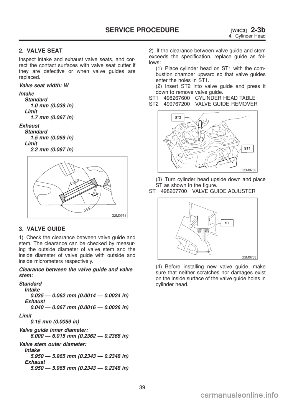
2. VALVE SEAT
Inspect intake and exhaust valve seats, and cor-
rect the contact surfaces with valve seat cutter if
they are defective or when valve guides are
replaced.
Valve seat width: W
Intake
Standard
1.0 mm (0.039 in)
Limit
1.7 mm (0.067 in)
Exhaust
Standard
1.5 mm (0.059 in)
Limit
2.2 mm (0.087 in)
G2M0761
3. VALVE GUIDE
1) Check the clearance between valve guide and
stem. The clearance can be checked by measur-
ing the outside diameter of valve stem and the
inside diameter of valve guide with outside and
inside micrometers respectively.
Clearance between the valve guide and valve
stem:
Standard
Intake
0.035 Ð 0.062 mm (0.0014 Ð 0.0024 in)
Exhaust
0.040 Ð 0.067 mm (0.0016 Ð 0.0026 in)
Limit
0.15 mm (0.0059 in)
Valve guide inner diameter:
6.000 Ð 6.015 mm (0.2362 Ð 0.2368 in)
Valve stem outer diameter:
Intake
5.950 Ð 5.965 mm (0.2343 Ð 0.2348 in)
Exhaust
5.950 Ð 5.965 mm (0.2343 Ð 0.2348 in)
2) If the clearance between valve guide and stem
exceeds the specification, replace guide as fol-
lows:
(1) Place cylinder head on ST1 with the com-
bustion chamber upward so that valve guides
enter the holes in ST1.
(2) Insert ST2 into valve guide and press it
down to remove valve guide.
ST1 498267600 CYLINDER HEAD TABLE
ST2 499767200 VALVE GUIDE REMOVER
G2M0762
(3) Turn cylinder head upside down and place
ST as shown in the figure.
ST 498267700 VALVE GUIDE ADJUSTER
G2M0763
(4) Before installing new valve guide, make
sure that neither scratches nor damages exist
on the inside surface of the valve guide holes in
cylinder head.
39
[W4C3]2-3bSERVICE PROCEDURE
4. Cylinder Head
Page 186 of 1456
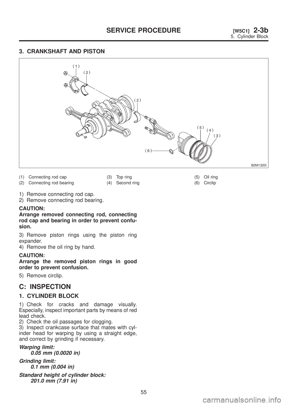
3. CRANKSHAFT AND PISTON
B2M1320I
(1) Connecting rod cap
(2) Connecting rod bearing(3) Top ring
(4) Second ring(5) Oil ring
(6) Circlip
1) Remove connecting rod cap.
2) Remove connecting rod bearing.
CAUTION:
Arrange removed connecting rod, connecting
rod cap and bearing in order to prevent confu-
sion.
3) Remove piston rings using the piston ring
expander.
4) Remove the oil ring by hand.
CAUTION:
Arrange the removed piston rings in good
order to prevent confusion.
5) Remove circlip.
C: INSPECTION
1. CYLINDER BLOCK
1) Check for cracks and damage visually.
Especially, inspect important parts by means of red
lead check.
2) Check the oil passages for clogging.
3) Inspect crankcase surface that mates with cyl-
inder head for warping by using a straight edge,
and correct by grinding if necessary.
Warping limit:
0.05 mm (0.0020 in)
Grinding limit:
0.1 mm (0.004 in)
Standard height of cylinder block:
201.0 mm (7.91 in)
55
[W5C1]2-3bSERVICE PROCEDURE
5. Cylinder Block