load capacity SUBARU LEGACY 1999 Service Repair Manual
[x] Cancel search | Manufacturer: SUBARU, Model Year: 1999, Model line: LEGACY, Model: SUBARU LEGACY 1999Pages: 1456, PDF Size: 59.93 MB
Page 654 of 1456

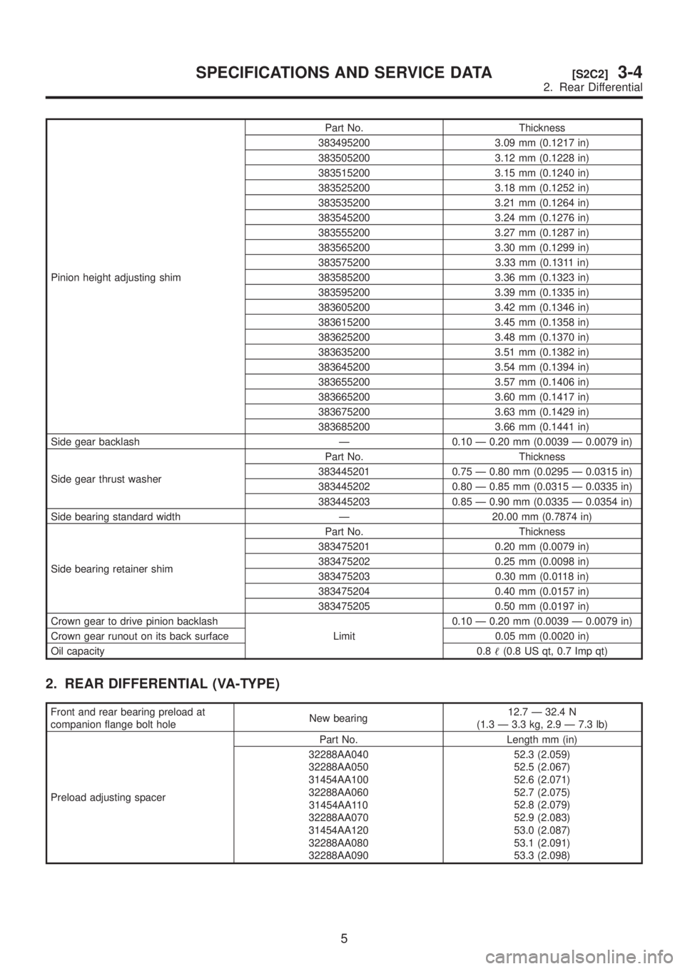
Pinion height adjusting shimPart No. Thickness
383495200 3.09 mm (0.1217 in)
383505200 3.12 mm (0.1228 in)
383515200 3.15 mm (0.1240 in)
383525200 3.18 mm (0.1252 in)
383535200 3.21 mm (0.1264 in)
383545200 3.24 mm (0.1276 in)
383555200 3.27 mm (0.1287 in)
383565200 3.30 mm (0.1299 in)
383575200 3.33 mm (0.1311 in)
383585200 3.36 mm (0.1323 in)
383595200 3.39 mm (0.1335 in)
383605200 3.42 mm (0.1346 in)
383615200 3.45 mm (0.1358 in)
383625200 3.48 mm (0.1370 in)
383635200 3.51 mm (0.1382 in)
383645200 3.54 mm (0.1394 in)
383655200 3.57 mm (0.1406 in)
383665200 3.60 mm (0.1417 in)
383675200 3.63 mm (0.1429 in)
383685200 3.66 mm (0.1441 in)
Side gear backlash Ð 0.10 Ð 0.20 mm (0.0039 Ð 0.0079 in)
Side gear thrust washerPart No. Thickness
383445201 0.75 Ð 0.80 mm (0.0295 Ð 0.0315 in)
383445202 0.80 Ð 0.85 mm (0.0315 Ð 0.0335 in)
383445203 0.85 Ð 0.90 mm (0.0335 Ð 0.0354 in)
Side bearing standard width Ð 20.00 mm (0.7874 in)
Side bearing retainer shimPart No. Thickness
383475201 0.20 mm (0.0079 in)
383475202 0.25 mm (0.0098 in)
383475203 0.30 mm (0.0118 in)
383475204 0.40 mm (0.0157 in)
383475205 0.50 mm (0.0197 in)
Crown gear to drive pinion backlash
Limit0.10 Ð 0.20 mm (0.0039 Ð 0.0079 in)
Crown gear runout on its back surface 0.05 mm (0.0020 in)
Oil capacity0.8(0.8 US qt, 0.7 Imp qt)
2. REAR DIFFERENTIAL (VA-TYPE)
Front and rear bearing preload at
companion flange bolt holeNew bearing12.7 Ð 32.4 N
(1.3 Ð 3.3 kg, 2.9 Ð 7.3 lb)
Preload adjusting spacerPart No. Length mm (in)
32288AA040
32288AA050
31454AA100
32288AA060
31454AA110
32288AA070
31454AA120
32288AA080
32288AA09052.3 (2.059)
52.5 (2.067)
52.6 (2.071)
52.7 (2.075)
52.8 (2.079)
52.9 (2.083)
53.0 (2.087)
53.1 (2.091)
53.3 (2.098)
5
[S2C2]3-4SPECIFICATIONS AND SERVICE DATA
2. Rear Differential
Page 655 of 1456

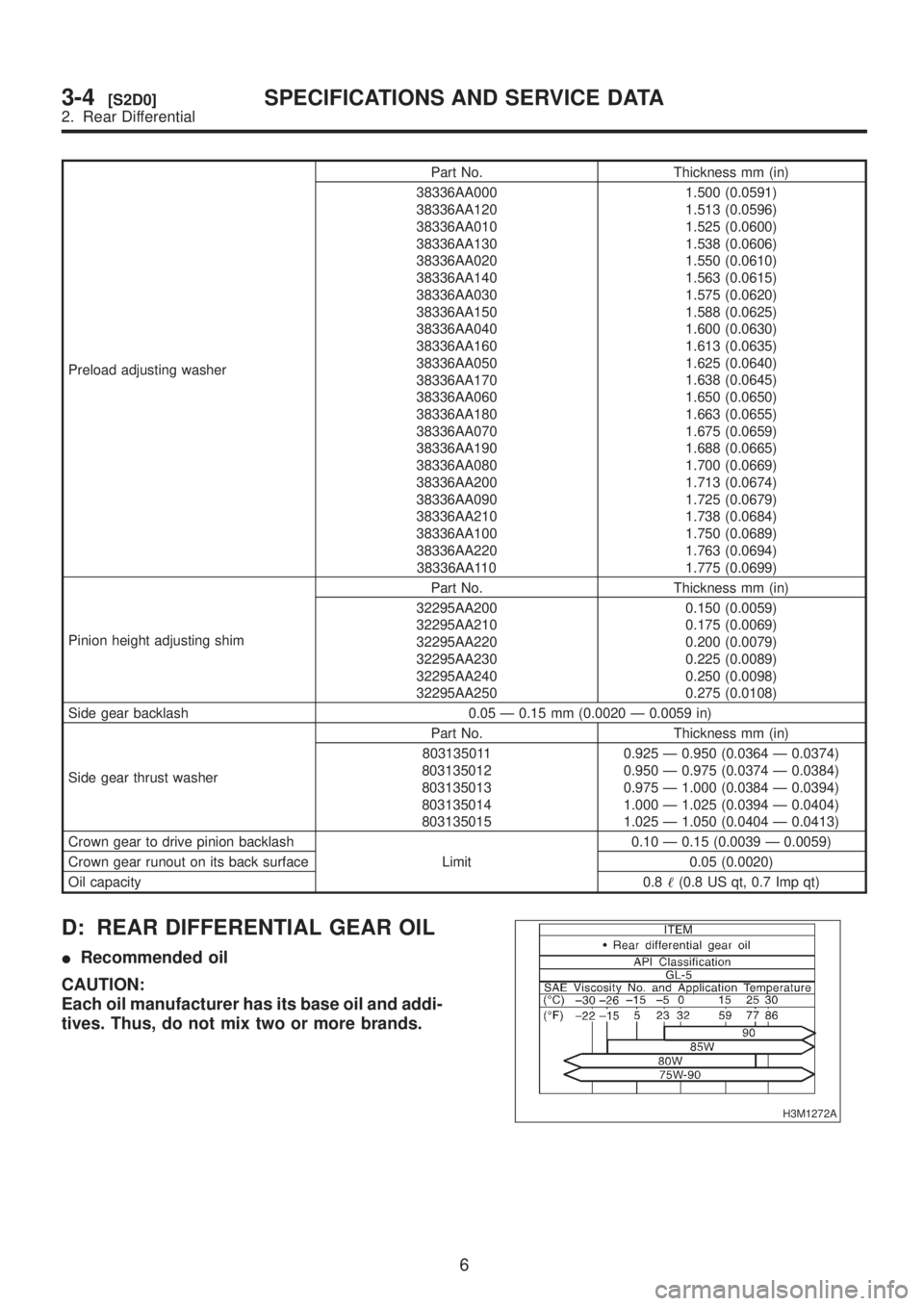
Preload adjusting washerPart No. Thickness mm (in)
38336AA000
38336AA120
38336AA010
38336AA130
38336AA020
38336AA140
38336AA030
38336AA150
38336AA040
38336AA160
38336AA050
38336AA170
38336AA060
38336AA180
38336AA070
38336AA190
38336AA080
38336AA200
38336AA090
38336AA210
38336AA100
38336AA220
38336AA1101.500 (0.0591)
1.513 (0.0596)
1.525 (0.0600)
1.538 (0.0606)
1.550 (0.0610)
1.563 (0.0615)
1.575 (0.0620)
1.588 (0.0625)
1.600 (0.0630)
1.613 (0.0635)
1.625 (0.0640)
1.638 (0.0645)
1.650 (0.0650)
1.663 (0.0655)
1.675 (0.0659)
1.688 (0.0665)
1.700 (0.0669)
1.713 (0.0674)
1.725 (0.0679)
1.738 (0.0684)
1.750 (0.0689)
1.763 (0.0694)
1.775 (0.0699)
Pinion height adjusting shimPart No. Thickness mm (in)
32295AA200
32295AA210
32295AA220
32295AA230
32295AA240
32295AA2500.150 (0.0059)
0.175 (0.0069)
0.200 (0.0079)
0.225 (0.0089)
0.250 (0.0098)
0.275 (0.0108)
Side gear backlash 0.05 Ð 0.15 mm (0.0020 Ð 0.0059 in)
Side gear thrust washerPart No. Thickness mm (in)
803135011
803135012
803135013
803135014
8031350150.925 Ð 0.950 (0.0364 Ð 0.0374)
0.950 Ð 0.975 (0.0374 Ð 0.0384)
0.975 Ð 1.000 (0.0384 Ð 0.0394)
1.000 Ð 1.025 (0.0394 Ð 0.0404)
1.025 Ð 1.050 (0.0404 Ð 0.0413)
Crown gear to drive pinion backlash
Limit0.10 Ð 0.15 (0.0039 Ð 0.0059)
Crown gear runout on its back surface 0.05 (0.0020)
Oil capacity0.8(0.8 US qt, 0.7 Imp qt)
D: REAR DIFFERENTIAL GEAR OIL
IRecommended oil
CAUTION:
Each oil manufacturer has its base oil and addi-
tives. Thus, do not mix two or more brands.
H3M1272A
6
3-4[S2D0]SPECIFICATIONS AND SERVICE DATA
2. Rear Differential
Page 994 of 1456

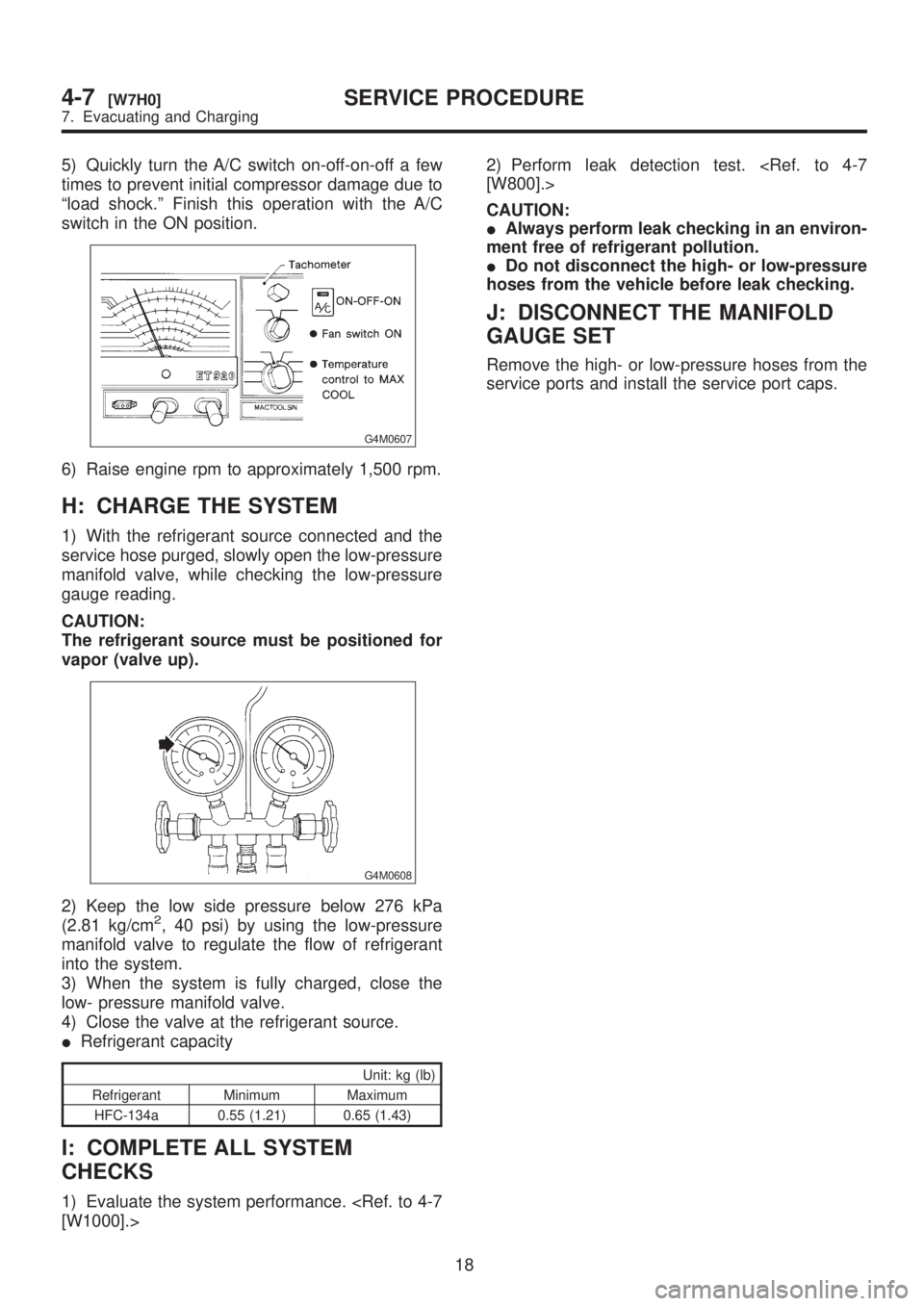
5) Quickly turn the A/C switch on-off-on-off a few
times to prevent initial compressor damage due to
ªload shock.º Finish this operation with the A/C
switch in the ON position.
G4M0607
6) Raise engine rpm to approximately 1,500 rpm.
H: CHARGE THE SYSTEM
1) With the refrigerant source connected and the
service hose purged, slowly open the low-pressure
manifold valve, while checking the low-pressure
gauge reading.
CAUTION:
The refrigerant source must be positioned for
vapor (valve up).
G4M0608
2) Keep the low side pressure below 276 kPa
(2.81 kg/cm2, 40 psi) by using the low-pressure
manifold valve to regulate the flow of refrigerant
into the system.
3) When the system is fully charged, close the
low- pressure manifold valve.
4) Close the valve at the refrigerant source.
IRefrigerant capacity
Unit: kg (lb)
Refrigerant Minimum Maximum
HFC-134a 0.55 (1.21) 0.65 (1.43)
I: COMPLETE ALL SYSTEM
CHECKS
1) Evaluate the system performance.
CAUTION:
IAlways perform leak checking in an environ-
ment free of refrigerant pollution.
IDo not disconnect the high- or low-pressure
hoses from the vehicle before leak checking.
J: DISCONNECT THE MANIFOLD
GAUGE SET
Remove the high- or low-pressure hoses from the
service ports and install the service port caps.
18
4-7[W7H0]SERVICE PROCEDURE
7. Evacuating and Charging
Page 1189 of 1456

B: TEST
1. MAGNETIC SWITCH
CAUTION:
IThe following magnetic switch tests should
be performed with specified voltage applied.
IEach test should be conducted within 3 to 5
seconds. Power to be furnished should be one-
half the rated voltage.
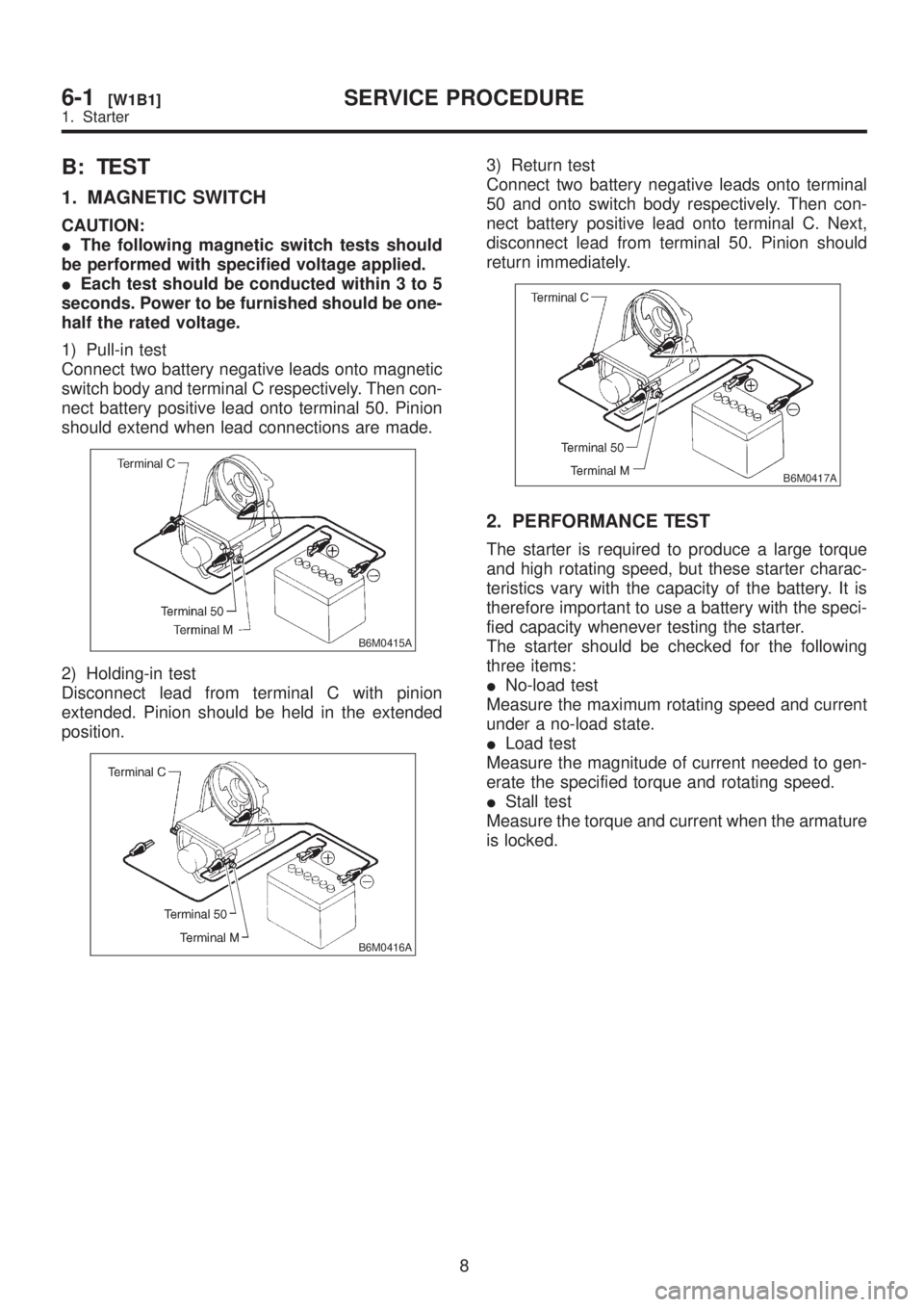
1) Pull-in test
Connect two battery negative leads onto magnetic
switch body and terminal C respectively. Then con-
nect battery positive lead onto terminal 50. Pinion
should extend when lead connections are made.
B6M0415A
2) Holding-in test
Disconnect lead from terminal C with pinion
extended. Pinion should be held in the extended
position.
B6M0416A
3) Return test
Connect two battery negative leads onto terminal
50 and onto switch body respectively. Then con-
nect battery positive lead onto terminal C. Next,
disconnect lead from terminal 50. Pinion should
return immediately.
B6M0417A
2. PERFORMANCE TEST
The starter is required to produce a large torque
and high rotating speed, but these starter charac-
teristics vary with the capacity of the battery. It is
therefore important to use a battery with the speci-
fied capacity whenever testing the starter.
The starter should be checked for the following
three items:
INo-load test
Measure the maximum rotating speed and current
under a no-load state.
ILoad test
Measure the magnitude of current needed to gen-
erate the specified torque and rotating speed.
IStall test
Measure the torque and current when the armature
is locked.
8
6-1[W1B1]SERVICE PROCEDURE
1. Starter