rear SUBARU LEGACY 1999 Service Repair Manual
[x] Cancel search | Manufacturer: SUBARU, Model Year: 1999, Model line: LEGACY, Model: SUBARU LEGACY 1999Pages: 1456, PDF Size: 59.93 MB
Page 1 of 1456
1. Front Catalytic Converter
A: REMOVAL
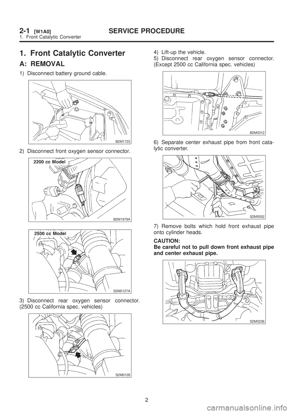
1) Disconnect battery ground cable.
B2M1723
2) Disconnect front oxygen sensor connector.
B2M1979A
S2M0127A
3) Disconnect rear oxygen sensor connector.
(2500 cc California spec. vehicles)
S2M0128
4) Lift-up the vehicle.
5) Disconnect rear oxygen sensor connector.
(Except 2500 cc California spec. vehicles)
B2M0312
6) Separate center exhaust pipe from front cata-
lytic converter.
S2M0052
7) Remove bolts which hold front exhaust pipe
onto cylinder heads.
CAUTION:
Be careful not to pull down front exhaust pipe
and center exhaust pipe.
S2M0236
2
2-1[W1A0]SERVICE PROCEDURE
1. Front Catalytic Converter
Page 2 of 1456
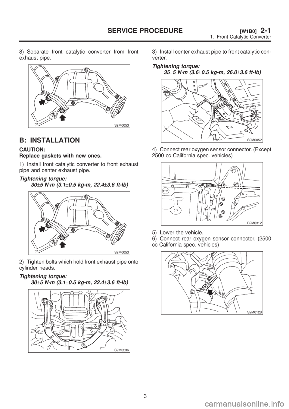
8) Separate front catalytic converter from front
exhaust pipe.
S2M0053
B: INSTALLATION
CAUTION:
Replace gaskets with new ones.
1) Install front catalytic converter to front exhaust
pipe and center exhaust pipe.
Tightening torque:
30
±5 N´m (3.1±0.5 kg-m, 22.4±3.6 ft-lb)
S2M0053
2) Tighten bolts which hold front exhaust pipe onto
cylinder heads.
Tightening torque:
30
±5 N´m (3.1±0.5 kg-m, 22.4±3.6 ft-lb)
S2M0236
3) Install center exhaust pipe to front catalytic con-
verter.
Tightening torque:
35
±5 N´m (3.6±0.5 kg-m, 26.0±3.6 ft-lb)
S2M0052
4) Connect rear oxygen sensor connector. (Except
2500 cc California spec. vehicles)
B2M0312
5) Lower the vehicle.
6) Connect rear oxygen sensor connector. (2500
cc California spec. vehicles)
S2M0128
3
[W1B0]2-1SERVICE PROCEDURE
1. Front Catalytic Converter
Page 3 of 1456
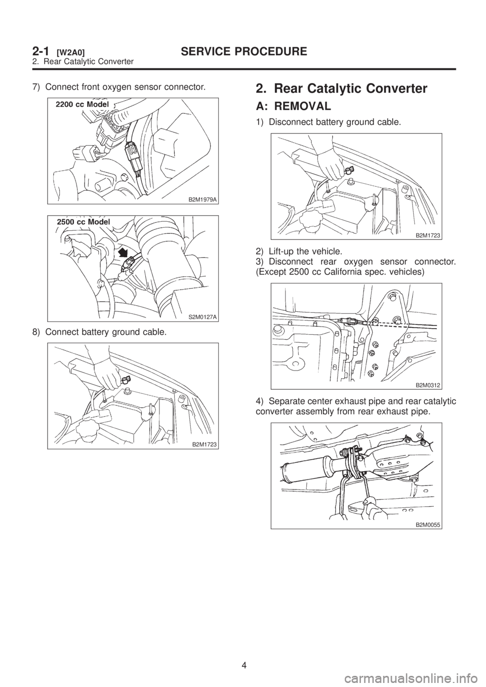
7) Connect front oxygen sensor connector.
B2M1979A
S2M0127A
8) Connect battery ground cable.
B2M1723
2. Rear Catalytic Converter
A: REMOVAL
1) Disconnect battery ground cable.
B2M1723
2) Lift-up the vehicle.
3) Disconnect rear oxygen sensor connector.
(Except 2500 cc California spec. vehicles)
B2M0312
4) Separate center exhaust pipe and rear catalytic
converter assembly from rear exhaust pipe.
B2M0055
4
2-1[W2A0]SERVICE PROCEDURE
2. Rear Catalytic Converter
Page 4 of 1456
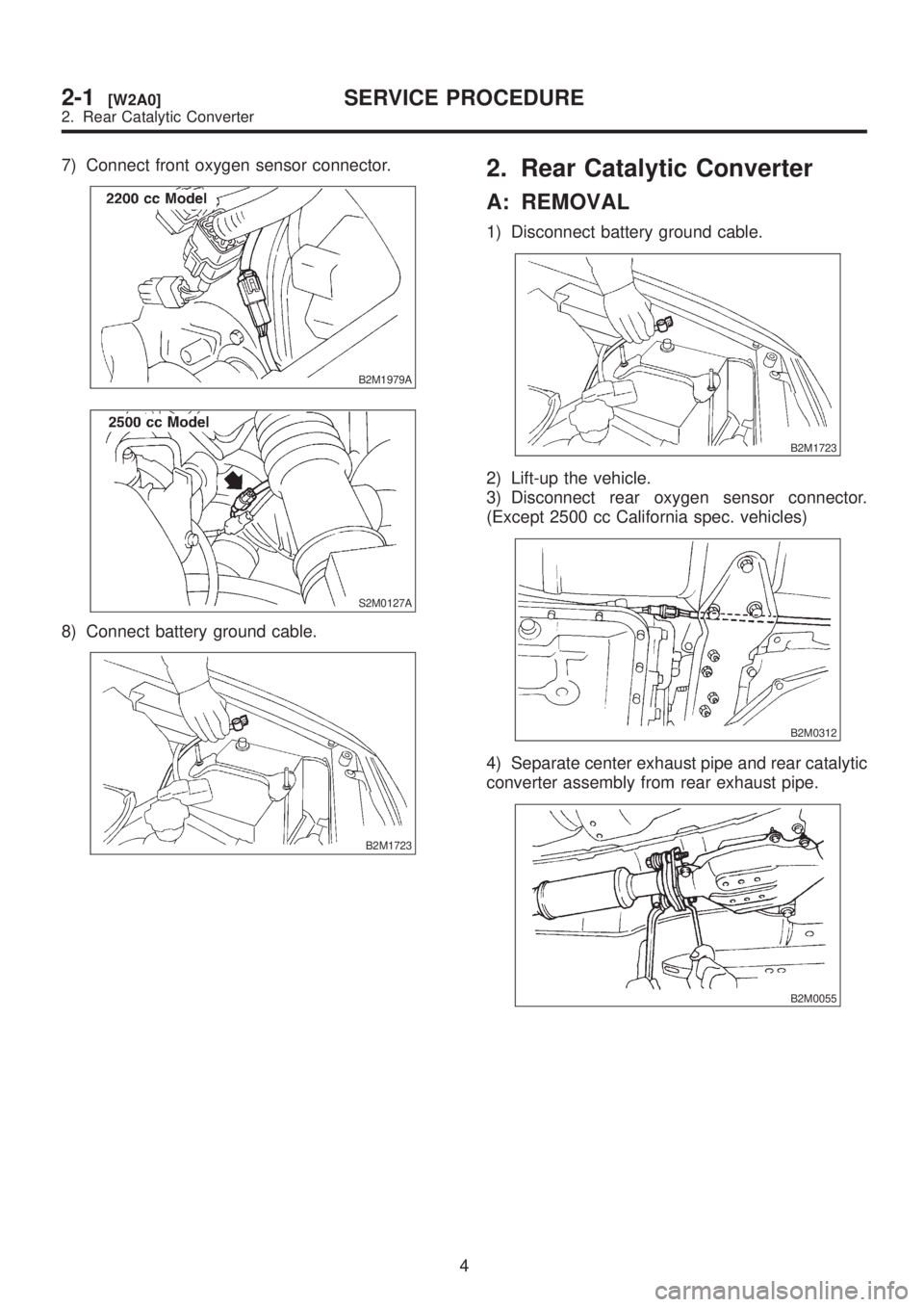
7) Connect front oxygen sensor connector.
B2M1979A
S2M0127A
8) Connect battery ground cable.
B2M1723
2. Rear Catalytic Converter
A: REMOVAL
1) Disconnect battery ground cable.
B2M1723
2) Lift-up the vehicle.
3) Disconnect rear oxygen sensor connector.
(Except 2500 cc California spec. vehicles)
B2M0312
4) Separate center exhaust pipe and rear catalytic
converter assembly from rear exhaust pipe.
B2M0055
4
2-1[W2A0]SERVICE PROCEDURE
2. Rear Catalytic Converter
Page 5 of 1456
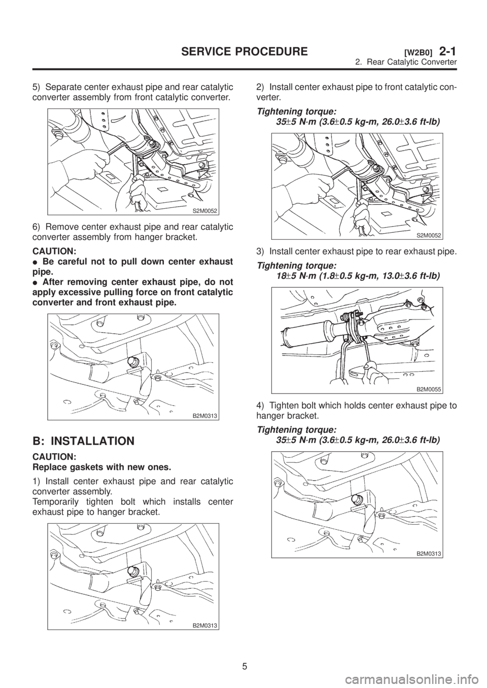
5) Separate center exhaust pipe and rear catalytic
converter assembly from front catalytic converter.
S2M0052
6) Remove center exhaust pipe and rear catalytic
converter assembly from hanger bracket.
CAUTION:
IBe careful not to pull down center exhaust
pipe.
IAfter removing center exhaust pipe, do not
apply excessive pulling force on front catalytic
converter and front exhaust pipe.
B2M0313
B: INSTALLATION
CAUTION:
Replace gaskets with new ones.
1) Install center exhaust pipe and rear catalytic
converter assembly.
Temporarily tighten bolt which installs center
exhaust pipe to hanger bracket.
B2M0313
2) Install center exhaust pipe to front catalytic con-
verter.
Tightening torque:
35
±5 N´m (3.6±0.5 kg-m, 26.0±3.6 ft-lb)
S2M0052
3) Install center exhaust pipe to rear exhaust pipe.
Tightening torque:
18
±5 N´m (1.8±0.5 kg-m, 13.0±3.6 ft-lb)
B2M0055
4) Tighten bolt which holds center exhaust pipe to
hanger bracket.
Tightening torque:
35
±5 N´m (3.6±0.5 kg-m, 26.0±3.6 ft-lb)
B2M0313
5
[W2B0]2-1SERVICE PROCEDURE
2. Rear Catalytic Converter
Page 6 of 1456
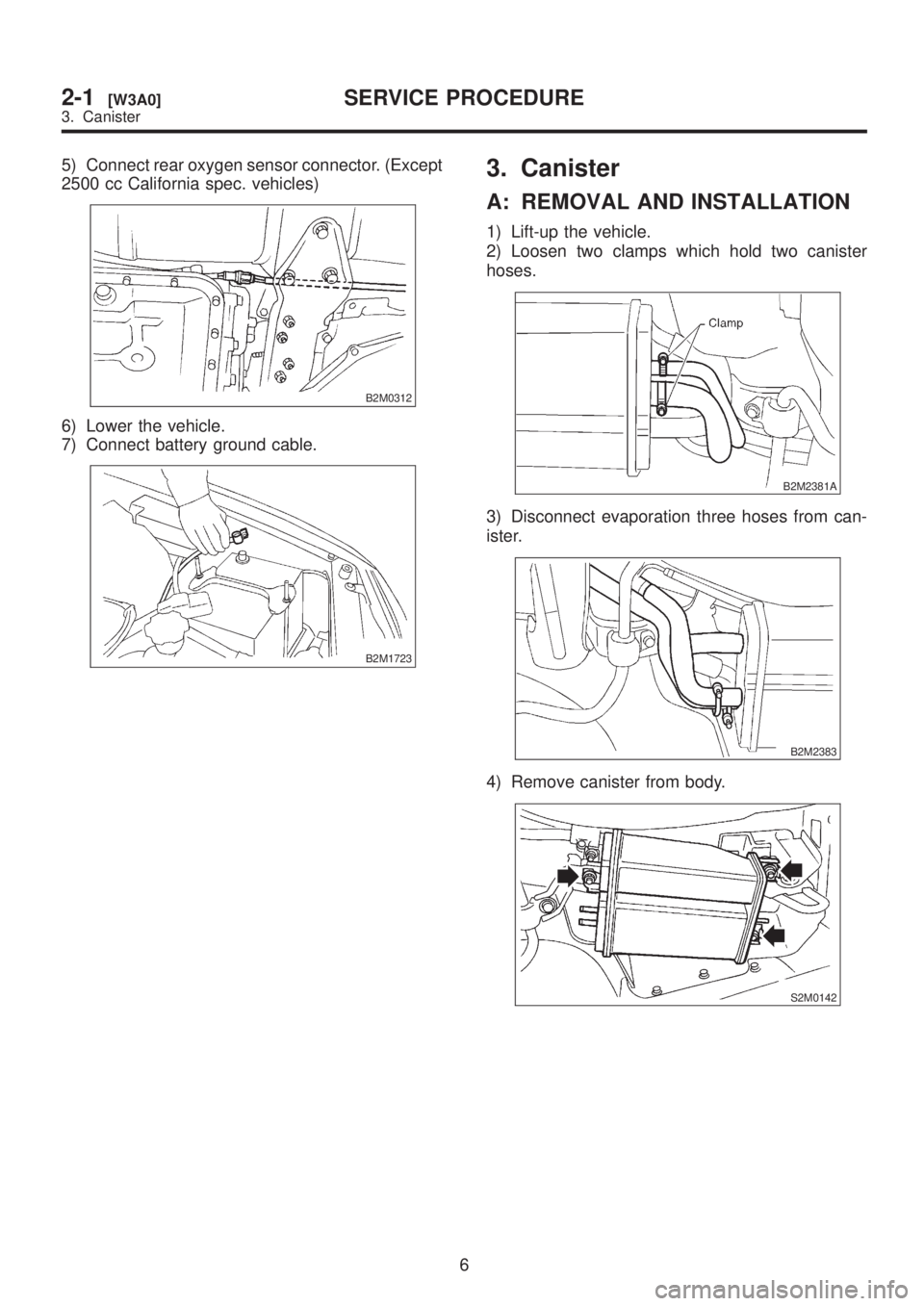
5) Connect rear oxygen sensor connector. (Except
2500 cc California spec. vehicles)
B2M0312
6) Lower the vehicle.
7) Connect battery ground cable.
B2M1723
3. Canister
A: REMOVAL AND INSTALLATION
1) Lift-up the vehicle.
2) Loosen two clamps which hold two canister
hoses.
B2M2381A
3) Disconnect evaporation three hoses from can-
ister.
B2M2383
4) Remove canister from body.
S2M0142
6
2-1[W3A0]SERVICE PROCEDURE
3. Canister
Page 7 of 1456
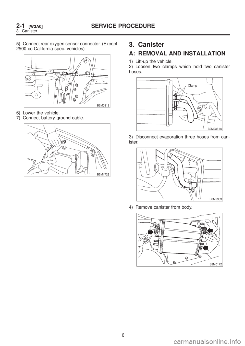
5) Connect rear oxygen sensor connector. (Except
2500 cc California spec. vehicles)
B2M0312
6) Lower the vehicle.
7) Connect battery ground cable.
B2M1723
3. Canister
A: REMOVAL AND INSTALLATION
1) Lift-up the vehicle.
2) Loosen two clamps which hold two canister
hoses.
B2M2381A
3) Disconnect evaporation three hoses from can-
ister.
B2M2383
4) Remove canister from body.
S2M0142
6
2-1[W3A0]SERVICE PROCEDURE
3. Canister
Page 35 of 1456
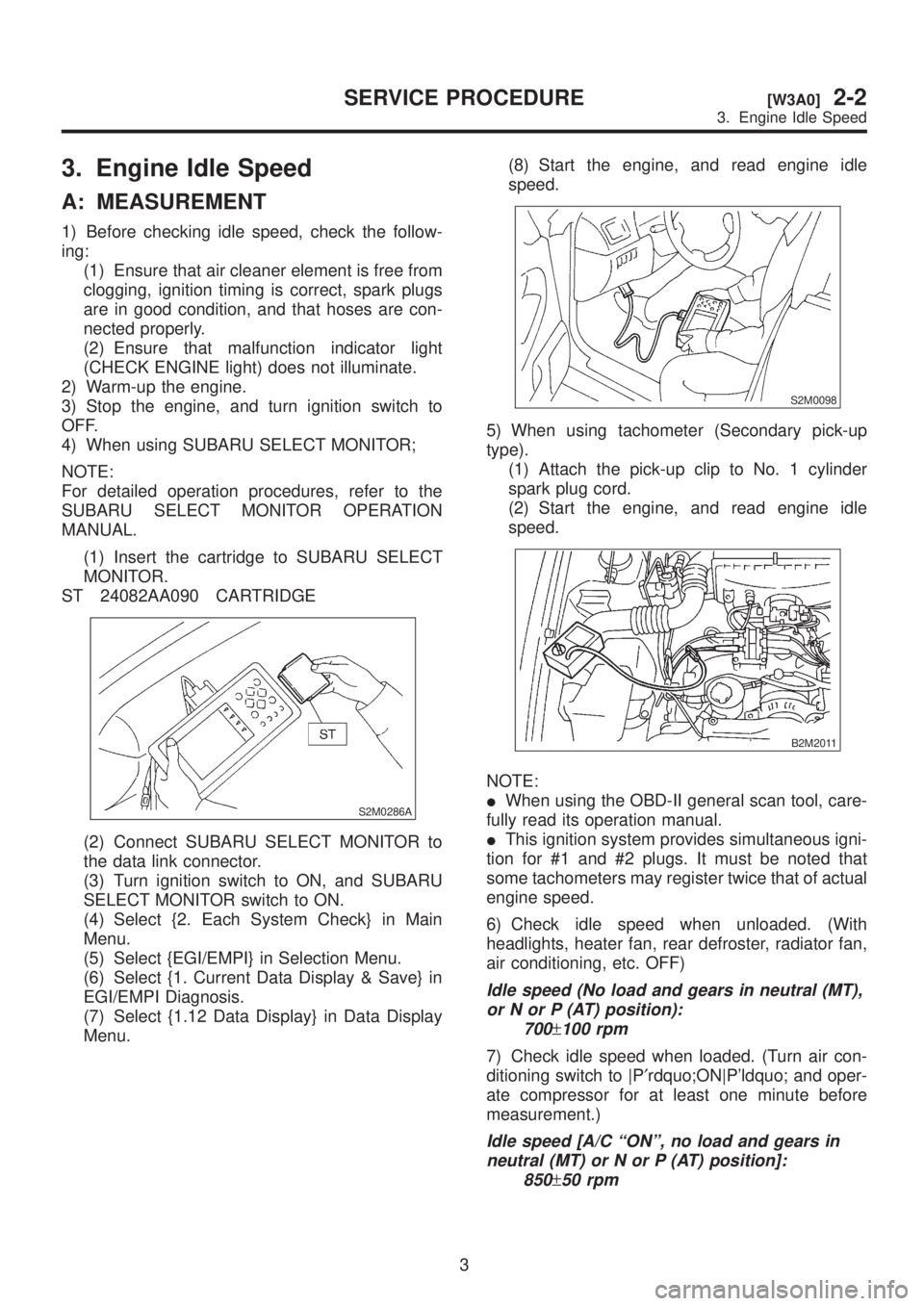
3. Engine Idle Speed
A: MEASUREMENT
1) Before checking idle speed, check the follow-
ing:
(1) Ensure that air cleaner element is free from
clogging, ignition timing is correct, spark plugs
are in good condition, and that hoses are con-
nected properly.
(2) Ensure that malfunction indicator light
(CHECK ENGINE light) does not illuminate.
2) Warm-up the engine.
3) Stop the engine, and turn ignition switch to
OFF.
4) When using SUBARU SELECT MONITOR;
NOTE:
For detailed operation procedures, refer to the
SUBARU SELECT MONITOR OPERATION
MANUAL.
(1) Insert the cartridge to SUBARU SELECT
MONITOR.
ST 24082AA090 CARTRIDGE
S2M0286A
(2) Connect SUBARU SELECT MONITOR to
the data link connector.
(3) Turn ignition switch to ON, and SUBARU
SELECT MONITOR switch to ON.
(4) Select {2. Each System Check} in Main
Menu.
(5) Select {EGI/EMPI} in Selection Menu.
(6) Select {1. Current Data Display & Save} in
EGI/EMPI Diagnosis.
(7) Select {1.12 Data Display} in Data Display
Menu.(8) Start the engine, and read engine idle
speed.
S2M0098
5) When using tachometer (Secondary pick-up
type).
(1) Attach the pick-up clip to No. 1 cylinder
spark plug cord.
(2) Start the engine, and read engine idle
speed.
B2M2011
NOTE:
IWhen using the OBD-II general scan tool, care-
fully read its operation manual.
IThis ignition system provides simultaneous igni-
tion for #1 and #2 plugs. It must be noted that
some tachometers may register twice that of actual
engine speed.
6) Check idle speed when unloaded. (With
headlights, heater fan, rear defroster, radiator fan,
air conditioning, etc. OFF)
Idle speed (No load and gears in neutral (MT),
or N or P (AT) position):
700
±100 rpm
7) Check idle speed when loaded. (Turn air con-
ditioning switch to |P¢rdquo;ON|P'ldquo; and oper-
ate compressor for at least one minute before
measurement.)
Idle speed [A/C ªONº, no load and gears in
neutral (MT) or N or P (AT) position]:
850
±50 rpm
3
[W3A0]2-2SERVICE PROCEDURE
3. Engine Idle Speed
Page 45 of 1456
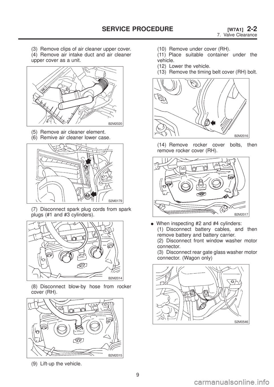
(3) Remove clips of air cleaner upper cover.
(4) Remove air intake duct and air cleaner
upper cover as a unit.
B2M2020
(5) Remove air cleaner element.
(6) Remive air cleaner lower case.
S2M0179
(7) Disconnect spark plug cords from spark
plugs (#1 and #3 cylinders).
B2M2014
(8) Disconnect blow-by hose from rocker
cover (RH).
B2M2015
(9) Lift-up the vehicle.(10) Remove under cover (RH).
(11) Place suitable container under the
vehicle.
(12) Lower the vehicle.
(13) Remove the timing belt cover (RH) bolt.
B2M2016
(14) Remove rocker cover bolts, then
remove rocker cover (RH).
B2M2017
IWhen inspecting #2 and #4 cylinders:
(1) Disconnect battery cables, and then
remove battery and battery carrier.
(2) Disconnect front window washer motor
connector.
(3) Disconnect rear gate glass washer motor
connector. (Wagon only)
S2M0546
9
[W7A1]2-2SERVICE PROCEDURE
7. Valve Clearance
Page 46 of 1456
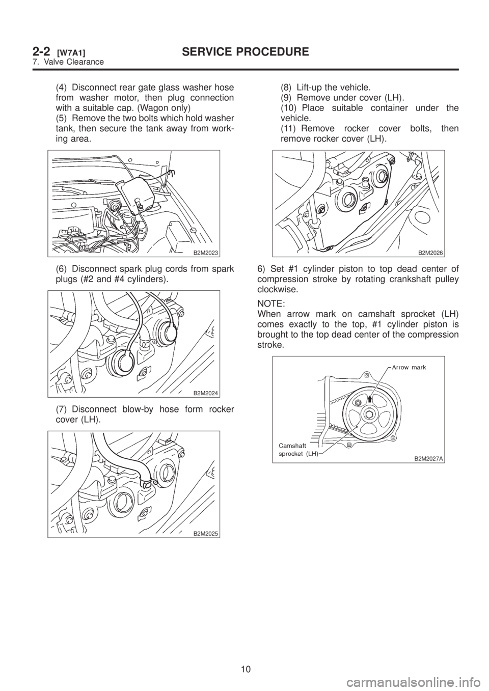
(4) Disconnect rear gate glass washer hose
from washer motor, then plug connection
with a suitable cap. (Wagon only)
(5) Remove the two bolts which hold washer
tank, then secure the tank away from work-
ing area.
B2M2023
(6) Disconnect spark plug cords from spark
plugs (#2 and #4 cylinders).
B2M2024
(7) Disconnect blow-by hose form rocker
cover (LH).
B2M2025
(8) Lift-up the vehicle.
(9) Remove under cover (LH).
(10) Place suitable container under the
vehicle.
(11) Remove rocker cover bolts, then
remove rocker cover (LH).
B2M2026
6) Set #1 cylinder piston to top dead center of
compression stroke by rotating crankshaft pulley
clockwise.
NOTE:
When arrow mark on camshaft sprocket (LH)
comes exactly to the top, #1 cylinder piston is
brought to the top dead center of the compression
stroke.
B2M2027A
10
2-2[W7A1]SERVICE PROCEDURE
7. Valve Clearance