spark plugs SUBARU LEGACY 1999 Service Repair Manual
[x] Cancel search | Manufacturer: SUBARU, Model Year: 1999, Model line: LEGACY, Model: SUBARU LEGACY 1999Pages: 1456, PDF Size: 59.93 MB
Page 35 of 1456
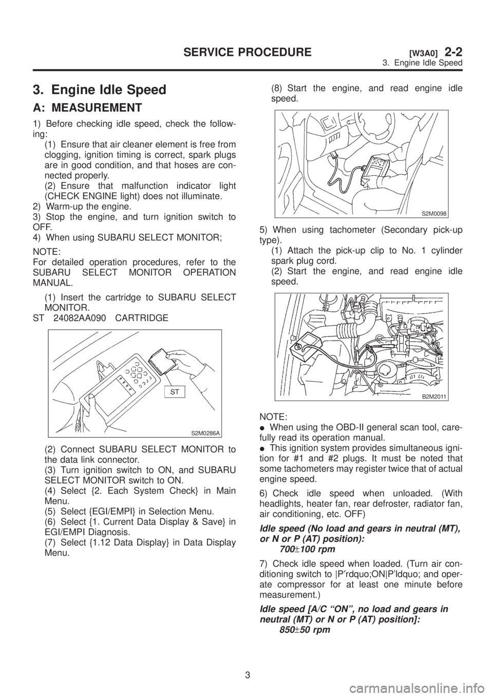
3. Engine Idle Speed
A: MEASUREMENT
1) Before checking idle speed, check the follow-
ing:
(1) Ensure that air cleaner element is free from
clogging, ignition timing is correct, spark plugs
are in good condition, and that hoses are con-
nected properly.
(2) Ensure that malfunction indicator light
(CHECK ENGINE light) does not illuminate.
2) Warm-up the engine.
3) Stop the engine, and turn ignition switch to
OFF.
4) When using SUBARU SELECT MONITOR;
NOTE:
For detailed operation procedures, refer to the
SUBARU SELECT MONITOR OPERATION
MANUAL.
(1) Insert the cartridge to SUBARU SELECT
MONITOR.
ST 24082AA090 CARTRIDGE
S2M0286A
(2) Connect SUBARU SELECT MONITOR to
the data link connector.
(3) Turn ignition switch to ON, and SUBARU
SELECT MONITOR switch to ON.
(4) Select {2. Each System Check} in Main
Menu.
(5) Select {EGI/EMPI} in Selection Menu.
(6) Select {1. Current Data Display & Save} in
EGI/EMPI Diagnosis.
(7) Select {1.12 Data Display} in Data Display
Menu.(8) Start the engine, and read engine idle
speed.
S2M0098
5) When using tachometer (Secondary pick-up
type).
(1) Attach the pick-up clip to No. 1 cylinder
spark plug cord.
(2) Start the engine, and read engine idle
speed.
B2M2011
NOTE:
IWhen using the OBD-II general scan tool, care-
fully read its operation manual.
IThis ignition system provides simultaneous igni-
tion for #1 and #2 plugs. It must be noted that
some tachometers may register twice that of actual
engine speed.
6) Check idle speed when unloaded. (With
headlights, heater fan, rear defroster, radiator fan,
air conditioning, etc. OFF)
Idle speed (No load and gears in neutral (MT),
or N or P (AT) position):
700
±100 rpm
7) Check idle speed when loaded. (Turn air con-
ditioning switch to |P¢rdquo;ON|P'ldquo; and oper-
ate compressor for at least one minute before
measurement.)
Idle speed [A/C ªONº, no load and gears in
neutral (MT) or N or P (AT) position]:
850
±50 rpm
3
[W3A0]2-2SERVICE PROCEDURE
3. Engine Idle Speed
Page 36 of 1456
![SUBARU LEGACY 1999 Service Repair Manual CAUTION:
Never rotate idle adjusting screw. If idle speed
is out of specifications, refer to General On-
board Diagnosis Table under ª2-7 On-Board
Diagnostics II Systemº.
<Ref. to 2-7 [T6A0].>4. Eng SUBARU LEGACY 1999 Service Repair Manual CAUTION:
Never rotate idle adjusting screw. If idle speed
is out of specifications, refer to General On-
board Diagnosis Table under ª2-7 On-Board
Diagnostics II Systemº.
<Ref. to 2-7 [T6A0].>4. Eng](/img/17/57435/w960_57435-35.png)
CAUTION:
Never rotate idle adjusting screw. If idle speed
is out of specifications, refer to General On-
board Diagnosis Table under ª2-7 On-Board
Diagnostics II Systemº.
A: MEASUREMENT
1. 2200 cc MODEL
1) After warming-up the engine, turn ignition
switch to OFF.
2) Make sure that the battery is fully charged.
3) Remove all the spark plugs.
4) Disconnect connectors from fuel injectors.
5) Fully open throttle valve.
6) Check the starter motor for satisfactory perfor-
mance and operation.
7) Hold the compression gauge tight against the
spark plug hole.
CAUTION:
When using a screw-in type compression
gauge, the screw (put into cylinder head spark
plug hole) should be less than 18 mm (0.71 in)
long.
8) Crank the engine by means of the starter motor,
and read the maximum value on the gauge when
the pointer is steady.
G2M0098
9) Perform at least two measurements per
cylinder, and make sure that the values are correct.
Compression (200 Ð 300 rpm and fully open
throttle):
Standard;
1,079 Ð 1,275 kPa (11.0 Ð 13.0 kg/cm
2,
156 Ð 185 psi)
Limit;
883 kPa (9.0 kg/cm
2, 128 psi)
Difference between cylinders;
196 kPa (2.0 kg/cm
2, 28 psi)
4
2-2[W4A1]SERVICE PROCEDURE
4. Engine Compression
Page 37 of 1456
![SUBARU LEGACY 1999 Service Repair Manual CAUTION:
Never rotate idle adjusting screw. If idle speed
is out of specifications, refer to General On-
board Diagnosis Table under ª2-7 On-Board
Diagnostics II Systemº.
<Ref. to 2-7 [T6A0].>4. Eng SUBARU LEGACY 1999 Service Repair Manual CAUTION:
Never rotate idle adjusting screw. If idle speed
is out of specifications, refer to General On-
board Diagnosis Table under ª2-7 On-Board
Diagnostics II Systemº.
<Ref. to 2-7 [T6A0].>4. Eng](/img/17/57435/w960_57435-36.png)
CAUTION:
Never rotate idle adjusting screw. If idle speed
is out of specifications, refer to General On-
board Diagnosis Table under ª2-7 On-Board
Diagnostics II Systemº.
A: MEASUREMENT
1. 2200 cc MODEL
1) After warming-up the engine, turn ignition
switch to OFF.
2) Make sure that the battery is fully charged.
3) Remove all the spark plugs.
4) Disconnect connectors from fuel injectors.
5) Fully open throttle valve.
6) Check the starter motor for satisfactory perfor-
mance and operation.
7) Hold the compression gauge tight against the
spark plug hole.
CAUTION:
When using a screw-in type compression
gauge, the screw (put into cylinder head spark
plug hole) should be less than 18 mm (0.71 in)
long.
8) Crank the engine by means of the starter motor,
and read the maximum value on the gauge when
the pointer is steady.
G2M0098
9) Perform at least two measurements per
cylinder, and make sure that the values are correct.
Compression (200 Ð 300 rpm and fully open
throttle):
Standard;
1,079 Ð 1,275 kPa (11.0 Ð 13.0 kg/cm
2,
156 Ð 185 psi)
Limit;
883 kPa (9.0 kg/cm
2, 128 psi)
Difference between cylinders;
196 kPa (2.0 kg/cm
2, 28 psi)
4
2-2[W4A1]SERVICE PROCEDURE
4. Engine Compression
Page 38 of 1456
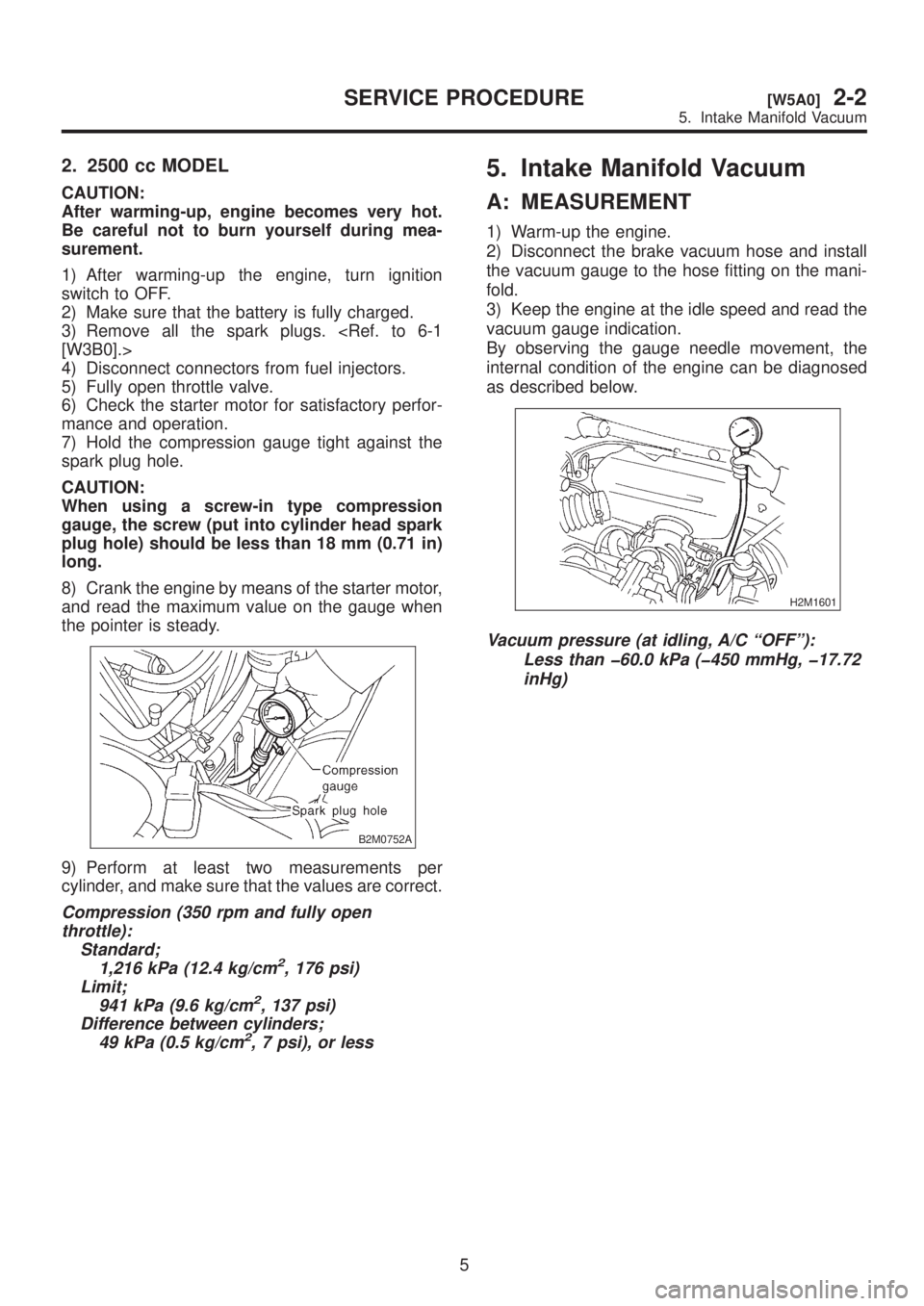
2. 2500 cc MODEL
CAUTION:
After warming-up, engine becomes very hot.
Be careful not to burn yourself during mea-
surement.
1) After warming-up the engine, turn ignition
switch to OFF.
2) Make sure that the battery is fully charged.
3) Remove all the spark plugs.
4) Disconnect connectors from fuel injectors.
5) Fully open throttle valve.
6) Check the starter motor for satisfactory perfor-
mance and operation.
7) Hold the compression gauge tight against the
spark plug hole.
CAUTION:
When using a screw-in type compression
gauge, the screw (put into cylinder head spark
plug hole) should be less than 18 mm (0.71 in)
long.
8) Crank the engine by means of the starter motor,
and read the maximum value on the gauge when
the pointer is steady.
B2M0752A
9) Perform at least two measurements per
cylinder, and make sure that the values are correct.
Compression (350 rpm and fully open
throttle):
Standard;
1,216 kPa (12.4 kg/cm
2, 176 psi)
Limit;
941 kPa (9.6 kg/cm
2, 137 psi)
Difference between cylinders;
49 kPa (0.5 kg/cm
2, 7 psi), or less
5. Intake Manifold Vacuum
A: MEASUREMENT
1) Warm-up the engine.
2) Disconnect the brake vacuum hose and install
the vacuum gauge to the hose fitting on the mani-
fold.
3) Keep the engine at the idle speed and read the
vacuum gauge indication.
By observing the gauge needle movement, the
internal condition of the engine can be diagnosed
as described below.
H2M1601
Vacuum pressure (at idling, A/C ªOFFº):
Less than þ60.0 kPa (þ450 mmHg, þ17.72
inHg)
5
[W5A0]2-2SERVICE PROCEDURE
5. Intake Manifold Vacuum
Page 39 of 1456
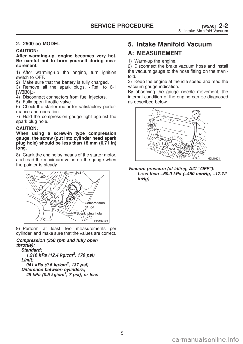
2. 2500 cc MODEL
CAUTION:
After warming-up, engine becomes very hot.
Be careful not to burn yourself during mea-
surement.
1) After warming-up the engine, turn ignition
switch to OFF.
2) Make sure that the battery is fully charged.
3) Remove all the spark plugs.
4) Disconnect connectors from fuel injectors.
5) Fully open throttle valve.
6) Check the starter motor for satisfactory perfor-
mance and operation.
7) Hold the compression gauge tight against the
spark plug hole.
CAUTION:
When using a screw-in type compression
gauge, the screw (put into cylinder head spark
plug hole) should be less than 18 mm (0.71 in)
long.
8) Crank the engine by means of the starter motor,
and read the maximum value on the gauge when
the pointer is steady.
B2M0752A
9) Perform at least two measurements per
cylinder, and make sure that the values are correct.
Compression (350 rpm and fully open
throttle):
Standard;
1,216 kPa (12.4 kg/cm
2, 176 psi)
Limit;
941 kPa (9.6 kg/cm
2, 137 psi)
Difference between cylinders;
49 kPa (0.5 kg/cm
2, 7 psi), or less
5. Intake Manifold Vacuum
A: MEASUREMENT
1) Warm-up the engine.
2) Disconnect the brake vacuum hose and install
the vacuum gauge to the hose fitting on the mani-
fold.
3) Keep the engine at the idle speed and read the
vacuum gauge indication.
By observing the gauge needle movement, the
internal condition of the engine can be diagnosed
as described below.
H2M1601
Vacuum pressure (at idling, A/C ªOFFº):
Less than þ60.0 kPa (þ450 mmHg, þ17.72
inHg)
5
[W5A0]2-2SERVICE PROCEDURE
5. Intake Manifold Vacuum
Page 44 of 1456
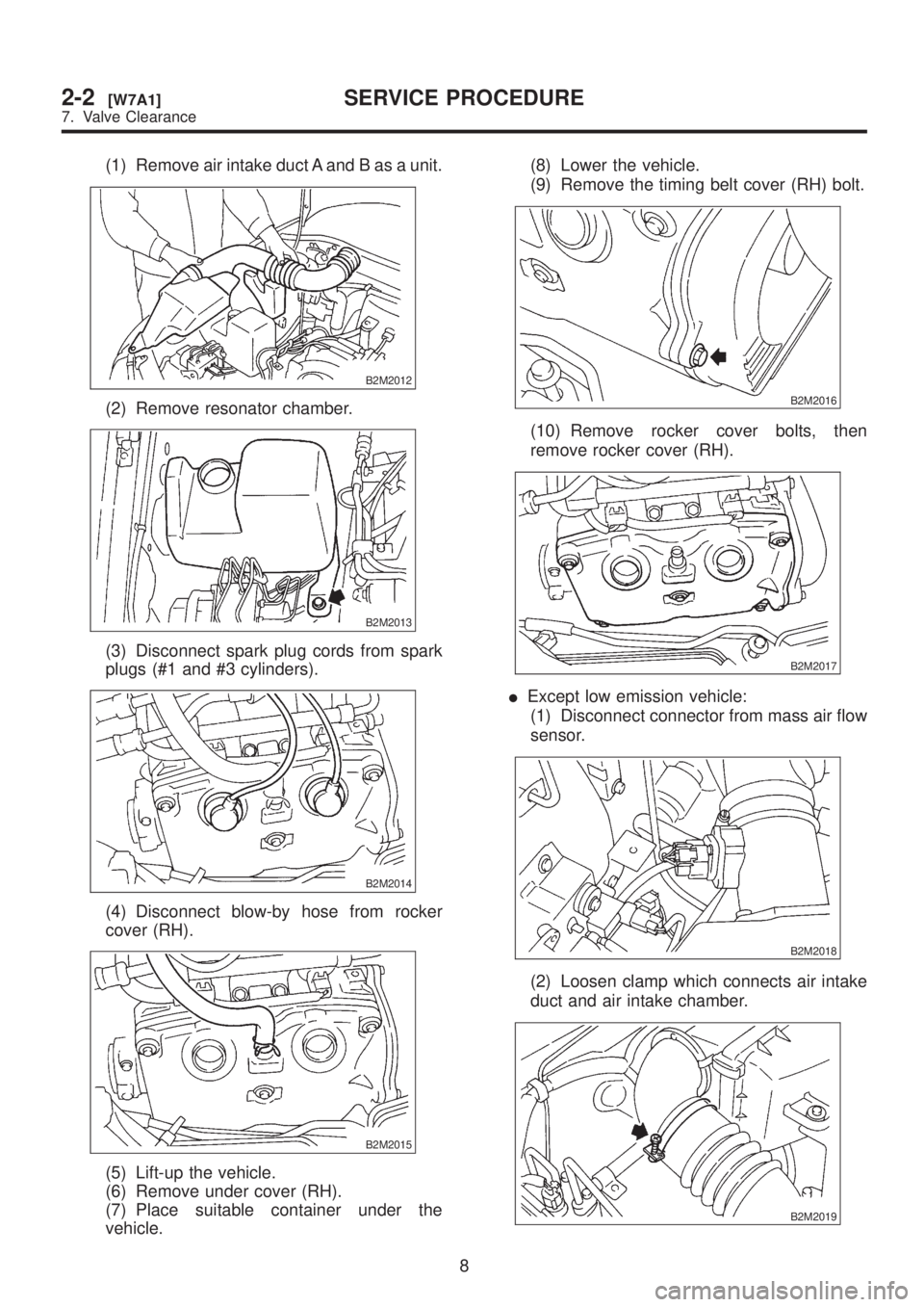
(1) Remove air intake duct A and B as a unit.
B2M2012
(2) Remove resonator chamber.
B2M2013
(3) Disconnect spark plug cords from spark
plugs (#1 and #3 cylinders).
B2M2014
(4) Disconnect blow-by hose from rocker
cover (RH).
B2M2015
(5) Lift-up the vehicle.
(6) Remove under cover (RH).
(7) Place suitable container under the
vehicle.(8) Lower the vehicle.
(9) Remove the timing belt cover (RH) bolt.
B2M2016
(10) Remove rocker cover bolts, then
remove rocker cover (RH).
B2M2017
IExcept low emission vehicle:
(1) Disconnect connector from mass air flow
sensor.
B2M2018
(2) Loosen clamp which connects air intake
duct and air intake chamber.
B2M2019
8
2-2[W7A1]SERVICE PROCEDURE
7. Valve Clearance
Page 45 of 1456
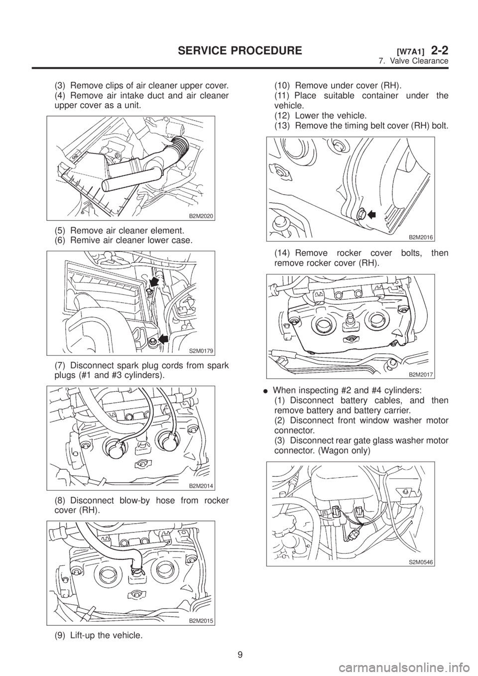
(3) Remove clips of air cleaner upper cover.
(4) Remove air intake duct and air cleaner
upper cover as a unit.
B2M2020
(5) Remove air cleaner element.
(6) Remive air cleaner lower case.
S2M0179
(7) Disconnect spark plug cords from spark
plugs (#1 and #3 cylinders).
B2M2014
(8) Disconnect blow-by hose from rocker
cover (RH).
B2M2015
(9) Lift-up the vehicle.(10) Remove under cover (RH).
(11) Place suitable container under the
vehicle.
(12) Lower the vehicle.
(13) Remove the timing belt cover (RH) bolt.
B2M2016
(14) Remove rocker cover bolts, then
remove rocker cover (RH).
B2M2017
IWhen inspecting #2 and #4 cylinders:
(1) Disconnect battery cables, and then
remove battery and battery carrier.
(2) Disconnect front window washer motor
connector.
(3) Disconnect rear gate glass washer motor
connector. (Wagon only)
S2M0546
9
[W7A1]2-2SERVICE PROCEDURE
7. Valve Clearance
Page 46 of 1456
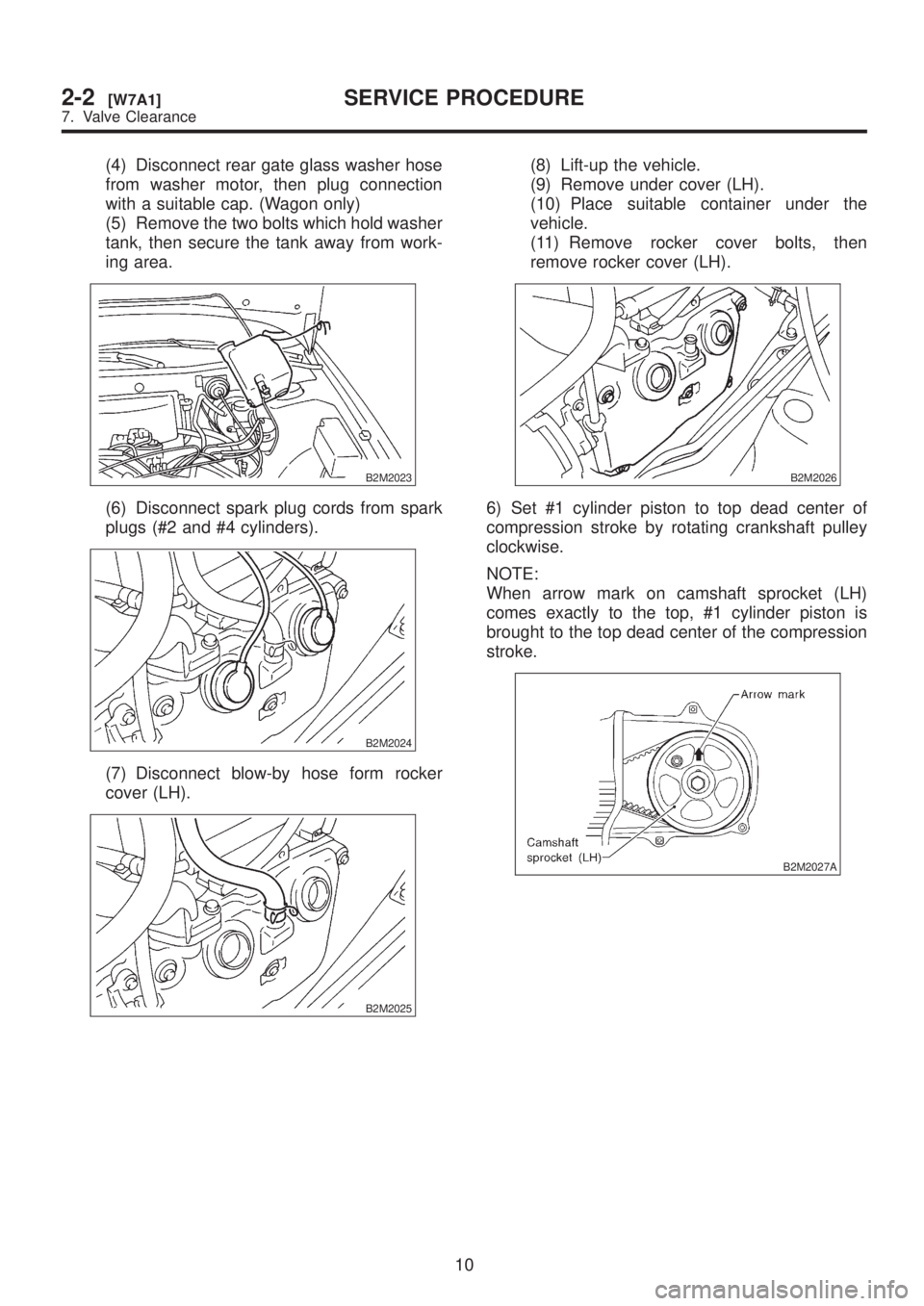
(4) Disconnect rear gate glass washer hose
from washer motor, then plug connection
with a suitable cap. (Wagon only)
(5) Remove the two bolts which hold washer
tank, then secure the tank away from work-
ing area.
B2M2023
(6) Disconnect spark plug cords from spark
plugs (#2 and #4 cylinders).
B2M2024
(7) Disconnect blow-by hose form rocker
cover (LH).
B2M2025
(8) Lift-up the vehicle.
(9) Remove under cover (LH).
(10) Place suitable container under the
vehicle.
(11) Remove rocker cover bolts, then
remove rocker cover (LH).
B2M2026
6) Set #1 cylinder piston to top dead center of
compression stroke by rotating crankshaft pulley
clockwise.
NOTE:
When arrow mark on camshaft sprocket (LH)
comes exactly to the top, #1 cylinder piston is
brought to the top dead center of the compression
stroke.
B2M2027A
10
2-2[W7A1]SERVICE PROCEDURE
7. Valve Clearance
Page 48 of 1456
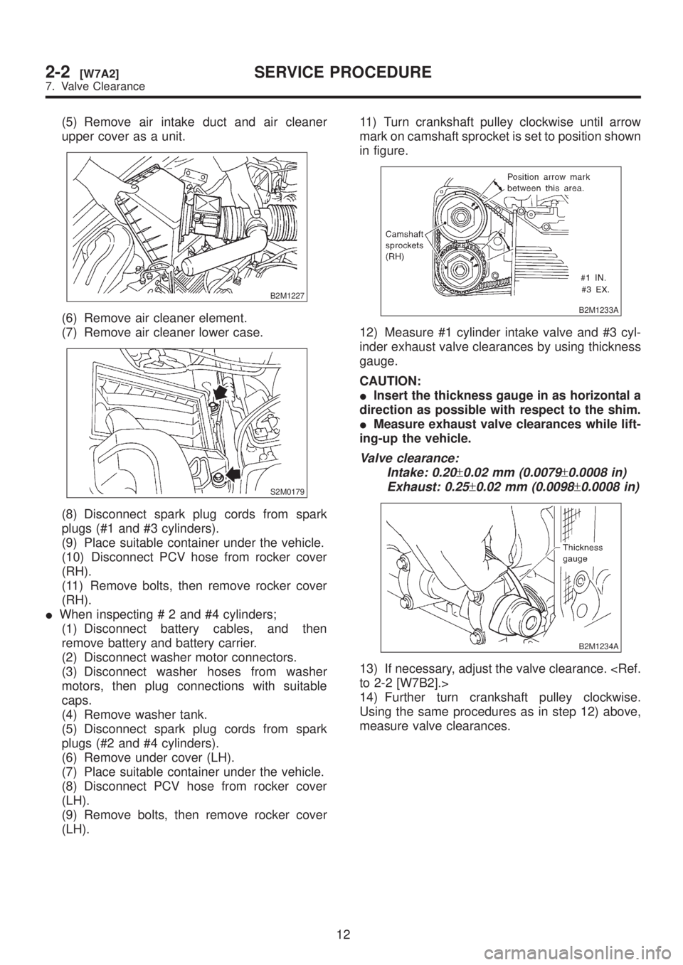
(5) Remove air intake duct and air cleaner
upper cover as a unit.
B2M1227
(6) Remove air cleaner element.
(7) Remove air cleaner lower case.
S2M0179
(8) Disconnect spark plug cords from spark
plugs (#1 and #3 cylinders).
(9) Place suitable container under the vehicle.
(10) Disconnect PCV hose from rocker cover
(RH).
(11) Remove bolts, then remove rocker cover
(RH).
IWhen inspecting # 2 and #4 cylinders;
(1) Disconnect battery cables, and then
remove battery and battery carrier.
(2) Disconnect washer motor connectors.
(3) Disconnect washer hoses from washer
motors, then plug connections with suitable
caps.
(4) Remove washer tank.
(5) Disconnect spark plug cords from spark
plugs (#2 and #4 cylinders).
(6) Remove under cover (LH).
(7) Place suitable container under the vehicle.
(8) Disconnect PCV hose from rocker cover
(LH).
(9) Remove bolts, then remove rocker cover
(LH).11) Turn crankshaft pulley clockwise until arrow
mark on camshaft sprocket is set to position shown
in figure.
B2M1233A
12) Measure #1 cylinder intake valve and #3 cyl-
inder exhaust valve clearances by using thickness
gauge.
CAUTION:
IInsert the thickness gauge in as horizontal a
direction as possible with respect to the shim.
IMeasure exhaust valve clearances while lift-
ing-up the vehicle.
Valve clearance:
Intake: 0.20
±0.02 mm (0.0079±0.0008 in)
Exhaust: 0.25
±0.02 mm (0.0098±0.0008 in)
B2M1234A
13) If necessary, adjust the valve clearance.
14) Further turn crankshaft pulley clockwise.
Using the same procedures as in step 12) above,
measure valve clearances.
12
2-2[W7A2]SERVICE PROCEDURE
7. Valve Clearance
Page 127 of 1456
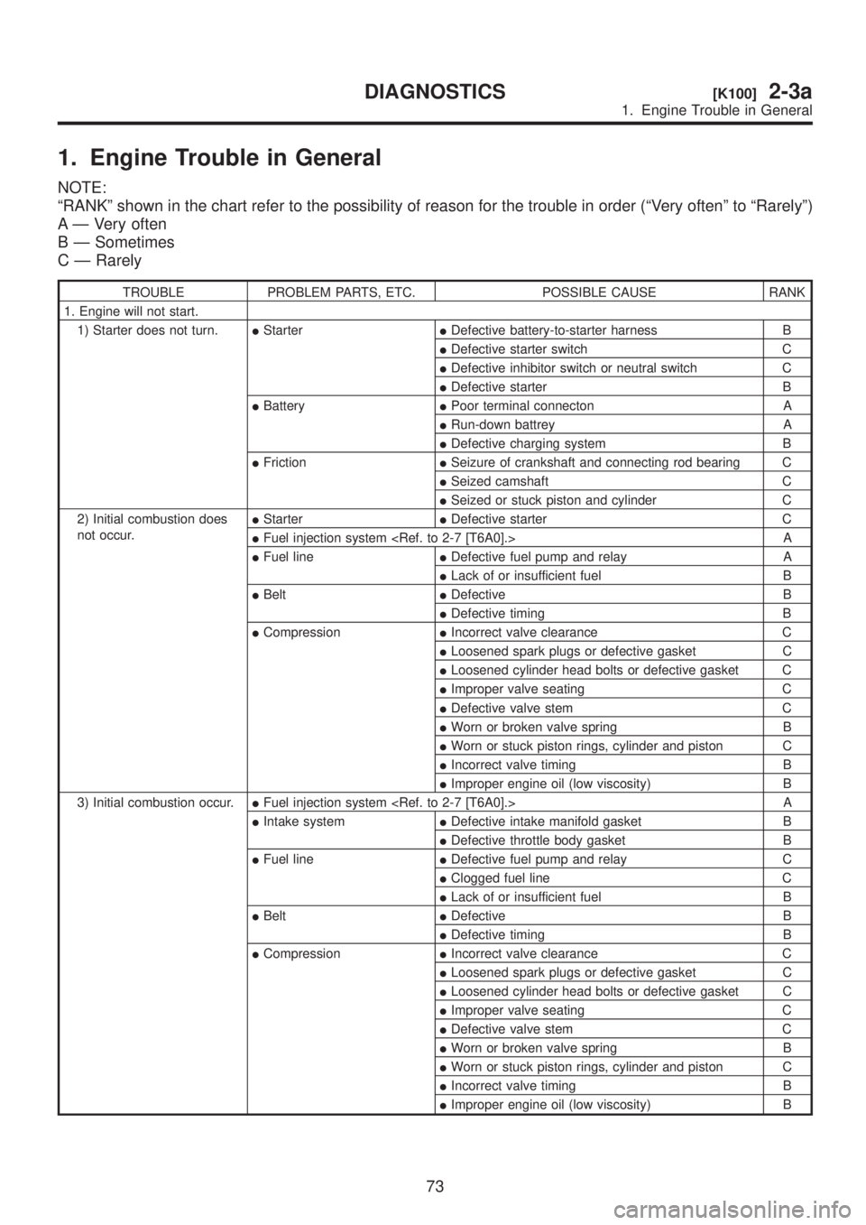
1. Engine Trouble in General
NOTE:
ªRANKº shown in the chart refer to the possibility of reason for the trouble in order (ªVery oftenº to ªRarelyº)
A Ð Very often
B Ð Sometimes
C Ð Rarely
TROUBLE PROBLEM PARTS, ETC. POSSIBLE CAUSE RANK
1. Engine will not start.
1) Starter does not turn.IStarterIDefective battery-to-starter harness B
IDefective starter switch C
IDefective inhibitor switch or neutral switch C
IDefective starter B
IBatteryIPoor terminal connecton A
IRun-down battrey A
IDefective charging system B
IFrictionISeizure of crankshaft and connecting rod bearing C
ISeized camshaft C
ISeized or stuck piston and cylinder C
2) Initial combustion does
not occur.IStarterIDefective starter C
IFuel injection system
IFuel lineIDefective fuel pump and relay A
ILack of or insufficient fuel B
IBeltIDefective B
IDefective timing B
ICompressionIIncorrect valve clearance C
ILoosened spark plugs or defective gasket C
ILoosened cylinder head bolts or defective gasket C
IImproper valve seating C
IDefective valve stem C
IWorn or broken valve spring B
IWorn or stuck piston rings, cylinder and piston C
IIncorrect valve timing B
IImproper engine oil (low viscosity) B
3) Initial combustion occur.IFuel injection system
IIntake systemIDefective intake manifold gasket B
IDefective throttle body gasket B
IFuel lineIDefective fuel pump and relay C
IClogged fuel line C
ILack of or insufficient fuel B
IBeltIDefective B
IDefective timing B
ICompressionIIncorrect valve clearance C
ILoosened spark plugs or defective gasket C
ILoosened cylinder head bolts or defective gasket C
IImproper valve seating C
IDefective valve stem C
IWorn or broken valve spring B
IWorn or stuck piston rings, cylinder and piston C
IIncorrect valve timing B
IImproper engine oil (low viscosity) B
73
[K100]2-3aDIAGNOSTICS
1. Engine Trouble in General