cvt SUBARU LEGACY 2012 5.G Owners Manual
[x] Cancel search | Manufacturer: SUBARU, Model Year: 2012, Model line: LEGACY, Model: SUBARU LEGACY 2012 5.GPages: 474, PDF Size: 17.45 MB
Page 5 of 474

2
Chapter 12: Specifications
This chapter informs you about the dimen-
sions and capacities of your SUBARU.
Chapter 13: Consumer information and
Reporting safety defects
This chapter informs you about Tire
information, Uniform tire quality grading
standards and Reporting safety defects.
Chapter 14: Index
This is an alphabetical listing of all that’sin
this manual. You can use it to quickly find
something you want to read. & Safety warnings
You will find a number of WARNINGs,
CAUTIONs and NOTEs in this manual.
These safety warnings alert you to poten-
tial hazards that could result in injury to
you or others.
Please read these safety warnings as well
as all other portions of this manual care-
fully in order to gain a better understand-
ing of how to use your SUBARU vehicle
safely.
WARNING
A WARNING indicates a situation in
which serious injury or death could
result if the warning is ignored.
CAUTION
A CAUTION indicates a situation in
which injury or damage to your
vehicle, or both, could result if the
caution is ignored.
NOTE
A NOTE gives information or sugges-
tions how to make better use of yourvehicle. & Safety symbol
You will find a circle with a slash through it
in this manual. This symbol means “Do
not ”, “Do not do this ”,or “Do not let this
happen ”, depending upon the context. &
Abbreviation list
You will find several abbreviations in this
manual. The meanings of the abbrevia-
tions are shown in the following list.
Abbreviation Meaning
A/C Air conditioner A/ELR Automatic/Emergency locking retractor
ABS Anti-lock brake system
AKI Anti knock index
ALR Automatic locking retractor
AT Automatic transmission
ATF Automatic transmission fluid
AWD All-wheel drive CVT Continuously variable trans- mission
DRL Daytime running light EBD Electronic brake force distri- bution
ELR Emergency locking retractor
FWD Front-wheel drive
GAW Gross axle weight
GAWR Gross axle weight rating
GPS Global positioning system
GVW Gross vehicle weight
GVWR Gross vehicle weight rating
Page 17 of 474

14
1) Shift lever (MT) (page 7-15)/Select lever(AT and CVT) (page 7-18)
2) Climate control (page 4-1)
3) Audio (page 5-1)
4) Navigation system (Refer to the Owner ’s
Manual supplement for the navigation system)
5) Multi function display (page 3-24)
6) Glove box (page 6-6)
7) Cup holder (page 6-8)
Page 22 of 474

&Warning and indicator lights
Mark Name Page
Seatbelt warning light 3-9
Front passenger ’s
seatbelt warning light 3-9
SRS airbag system
warning light3-11
CHECK ENGINE warn-
ing light/Malfunction in-
dicator light3-12
Coolant temperature
low indicator light/Cool-
ant temperature high
warning light3-13
Charge warning light 3-14
Oil pressure warning light
3-14
Engine oil level warning light3-14
AT OIL TEMP warning
light (AT and CVT mod- els)3-14
/ABS warning light 3-16 Mark Name Page
/Brake system warning light
3-17
Hill Holder indicator light3-19
Door open indicator light
3-19
Low fuel warning light 3-19
All-Wheel Drive warn-
ing light (AT and CVT models)3-20
Vehicle Dynamics Con-
trol warning light/Vehi-
cle Dynamics Control
operation indicator light3-20
Vehicle Dynamics Con-
trol OFF indicator light
3-21
Security indicator light 3-21
Turn signal indicator lights
3-22
High beam indicator light3-22
Front fog light indicator
light (if equipped)3-23Mark Name Page
Cruise control indicator light
3-23
Cruise control set indi-
cator light3-23
Headlight indicator light 3-23
Low tire pressure
warning light
(U.S. spec. models)3-15
/Front passenger
’s fron-
tal airbag ON indicator light 3-11
/Front passenger
’s fron-
tal airbag OFF indicator light 3-11
Shift-up indicator 3-22
Windshield washer fluid
warning light
3-1919
Page 120 of 474

Ignition switch..................................................... 3-3
LOCK .................................................................. 3-3
Acc..................................................................... 3-4
ON...................................................................... 3-4
START ................................................................ 3-4
Key reminder chime ............................................ 3-4
Ignition switch light ............................................. 3-4
Hazard warning flasher ....................................... 3-5
Meters and gauges. ............................................. 3-5
Combination meter illumination ........................... 3-5
Canceling the function for meter/gauge needle movement upon turning on the ignition switch ............................................................... 3-5
Speedometer ....................................................... 3-6
Odometer ............................................................ 3-6
Double trip meter ................................................ 3-6
Tachometer ......................................................... 3-7
Fuel gauge .......................................................... 3-7
ECO gauge ......................................................... 3-8
Warning and indicator lights .............................. 3-9
Seatbelt warning light and chime ......................... 3-9
SRS airbag system warning light ........................ 3-11
Front passenger ’s frontal airbag ON and OFF
indicators ......................................................... 3-11
CHECK ENGINE warning light/Malfunction indicator light ................................................... 3-12
Coolant temperature low indicator light/Coolant temperature high warning light ......................... 3-13
Charge warning light .......................................... 3-14
Oil pressure warning light .................................. 3-14
Engine low oil level warning light ....................... 3-14AT OIL TEMP warning light (AT and CVT
models) ........................................................... 3-14
Low tire pressure warning light (U.S. spec. models) ........................................................... 3-15
ABS warning light .............................................. 3-16
Brake system warning light ................................ 3-17
Hill Holder indicator light ................................... 3-19
Low fuel warning light ....................................... 3-19
Door open indicator light ................................... 3-19
Windshield washer fluid warning light ................ 3-19
All-Wheel Drive warning light (AT and CVT models) ........................................................... 3-20
Vehicle Dynamics Control warning light/Vehicle Dynamics Control operation indicator light .. ..... 3-20
Vehicle Dynamics Control OFF indicator light ..... 3-21
Security indicator light ....................................... 3-21
Select lever/gear position indicator ..................... 3-22
Turn signal indicator lights ................................. 3-22
High beam indicator light ................................... 3-22
Cruise control indicator light .............................. 3-23
Cruise control set indicator light ........................ 3-23
Headlight indicator light ..................................... 3-23
Front fog light indicator light (if equipped) ..... ..... 3-23
Clock .................................................................. 3-23
Multi function display ........................................ 3-24
Outside temperature indicator .. .......................... 3-24
Average fuel consumption ................................. 3-25
Current fuel consumption .................................. 3-26
Driving range on remaining fuel ......................... 3-26
Light control switch ........................................... 3-27
Headlights ......................................................... 3-27
Instruments and controls
3
Page 122 of 474

Ignition switch
WARNING
. Never turn the ignition switch to
“ LOCK ”while the vehicle is
being driven or towed because
that will lock the steering wheel,
preventing steering control. And
when the engine is turned off, it
takes a much greater effort than
usual to steer.
. Before leaving the vehicle, al-
ways remove the key from the
ignition switch for safety and
never allow an unattended child
to remain in the vehicle. Failure
to follow this procedure could
result in injury to a child or
others. Children could operate
the power windows, the moon-
roof or other controls or even
make the vehicle move.
CAUTION
Do not attach a large key holder or
key case to either key. If it banged
against your knees or hands while
you are driving, it could turn the
ignition switch from the “ON ”posi- tion to the
“Acc ”or “LOCK ”posi-
tion, thereby stopping the engine.
Also, if the key is attached to a
keyholder or to a large bunch of
other keys, centrifugal force may act
on it as the vehicle moves, resulting
in unwanted turning of the ignitionswitch.
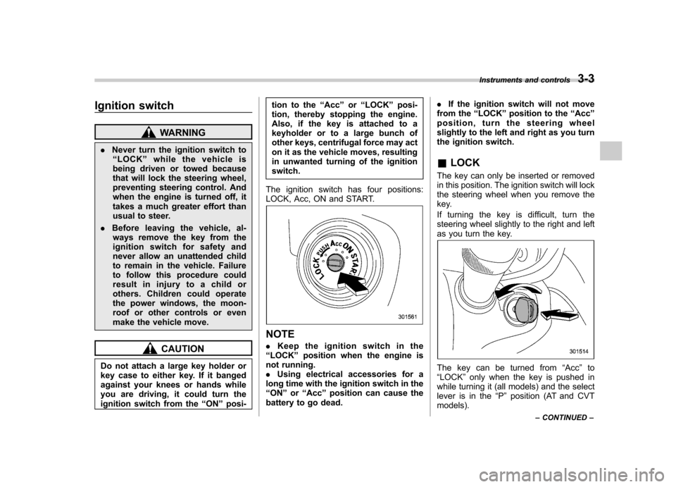
The ignition switch has four positions:
LOCK, Acc, ON and START.
NOTE . Keep the ignition switch in the
“ LOCK ”position when the engine is
not running. . Using electrical accessories for a
long time with the ignition switch in the“ ON ”or “Acc ”position can cause the
battery to go dead. .
If the ignition switch will not move
from the “LOCK ”position to the “Acc ”
position, turn the steering wheel
slightly to the left and right as you turn
the ignition switch. & LOCK
The key can only be inserted or removed
in this position. The ignition switch will lock
the steering wheel when you remove the
key.
If turning the key is difficult, turn the
steering wheel slightly to the right and left
as you turn the key.
The key can be turned from “Acc ”to
“ LOCK ”only when the key is pushed in
while turning it (all models) and the select
lever is in the “P ” position (AT and CVT
models). Instruments and controls
3-3
– CONTINUED –
Page 126 of 474

possible to switch between the A trip
meter and B trip meter indications while
the odometer/trip meter is lit up. If you do
not press the trip knob within 10 seconds
of illumination of the odometer/trip meter,
the odometer/trip meter will turn off.
Also, if you open and close the driver’s
door within 10 seconds of illumination of
the odometer/trip meter, the odometer/trip
meter will turn off.
The display can be switched as shown in
the following illustration by pressing the
trip knob.
*1: “” or “”and “”or “”cannot
be displayed when the ignition switch is
in the “ON ”position.
*
2: MT models only
To set the trip meter to zero, select the A
trip or B trip meter by pressing the knob
and keep the knob pressed for more than
2 seconds.
CAUTION
To ensure safety, do not attempt to
change the function of the indicator
during driving, as an accident couldresult.
NOTE
If the connection between the combina-
tion meter and battery is broken for any
reason such as vehicle maintenance or
fuse replacement, the data recorded on
the trip meter will be lost. & Tachometer
The tachometer shows the engine speed
in thousands of revolutions per minute.
CAUTION
Do not operate the engine with the
pointer of the tachometer in the red
zone. In this range, fuel injection will
be cut by the engine control module
to protect the engine from overrev-
ving. The engine will resume run-
ning normally after the engine speed
is reduced below the red zone. NOTE
To protect the engine while the select
lever is in the
“P ” or “N ” position (for
AT and CVT models) or the shift lever is
in the neutral position (for MT models),
the engine is controlled so that the
engine speed may not become too high
even if the accelerator pedal is pressedhard.
& Fuel gauge
1) Low fuel warning light
The fuel gauge shows the approximate
amount of fuel remaining in the tank.
When the ignition switch is in the “LOCK ”
or “Acc ”position, the fuel gauge shows “E ”
even if the fuel tank contains fuel. Instruments and controls
3-7
– CONTINUED –
Page 128 of 474

Warning and indicator lights
Several of the warning and indicator lights
illuminate momentarily and then go out
when the ignition switch is initially turned
to the“ON ”position. This permits check-
ing the operation of the bulbs.
Apply the parking brake and turn the
ignition switch to the “ON ”position. For
the system check, the following lights
illuminate and turn off after several sec-
onds or after the engine has started:
: Seatbelt warning light (The seatbelt warning light turns off
only when the driver fastens the seatbelt.)
: Front passenger ’s seatbelt warning
light
(The seatbelt warning light turns off
only when the front seat passenger
fastens the seatbelt.)
: SRS airbag system warning light
ON /
: Front passenger ’s frontal airbag
ON indicator light
/: Front passenger ’s frontal airbag
OFF indicator light
: CHECK ENGINE warning light/Mal- function indicator light
: Coolant temperature high warning light
: Charge warning light
: Oil pressure warning light
: Engine low oil level warning light
: Windshield washer fluid warning light
: AT OIL TEMP warning light(AT and CVT models)
/: ABS warning light
: Vehicle Dynamics Control warning light/Vehicle Dynamics Control opera-
tion indicator light
: Vehicle Dynamics Control OFF indica-
tor light
/: Brake system warning light
: Hill Holder indicator light
: All-Wheel Drive warning light (AT andCVT models)
: Low tire pressure warning light (U.S. spec. models)
: Low fuel warning light
: Door open indicator light
: Cruise control indicator light
: Cruise control set indicator light
: Select lever/gear position indicator
If any lights fail to illuminate, it indicates a
burned-out bulb or a malfunction of the
corresponding system.
Consult your authorized SUBARU dealer
for repair. & Seatbelt warning light
and chime
Your vehicle is equipped with a seatbelt
warning device at the driver ’s and front
passenger ’s seat, as required by current
safety standards.
With the ignition switch turned to the “ON ”
position, this device reminds the driver
and front passenger to fasten their seat-
belts by the warning lights in the locations
indicated in the following illustration and achime. Instruments and controls
3-9
– CONTINUED –
Page 133 of 474

3-14Instruments and controls
&Charge warning light
If this light illuminates when the engine is
running, it may indicate that the charging
system is not working properly.
If the light illuminates while driving or does
not turn off after the engine starts, stop the
engine at the first safe opportunity and
check the alternator belt. If the belt is
loose, broken or if the belt is in good
condition but the light remains illuminated,
contact your nearest SUBARU dealer
immediately. &Oil pressure warning light
CAUTION
Do not operate the engine with the
oil pressure warning light on. This
may cause serious engine damage.
If this light illuminates when the engine is
running, it may indicate that the engine oil
pressure is low and the lubricating system
is not working properly.
If the light illuminates while driving or does
not turn off after the engine starts, stop the
engine at the first safe opportunity and
check the engine oil level. If the oil level is
low, add oil immediately. If the engine oil is at the proper level but the light remains
illuminated, contact your nearest
SUBARU dealer immediately.
& Engine low oil level
warning light
This light illuminates when the engine oil
level decreases to the lower limit. The
illuminating conditions and remaining oil
level are shown in the following items.
2.5 L models:.when the ignition switch is in the “ON ”
position but the engine is not running:
approximately 1.9 US qt (1.8 liters, 1.6
Imp qt) . while the engine is running: approxi-
mately 3.2 US qt (3.0 liters, 2.6 Imp qt)
3.6 L models: . when the ignition switch is in the “ON ”
position but the engine is not running:
approximately 4.0 US qt (3.8 liters, 3.3
Imp qt) . while the engine is running: approxi-
mately 5.6 US qt (5.3 liters, 4.7 Imp qt)
If the engine low oil level warning light
illuminates while driving, park the vehicle
at a safe and level location, and then
check the engine oil level. When the
engine oil level is not within the normal
range, refill with engine oil if necessary. Refer to
“Engine oil ”F 11-12.
If the warning light does not turn off after
refilling with engine oil or the warning light
illuminates even though the engine oil
level is within the normal range, have the
system checked by a SUBARU dealer.
NOTE . The engine low oil level warning
light will not turn off immediately even
if you replace or add engine oil. It will
turn off only when the vehicle is idling
and the engine is warmed up comple-
tely.. When the vehicle is considerably
inclined on an uphill or steep slope, the
warning light may illuminate tempora-
rily due to the movement of engine oil
in the engine. & AT OIL TEMP warning
light (AT and CVT mod-els)
If this light illuminates when the engine is
running, it may indicate that the transmis-
sion fluid temperature is too hot.
If the light illuminates while driving, im-
mediately stop the vehicle in a safe place
and let the engine idle until the warning
light turns off.
Page 139 of 474

3-20Instruments and controls
&All-Wheel Drive
warning light (AT and
CVT models)
WARNING
Continued driving with the AWD
warning light flashing can lead to
powertrain damage. If the AWD
warning light flashes, promptly park
in a safe place then check whether
all four tires are the same diameter
and whether any of the tires has a
puncture or has lost air pressure for
some other reason.
NOTE
If the temporary spare tire is used, the
AWD warning light may flash. Use of
the temporary spare tire should there-
fore be restricted to the minimum time
necessary. Replace the temporary
spare tire with a conventional tire as
soon as possible.
This light flashes if the vehicle is driven
with tires of different diameters fitted on its
wheels or with the air pressure exces-
sively low in any of its tires. &
Vehicle Dynamics
Control warning light/
Vehicle Dynamics Con-
trol operation indicatorlight
!Vehicle Dynamics Control warning light
CAUTION
The Vehicle Dynamics Control sys-
tem provides its ABS control
through the electrical circuit of the
ABS system. Accordingly, if the ABS
is inoperative, the Vehicle Dynamics
Control system becomes unable to
provide ABS control. As a result, the
Vehicle Dynamics Control system
becomes inoperative, causing the
warning light to illuminate. Although
both the Vehicle Dynamics Control
and ABS systems are inoperative in
this case, the ordinary functions of
the brake system are still available.
You will be safe while driving in this
condition, but drive carefully and
have your vehicle checked at a
SUBARU dealer as soon as possi-ble. NOTE .
If the electrical circuit of the Vehicle
Dynamics Control system itself mal-
functions, the warning light only illumi-
nates. At this time, the ABS (Anti-lock
Brake System) remains fully opera-tional.. The warning light illuminates when
the electronic control system of the
ABS/Vehicle Dynamics Control systemmalfunctions.
The Vehicle Dynamics Control system is
probably inoperative under any of the
following conditions. Have your vehicle
checked at a SUBARU dealer immedi-
ately. . The warning light does not illuminate
when the ignition switch is turned to the “ ON ”position.
. The warning light illuminates while the
vehicle is running. NOTE
If the warning light behavior is as
described in the following examples,
the Vehicle Dynamics Control system
may be considered normal. . The warning light illuminates right
after the engine is started but turns off
immediately and remains off.. The warning light illuminates after
the engine has started and turns off
Page 141 of 474

3-22Instruments and controls
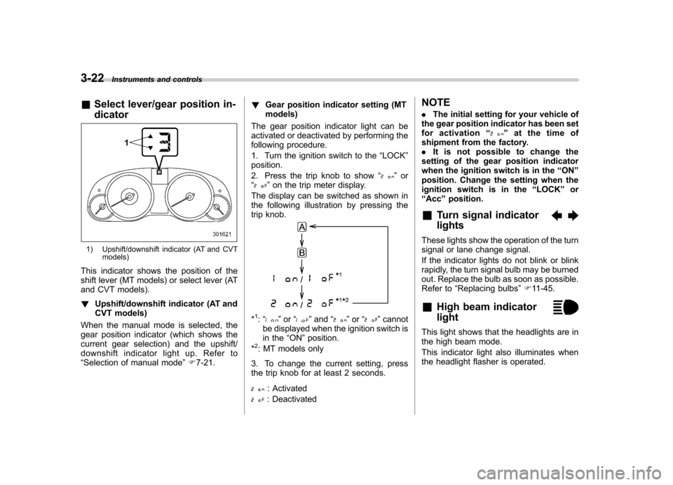
& Select lever/gear position in- dicator
1) Upshift/downshift indicator (AT and CVT
models)
This indicator shows the position of the
shift lever (MT models) or select lever (AT
and CVT models). ! Upshift/downshift indicator (AT and
CVT models)
When the manual mode is selected, the
gear position indicator (which shows the
current gear selection) and the upshift/
downshift indicator light up. Refer to“ Selection of manual mode ”F 7-21. !
Gear position indicator setting (MTmodels)
The gear position indicator light can be
activated or deactivated by performing the
following procedure.
1. Turn the ignition switch to the “LOCK ”
position.
2. Press the trip knob to show “
”or
“” on the trip meter display.
The display can be switched as shown in
the following illustration by pressing the
trip knob.
*1: “” or “”and “”or “”cannot
be displayed when the ignition switch is
in the “ON ”position.
*
2: MT models only
3. To change the current setting, press
the trip knob for at least 2 seconds.
: Activated
: Deactivated NOTE .
The initial setting for your vehicle of
the gear position indicator has been set
for activation “
”at the time of
shipment from the factory. . It is not possible to change the
setting of the gear position indicator
when the ignition switch is in the “ON ”
position. Change the setting when the
ignition switch is in the “LOCK ”or
“ Acc ”position.
& Turn signal indicator lights
These lights show the operation of the turn
signal or lane change signal.
If the indicator lights do not blink or blink
rapidly, the turn signal bulb may be burned
out. Replace the bulb as soon as possible.
Refer to “Replacing bulbs ”F 11-45.
& High beam indicator light
This light shows that the headlights are in
the high beam mode.
This indicator light also illuminates when
the headlight flasher is operated.