park assist SUBARU OUTBACK 2016 6.G Owners Manual
[x] Cancel search | Manufacturer: SUBARU, Model Year: 2016, Model line: OUTBACK, Model: SUBARU OUTBACK 2016 6.GPages: 572, PDF Size: 21.79 MB
Page 174 of 572
Instruments and controls/Warning and indicator lights
&Door open indicator
When any of the doors, the rear gate
(Outback) or the trunk lid (Legacy) is not
fully closed, the door open indicator
appears. This function is effective even if
the ignition switch is in the“LOCK”/“OFF”
or“ACC”position (all models) or the key is
removed from the ignition switch (models
without“keyless access with push-button
start system”).
The open door is indicated by the corre-
sponding part of the door open indicator.
Always make sure this indicator does not
appear before you start to drive.
&Windshield washer
fluid warning indicator
This indicator appears when the fluid level
in the windshield washer fluid tank de-
creases to the lower limit (approximately
0.6 US qt, 0.6 liter, 0.5 Imp qt).
&All-Wheel Drive warn-
ing light (CVT models)
WARNING
Continued driving with the AWD
warning light flashing can lead to
powertrain damage. If the AWD
warning light flashes, promptly parkin a safe place then check whether
all four tires are the same diameter
and whether any of the tires has a
puncture or has lost air pressure for
some other reason.
NOTE
If the temporary spare tire is used, the
AWD warning light may flash. Use of
the temporary spare tire should there-
fore be restricted to the minimum time
necessary. Replace the temporary
spare tire with a conventional tire as
soon as possible.
This light flashes if the vehicle is driven
with tires of different diameters fitted on its
wheels or with the air pressure exces-
sively low in any of its tires.
&Power steering warn-
ing light
While the engine is running, this warning
light illuminates when a malfunction has
been detected in the electric power steer-
ing system.
CAUTION
When the power steering warning
light is illuminated, there may be
more resistance when the steeringwheel is operated. Drive carefully to
the nearest SUBARU dealer and
have the vehicle inspected immedi-
ately.
NOTE
If the steering wheel is operated in the
following ways, the power steering
control system may temporarily limit
the power assist in order to prevent the
system components, such as the con-
trol computer and drive motor, from
overheating.
.The steering wheel is operated fre-
quently and turned sharply while the
vehicle is maneuvered at extremely low
speeds, such as while frequently turn-
ing the steering wheel during parallel
parking.
.The steering wheel remains in the
fully turned position for a long period
of time.
At this time, there will be more resis-
tance when steering. However this is
not a malfunction. Normal steering
force will be restored after the steering
wheel is not operated for a while and
the power steering control system has
an opportunity to cool down. However,
if the power steering is operated in a
non-standard way which causes power
3-22
Page 350 of 572

Starting and operating
X-mode (Outback CVT models)......................... 7-38
To activate/deactivate the X-mode....................... 7-39
Hill descent control function............................... 7-39
Tire pressure monitoring system (TPMS) (if
equipped)......................................................... 7-40
Parking your vehicle.......................................... 7-42
Electronic parking brake..................................... 7-42
Parking tips....................................................... 7-47
Hill start assist system (MT models)................ 7-48
To activate/deactivate the Hill start assist
system............................................................. 7-49
Cruise control..................................................... 7-49To set cruise control.......................................... 7-50
To temporarily cancel the cruise control............. 7-51To turn off the cruise control.............................. 7-51
To change the cruising speed............................ 7-51
Cruise control indicator..................................... 7-53
Cruise control set indicator................................ 7-53
BSD/RCTA (if equipped).................................... 7-53System features................................................. 7-53
System operation............................................... 7-55
BSD/RCTA approach indicator light/warning
buzzer............................................................. 7-56
BSD/RCTA warning indicator.............................. 7-58
BSD/RCTA OFF switch....................................... 7-59
Certification for the BSD/RCTA........................... 7-60
Handling of radar sensors.................................. 7-60
Page 358 of 572

Starting and operating/Starting and stopping the engine (models without push–button ignition switch)
when using the remote engine
start system).
NOTE
.Avoid rapid racing and rapid accel-
eration immediately after the engine
has started.
.For a short time after the engine has
started, the engine speed is kept high.
When the warm-up is completed, the
engine speed lowers automatically.
.On rare occasions, it may be difficult
to start the engine depending on the
fuel and the usage condition (repeated
driving of a distance in which the
engine has not warmed up sufficiently).
In such a case, it is recommended that
you change to a different brand of fuel.
.On rare occasions, transient knock-
ing may be heard from the engine when
the accelerator is operated rapidly
such as a rapid start-up and a rapid
acceleration. This is not a malfunction.
.The engine starts more easily when
the headlights, air conditioner and rear
window defogger are turned off.
.After the engine starts, the engine
speed will be kept high until the engine
has warmed up sufficiently.!MT models
1. Apply the parking brake.
2. Turn off unnecessary lights and ac-
cessories.
3. Depress the clutch pedal to the floor
and shift the shift lever into neutral. Hold
the clutch pedal to the floor while starting
the engine. The starter motor will only
operate when the clutch pedal is de-
pressed fully to the floor.
4. Turn the ignition switch to the“ON”
position and check the operation of the
warning and indicator lights. Refer to
“Warning and indicator lights”F3-12.
5. Turn the ignition switch to the“START”
positionwithoutdepressing the accelera-
tor pedal. Release the key immediately
after the engine has started.
If the engine does not start, perform the
following procedure.
(1) Turn the ignition switch to the
“LOCK”position and wait for at least
10 seconds. After checking that the
parking brake is applied, turn the
ignition switch to the“START”position
while depressing the accelerator pedal
slightly (approximately a quarter of the
full stroke). Release the accelerator
pedal as soon as the engine starts.
(2) If this fails to start the engine, turn
the ignition switch back to the“LOCK”position and wait for at least 10
seconds. Then fully depress the accel-
erator pedal and turn the ignition
switch to the“START”position. If the
engine starts, quickly release the
accelerator pedal.
(3) If this does not start the engine,
turn the ignition switch again to the
“LOCK”position. After waiting for 10
seconds or longer, turn the ignition
switch to the“START”position without
depressing the accelerator pedal.
(4) If the engine still refuses to start,
contact your nearest SUBARU dealer
for assistance.
6. Confirm that all warning and indicator
lights have turned off after the engine has
started. The fuel injection system auto-
matically lowers the idle speed as the
engine warms up.
!CVT models
CAUTION
If you restart the engine while the
vehicle is moving, shift the select
lever into the“N”position. Do not
attempt to place the select lever of a
moving vehicle into the“P”posi-
tion.
7-10
Page 359 of 572
1. Apply the parking brake.
2. Turn off unnecessary lights and ac-
cessories.
3. Shift the select lever to the“P”or“N”
position (preferably“P”position). The
starter will only operate when the select
lever is at the“P”or“N”position.
4. Turn the ignition switch to the“ON”
position and check the operation of the
warning and indicator lights. Refer to
“Warning and indicator lights”F3-12.
5. Turn the ignition switch to the“START”
positionwithoutdepressing the accelera-
tor pedal. Release the key immediately
after the engine has started.
If the engine does not start, perform the
following procedure.
(1) Turn the ignition switch to the
“LOCK”position and wait for at least
10 seconds. After checking that the
parking brake is applied, turn the
ignition switch to the“START”position
while depressing the accelerator pedal
slightly (approximately a quarter of the
full stroke). Release the accelerator
pedal as soon as the engine starts.
(2) If this fails to start the engine, turn
the ignition switch back to the“LOCK”
position and wait for at least 10
seconds. Then fully depress the accel-
erator pedal and turn the ignition
switch to the“START”position. If theengine starts, quickly release the
accelerator pedal.
(3) If this fails to start the engine, turn
the ignition switch again to the“LOCK”
position. After waiting for 10 seconds
or longer, turn the ignition switch to the
“START”position without depressing
the accelerator pedal.
(4) If the engine still refuses to start,
contact your nearest SUBARU dealer
for assistance.
6. Confirm that all warning and indicator
lights have turned off after the engine has
started. The fuel injection system auto-
matically lowers the idle speed as the
engine warms up.
While the engine is warming up, make
sure that the select lever is at the“P”or
“N”position and that the parking brake is
applied.
&Stopping the engine
WARNING
Do not stop the engine when the
vehicle is moving. This will cause
loss of power to the power steering
and the brake booster, making steer-
ing and braking more difficult. It
could also result in accidental acti-
vation of the“LOCK”position on theignition switch, causing the steering
wheel to lock.
The ignition switch should be turned off
only when the vehicle is stopped and the
engine is idling.
&Steering lock (models with-
out“keyless access with
push-button start system”)
After stopping the engine and the key is
removed from ignition switch, the steering
wheel will be locked due to the steering
lock function.
When the engine is restarted, the steering
lock will be automatically canceled.
!When the steering lock cannot be
released
When you cannot restart the engine due to
the steering lock, perform the following
steps.
!MT models
1. Check that the parking brake is ap-
plied.
2. Turn off unnecessary lights and ac-
cessories.
3. Depress the clutch pedal to the floor
and shift the shift lever into neutral. Hold
the clutch pedal to the floor while starting
the engine.
Starting and operating/Starting and stopping the engine (models without push–button ignition switch)
–CONTINUED–7-11
Page 375 of 572
!N (Neutral)
This position is for restarting a stalled
engine. In this position, the transmission is
neutral, meaning that the wheels and
transmission are not locked. Therefore,
the vehicle will roll freely, even on the
slightest incline unless the parking brake
or foot brake is applied.
Avoid coasting with the transmission in
neutral. Engine braking has no effect in
this condition.
WARNING
Do not drive the vehicle with the
select lever in the“N”(neutral)
position. Engine braking has no
effect in this condition and the risk
of an accident is consequently in-
creased.
NOTE
If the select lever is in the“N”position
when you stop the engine for parking,
you may not subsequently be able to
move it to the“R”and“P”positions. If
this happens, turn the ignition switch to
the“ON”position. You will then be able
to move the select lever to the“P”
position.!D (Drive)
This position is for normal driving. The
transmission shifts automatically and con-
tinuously into a suitable gear according to
the vehicle speed and the acceleration
you require. Also, while driving up and
down a hill, the transmission assists and
controls the driving performance and
engine braking while corresponding to
the road grade.
When more acceleration is required in“D”
position, depress the accelerator pedal
fully to the floor and hold that position. The
transmission will automatically downshift.
In this case, the transmission will operate
like a conventional automatic transmis-
sion. When you release the pedal, the
transmission will return to the original gear
position.
To use the manual mode, move the lever
from this position into the manual gate.
!While climbing a grade
When driving up a hill, undesired upshift is
prevented from taking place when the
accelerator is released. This minimizes
the chance of subsequent downshifting to
a lower gear when accelerating again.
This prevents repeated upshifting and
downshifting resulting in a smoother op-
eration of the vehicle.
NOTE
The transmission may downshift, de-
pending on the way the accelerator
pedal is depressed to accelerate the
vehicle again.
&Shift lock function
The shift lock function helps prevent the
improper operation of the select lever.
.The select lever cannot be operated
unless the ignition switch is turned to the
“ON”position and the brake pedal is
depressed.
.The select lever cannot be moved from
the“P”position to any other position
before the brake pedal is depressed.
Depress the brake pedal first, and then
operate the select lever.
.Only the“P”position allows you to turn
the key from the“ACC”position to the
“LOCK”position and remove the key from
the ignition key cylinder (models without
“keyless access with push-button start
system”).
.Only the“P”position allows you to turn
the push-button ignition switch to the
“OFF”position (models with“keyless
access with push-button start system”).
.If the ignition switch is turned to the
“LOCK”/“OFF”position while the select
lever is in the“N”position, the select lever
Starting and operating/Continuously variable transmission
–CONTINUED–7-27
Page 379 of 572
Power steering
Power steering warning light
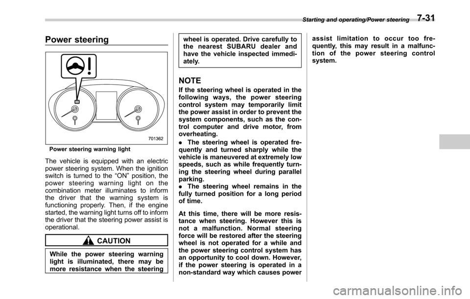
The vehicle is equipped with an electric
power steering system. When the ignition
switch is turned to the“ON”position, the
power steering warning light on the
combination meter illuminates to inform
the driver that the warning system is
functioning properly. Then, if the engine
started, the warning light turns off to inform
the driver that the steering power assist is
operational.
CAUTION
While the power steering warning
light is illuminated, there may be
more resistance when the steeringwheel is operated. Drive carefully to
the nearest SUBARU dealer and
have the vehicle inspected immedi-
ately.
NOTE
If the steering wheel is operated in the
following ways, the power steering
control system may temporarily limit
the power assist in order to prevent the
system components, such as the con-
trol computer and drive motor, from
overheating.
.The steering wheel is operated fre-
quently and turned sharply while the
vehicle is maneuvered at extremely low
speeds, such as while frequently turn-
ing the steering wheel during parallel
parking.
.The steering wheel remains in the
fully turned position for a long period
of time.
At this time, there will be more resis-
tance when steering. However this is
not a malfunction. Normal steering
force will be restored after the steering
wheel is not operated for a while and
the power steering control system has
an opportunity to cool down. However,
if the power steering is operated in a
non-standard way which causes powerassist limitation to occur too fre-
quently, this may result in a malfunc-
tion of the power steering control
system.
Starting and operating/Power steering7-31
Page 396 of 572
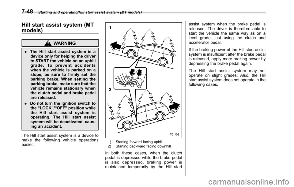
Starting and operating/Hill start assist system (MT models)
Hill start assist system (MT
models)
WARNING
.The Hill start assist system is a
device only for helping the driver
to START the vehicle on an uphill
grade. To prevent accidents
when the vehicle is parked on a
slope, be sure to firmly set the
parking brake. When setting the
parking brake, make sure that the
vehicle remains stationary when
the clutch pedal and brake pedal
are released.
.Do not turn the ignition switch to
the“LOCK”/“OFF”position while
the Hill start assist system is
operating. The Hill start assist
system will be deactivated, caus-
ing an accident.
The Hill start assist system is a device to
make the following vehicle operations
easier.
1) Starting forward facing uphill
2) Starting backward facing downhill
In both these cases, when the clutch
pedal is depressed while the brake pedal
is also depressed, braking power is
maintained temporarily by the Hill startassist system when the brake pedal is
released. The driver is therefore able to
start the vehicle the same way as on a
level grade, just using the clutch and
accelerator pedal.
If the braking power of the Hill start assist
system is insufficient after the brake pedal
is released, apply more braking power by
depressing the brake pedal again.
The Hill start assist system may not
operate on slight grades. Also, the Hill
start assist system does not operate in the
following cases.
7-48
Page 397 of 572
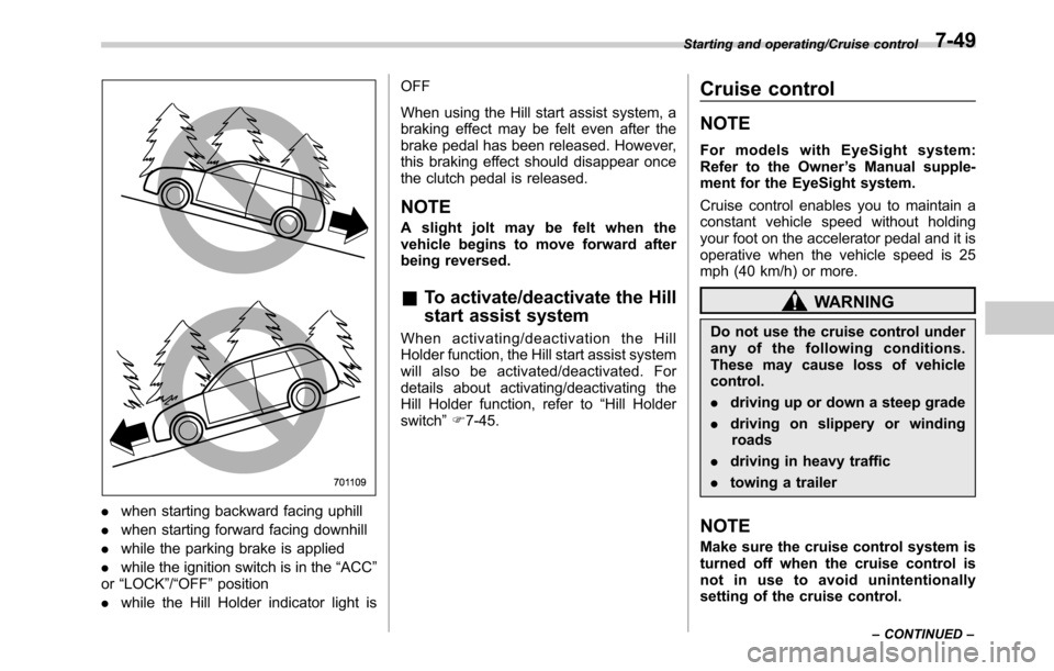
.when starting backward facing uphill
.when starting forward facing downhill
.while the parking brake is applied
.while the ignition switch is in the“ACC”
or“LOCK”/“OFF”position
.while the Hill Holder indicator light isOFF
When using the Hill start assist system, a
braking effect may be felt even after the
brake pedal has been released. However,
this braking effect should disappear once
the clutch pedal is released.
NOTE
A slight jolt may be felt when the
vehicle begins to move forward after
being reversed.
&To activate/deactivate the Hill
start assist system
When activating/deactivation the Hill
Holder function, the Hill start assist system
will also be activated/deactivated. For
details about activating/deactivating the
Hill Holder function, refer to“Hill Holder
switch”F7-45.
Cruise control
NOTE
For models with EyeSight system:
Refer to the Owner’s Manual supple-
ment for the EyeSight system.
Cruise control enables you to maintain a
constant vehicle speed without holding
your foot on the accelerator pedal and it is
operative when the vehicle speed is 25
mph (40 km/h) or more.
WARNING
Do not use the cruise control under
any of the following conditions.
These may cause loss of vehicle
control.
.driving up or down a steep grade
.driving on slippery or winding
roads
.driving in heavy traffic
.towing a trailer
NOTE
Make sure the cruise control system is
turned off when the cruise control is
not in use to avoid unintentionally
setting of the cruise control.
Starting and operating/Cruise control
–CONTINUED–7-49
Page 466 of 572

Appearance care/Corrosion protection
Corrosion protection
Your SUBARU has been designed and
built to resist corrosion. Special materials
and protective finishes have been used on
most parts of the vehicle to help maintain
fine appearance, strength, and reliable
operation.
&Most common causes of
corrosion
The most common causes of corrosion
are:
.The accumulation of moisture retaining
dirt and debris in body panel sections,
cavities, and other areas.
.Damage to paint and other protective
coatings caused by gravel and stone
chips or minor accidents.
Corrosion is accelerated on the vehicle
when:
.It is exposed to road salt or dust control
chemicals, or used in coastal areas where
there is more salt in the air, or in areas
where there is considerable industrial
pollution.
.It is driven in areas of high humidity,
especially when temperatures range just
above freezing.
.Dampness in certain parts of thevehicle remains for a long time, even
though other parts of the vehicle may be
dry.
.High temperatures will cause corrosion
to parts of the vehicle which cannot dry
quickly due to lack of proper ventilation.
&To help prevent corrosion
Wash the vehicle regularly to prevent
corrosion of the body and suspension
components. Also, wash the vehicle
promptly after driving on any of the
following surfaces.
.roads that have been salted to prevent
them from freezing in winter
.mud, sand, or gravel
.coastal roads
After the winter has ended, it is recom-
mended that the underbody be given a
very thorough washing.
Before the beginning of winter, check the
condition of underbody components, such
as the exhaust system, fuel and brake
lines, brake cables, suspension, steering
system, floor pan, and fenders. If any of
them are found to be rusted, they should
be given an appropriate rust prevention
treatment or should be replaced. Contact
your SUBARU dealer to perform this kind
of maintenance and treatment if you needassistance.
Repair chips and scratches in the paint as
soon as you find them.
Check the interior of the vehicle for water
and dirt accumulation under the floor mats
because that could cause corrosion.
Occasionally check under the mats to
make sure the area is dry.
Keep your garage dry. Do not park your
vehicle in a damp, poorly ventilated
garage. In such a garage, corrosion can
be caused by dampness. If you wash the
vehicle in the garage or put the vehicle
into the garage when wet or covered with
snow, that can cause dampness.
If your vehicle is operated in cold weather
and/or in areas where road salts and other
corrosive materials are used, the door
hinges and locks, trunk lid lock, and hood
latch should be inspected and lubricated
periodically.
10-4
Page 557 of 572

Booster seat.............................................................. 1-34
Bottle holder................................................................ 6-9
Brake
Assist................................................................... 7-32
Booster........................................................ 7-32, 11-22
Disc..................................................................... 12-9
Fluid............................................................ 11-19, 12-8
Pad ..................................................................... 11-24
Parking................................................................. 7-42
Pedal.................................................................. 11-22
System................................................................. 7-32
Brake pedal
Free play............................................................. 11-22
Reserve distance.................................................. 11-23
Brake system............................................................ 7-32
Warning light......................................................... 3-18
Braking..................................................................... 7-32
Tips...................................................................... 7-32
Breaking-in of new brake pads................................... 11-24
BSD/RCTA................................................................ 7-53
Approach indicator light/warning buzzer.................... 7-56
OFF indicator........................................ 3-31, 3-38, 7-56
OFF switch........................................................... 7-59
Warning indicator................................... 3-31, 3-38, 7-58
Warning volume..................................................... 3-42
Bulb
Chart.................................................................. 12-14
Replacing............................................................. 11-40C
Cargo area
Cover.................................................................... 6-16
Light............................................................. 6-3, 11-49
Tie-down hooks...................................................... 6-19
Catalytic converter....................................................... 8-3
Center
Console................................................................. 6-6
Changing
Coolant............................................................... 11-15
Flat tire.................................................................. 9-5
Oil and oil filter..................................................... 11-13
Charge warning light................................................... 3-15
CHECK ENGINE warning light/Malfunction indicator
light....................................................................... 3-15
Checking
Brake pedal free play............................................ 11-22
Brake pedal reserve distance................................. 11-23
Clutch function..................................................... 11-23
Clutch pedal free play........................................... 11-23
Coolant level........................................................ 11-14
Fluid level (brake fluid).......................................... 11-19
Fluid level (clutch fluid).......................................... 11-21
Fluid level (washer fluid)........................................ 11-32
Oil level (engine oil).............................................. 11-11
Child restraint systems................................................ 1-27
Installation of a booster seat.................................... 1-34
Installation with A/ELR seatbelt................................ 1-30
Lower and tether anchorages
................................... 1-35
Top tether anchorages............................................ 1-38
Child safety................................................................... 4
Index14-3