Trim SUBARU TRIBECA 2009 1.G Service Workshop Manual
[x] Cancel search | Manufacturer: SUBARU, Model Year: 2009, Model line: TRIBECA, Model: SUBARU TRIBECA 2009 1.GPages: 2453, PDF Size: 46.32 MB
Page 1190 of 2453
![SUBARU TRIBECA 2009 1.G Service Workshop Manual EN(H6DO)(diag)-29
Subaru Select Monitor
ENGINE (DIAGNOSTICS)
5. READ CURRENT DATA FOR ENGINE (OBD MODE)
1) On the «Main Menu» display screen, select the {Each System Check} and press the [YES] key.
SUBARU TRIBECA 2009 1.G Service Workshop Manual EN(H6DO)(diag)-29
Subaru Select Monitor
ENGINE (DIAGNOSTICS)
5. READ CURRENT DATA FOR ENGINE (OBD MODE)
1) On the «Main Menu» display screen, select the {Each System Check} and press the [YES] key.](/img/17/7322/w960_7322-1189.png)
EN(H6DO)(diag)-29
Subaru Select Monitor
ENGINE (DIAGNOSTICS)
5. READ CURRENT DATA FOR ENGINE (OBD MODE)
1) On the «Main Menu» display screen, select the {Each System Check} and press the [YES] key.
2) On the «System Selection Menu» display screen, select the {Engine} and press the [YES] key.
3) Press the [YES] key after the information of engine type has been displayed.
4) On the «Engine Diagnosis» display screen, select the {OBD System} and press the [YES] key.
5) On the «OBD Menu» display screen, select the {Current Data Display/Save}, and then press the [YES]
key.
6) On the «Data Display Menu» screen, select the {Data Display} and press the [YES] key.
7) Using the scroll key, scroll the display screen up or down until the desired data is shown.
•A list of the support data is shown in the following table.
AT c o o r d i n a t e f u e l c u t d e m a n d s i g n a l AT c o o r d i n a t e f u e l c u t d e m a n d — O F F
Ve h i c l e d y n a m i c s c o n t r o l ( V D C ) t o r q u e d o w n
prohibition outputBan of Torque Down — Permission
Ve h i c l e d y n a m i c s c o n t r o l ( V D C ) t o r q u e d o w n
demandVDC torque down demand — OFF
AT c o o r d i n a t e p e r m i s s i o n s i g n a l AT c o o r d i n a t e p e r m i s s i o n s i g n a l — P e r m i s s i o n
Electronic throttle control motor relay signal ETC motor relay — ON
Stop light switch signal Stop Light Switch — OFF
SET/COAST switch signal SET/COAST SW — OFF
RESUME/ACCEL switch signal RESUME/ACCEL SW — OFF
Brake switch signal Brake SW — OFF
Main switch signal Main SW — OFF
Body integrated unit data reception Body Int. Unit Data — Yes
Body integlated unit counter update Body Int. Unit Count — Yes
Cruise control cancel switch signal CC Cancel SW — OFF
Va r i a b l e v a l v e l i f t d i a g n o s i s o i l p r e s s u r e sw i t c h
signal 1Oil Temperature SW1 — ON
Va r i a b l e v a l v e l i f t d i a g n o s i s o i l p r e s s u r e sw i t c h
signal 2Oil Temperature SW2 — ON
Description Display Unit of measure
Number of diagnosis code Number of Diag. Codes: 0
Condition of malfunction indicator light MI (MIL) ON or OFF
Monitoring test of misfire Misfire monitoring Finish
Monitoring test of fuel system Fuel system monitoring Finish
Monitoring test of comprehensive component Component monitoring Finish
Te s t o f c a t a l y s t C a t a l y s t D i a g n o s i s F i n i s h o r i n c o m p l e t e
Te s t o f h e a t i n g - t y p e c a t a l y s t H e a t e d c a t a l y s t N o
Te s t o f e v a p o r a t i v e e m i s s i o n p u r g e c o n t r o l s y s t e m E v a p o r a t i v e p u r g e s y s t e m F i n i s h o r i n c o m p l e t e
Te s t o f s e c o n d a r y a i r s y s t e m S e c o n d a r y a i r s y s t e m N o
Te s t o f a i r c o n d i t i o n i n g s y s t e m r e f r i g e r a n t A / C s y s t e m r e f r i g e r a n t N o
Te s t o f o x y g e n s e n s o r O x y g e n s e n o r F i n i s h o r i n c o m p l e t e
Te s t o f o x y g e n s e n s o r h e a t e r O x y g e n s e n s o r h e a t e r F i n i s h
Te s t o f E G R s y s t e m E G R s y s t e m N o s u p p o r t
A/F control #1 Fuel system for Bank 1 OPEN early period
A/F control #2 Fuel system for Bank 2 OPEN early period
Calculated load valve Calculated load valve %
Engine coolant temperature Coolant Temp. °C
A/F compensation #1 Short term fuel trim B1 %
A/F learning #1 Long term fuel trim B1 %
A/F compensation #2 Short term fuel trim #2 %
A/F learning #2 Long term fuel trim B2 %
Description Display Unit of measure Note (at idling)
Page 1191 of 2453
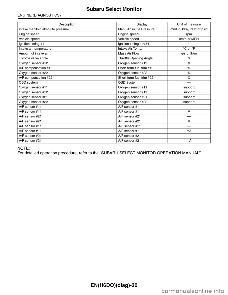
EN(H6DO)(diag)-30
Subaru Select Monitor
ENGINE (DIAGNOSTICS)
NOTE:
For detailed operation procedure, refer to the “SUBARU SELECT MONITOR OPERATION MANUAL”.
Intake manifold absolute pressure Mani. Absolute Pressure mmHg, kPa, inHg or psig
Engine speed Engine speed rpm
Ve h i c l e s p e e d Ve h i c l e s p e e d k m / h o r M P H
Ignition timing #1 Ignition timing adv.#1 °
Intake air temperature Intake Air Temp. °C or °F
Amount of intake air Mass Air Flow g/s or lb/m
Throttle valve angle Throttle Opening Angle %
Oxygen sensor #12 Oxygen sensor #12 V
A/F compensation #12 Short term fuel trim #12 %
Oxygen sensor #22 Oxygen sensor #22 %
A/F compensation #22 Short term fuel trim #22 %
OBD system OBD System —
Oxygen sensor #11 Oxygen sensor #11 support
Oxygen sensor #12 Oxygen sensor #12 support
Oxygen sensor #21 Oxygen sensor #21 support
Oxygen sensor #22 Oxygen sensor #22 support
A/F sensor #11 A/F sensor #11 —
A/F sensor #11 A/F sensor #11 V
A/F sensor #21 A/F sensor #21 —
A/F sensor #21 A/F sensor #21 V
A/F sensor #11 A/F sensor #11 —
A/F sensor #11 A/F sensor #11 mA
A/F sensor #21 A/F sensor #21 —
A/F sensor #21 A/F sensor #21 mA
Description Display Unit of measure
Page 1192 of 2453
![SUBARU TRIBECA 2009 1.G Service Workshop Manual EN(H6DO)(diag)-31
Subaru Select Monitor
ENGINE (DIAGNOSTICS)
6. READ FREEZE FRAME DATA FOR ENGINE (OBD MODE)
1) On the «Main Menu» display screen, select the {Each System Check} and press the [YES] SUBARU TRIBECA 2009 1.G Service Workshop Manual EN(H6DO)(diag)-31
Subaru Select Monitor
ENGINE (DIAGNOSTICS)
6. READ FREEZE FRAME DATA FOR ENGINE (OBD MODE)
1) On the «Main Menu» display screen, select the {Each System Check} and press the [YES]](/img/17/7322/w960_7322-1191.png)
EN(H6DO)(diag)-31
Subaru Select Monitor
ENGINE (DIAGNOSTICS)
6. READ FREEZE FRAME DATA FOR ENGINE (OBD MODE)
1) On the «Main Menu» display screen, select the {Each System Check} and press the [YES] key.
2) On the «System Selection Menu» display screen, select the {Engine} and press the [YES] key.
3) Press the [YES] key after the information of engine type has been displayed.
4) On the «Engine Diagnosis» display screen, select the {OBD System} and press the [YES] key.
5) On the «OBD Menu» display screen, select the {Freeze Frame Data} and press the [YES] key.
•A list of the support data is shown in the following table.
NOTE:
For detailed operation procedure, refer to the “SUBARU SELECT MONITOR OPERATION MANUAL”.
Description Display Unit of measure
DTC of freeze frame data Freeze frame data DTC
Air fuel ratio control system for bank 1 Fuel system for Bank1 —
Air fuel ratio control system for bank 2 Fuel system for Bank2 —
Engine load data Engine Load %
Engine coolant temperature signal Coolant Temp. °C or °F
Short term fuel trim by front oxygen (A/F) sensor (Bank 1) Short term fuel trim B1 %
Long term fuel trim by front oxygen (A/F) sensor (Bank 1) Long term fuel trim B1 %
Short term fuel trim by front oxygen (A/F) sensor (Bank 2) Short term fuel trim B2 %
Long term fuel trim by front oxygen (A/F) sensor (Bank 2) Long term fuel trim B2 %
Intake manifold absolute pressure signal Mani. Absolute Pressure mmHg, kPa, inHg or psig
Engine speed signal Engine Speed rpm
Ve h i c l e s p e e d s i g n a l Ve h i c l e S p e e d k m / h o r M P H
Ignition timing #1 Ignition timing adv. #1 °
Intake air temperature Intake Air Temp. °C
Amount of intake air Mass Air Flow g/s
Throttle valve angle Throttle Opening Angle %
Oxygen sensor #12 Oxygen sensor #12 V
A/F compensation #12 Short term fuel trim #12 %
Oxygen sensor #22 Oxygen sensor #22 V
A/F compensation #12 Short term fuel trim #22 %
Oxygen sensor #11 Oxygen sensor #11 support
Oxygen sensor #12 Oxygen sensor #12 support
Oxygen sensor #21 Oxygen sensor #21 support
Oxygen sensor #22 Oxygen sensor #22 support
Page 1202 of 2453
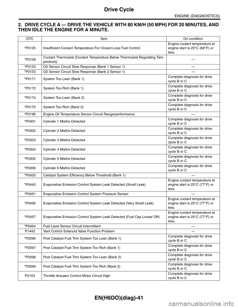
EN(H6DO)(diag)-41
Drive Cycle
ENGINE (DIAGNOSTICS)
2. DRIVE CYCLE A — DRIVE THE VEHICLE WITH 80 KM/H (50 MPH) FOR 20 MINUTES, AND
THEN IDLE THE ENGINE FOR A MINUTE.
DTC Item On condition
*P0125 Insufficient Coolant Temperature For Closed Loop Fuel Control
Engine coolant temperature at
engine start is 20°C (68°F) or
less.
*P0128Coolant Thermostat (Coolant Temperature Below Thermostat Regulating Tem-
perature)—
*P0133 O2 Sensor Circuit Slow Response (Bank 1 Sensor 1) —
*P0153 O2 Sensor Circuit Slow Response (Bank 2 Sensor 1) —
*P0171 System Too Lean (Bank 1)Complete diagnosis for drive
cycle B or C
*P0172 System Too Rich (Bank 1)Complete diagnosis for drive
cycle B or C
*P0174 System Too Lean (Bank 2)Complete diagnosis for drive
cycle B or C
*P0175 System Too Rich (Bank 2)Complete diagnosis for drive
cycle B or C
*P0196 Engine Oil Temperature Sensor Circuit Range/performance —
*P0301 Cylinder 1 Misfire DetectedComplete diagnosis for drive
cycle B or C
*P0302 Cylinder 2 Misfire DetectedComplete diagnosis for drive
cycle B or C
*P0303 Cylinder 3 Misfire DetectedComplete diagnosis for drive
cycle B or C
*P0304 Cylinder 4 Misfire DetectedComplete diagnosis for drive
cycle B or C
*P0305 Cylinder 5 Misfire DetectedComplete diagnosis for drive
cycle B or C
*P0306 Cylinder 6 Misfire DetectedComplete diagnosis for drive
cycle B or C
*P0420 Catalyst System Efficiency Below Threshold (Bank 1) —
*P0442 Evaporative Emission Control System Leak Detected (Small Leak)
Engine coolant temperature at
engine start is 25°C (77°F) or
less.
*P0451 Evaporative Emission Control System Pressure Sensor —
*P0456 Evaporative Emission Control System Leak Detected (Very Small Leak)
Engine coolant temperature at
engine start is 25°C (77°F) or
less.
*P0457 Evaporative Emission Control System Leak Detected (Fuel Cap Loose/ Off)
Engine coolant temperature at
engine start is 25°C (77°F) or
less.
*P0464 Fuel Level Sensor Circuit Intermittent —
P1443 Vent Control Solenoid Valve Function Problem —
*P2096 Post Catalyst Fuel Trim System Too Lean (Bank 1)Complete diagnosis for drive
cycle B or C
*P2097 Post Catalyst Fuel Trim System Too Rich (Bank 1)Complete diagnosis for drive
cycle B or C
*P2098 Post Catalyst Fuel Trim System Too Lean (Bank 2)Complete diagnosis for drive
cycle B or C
*P2099 Post Catalyst Fuel Trim System Too Rich (Bank 2)Complete diagnosis for drive
cycle B or C
P2103 Throttle Actuator Control Motor Circuit HighComplete diagnosis for drive
cycle B or C
Page 1203 of 2453
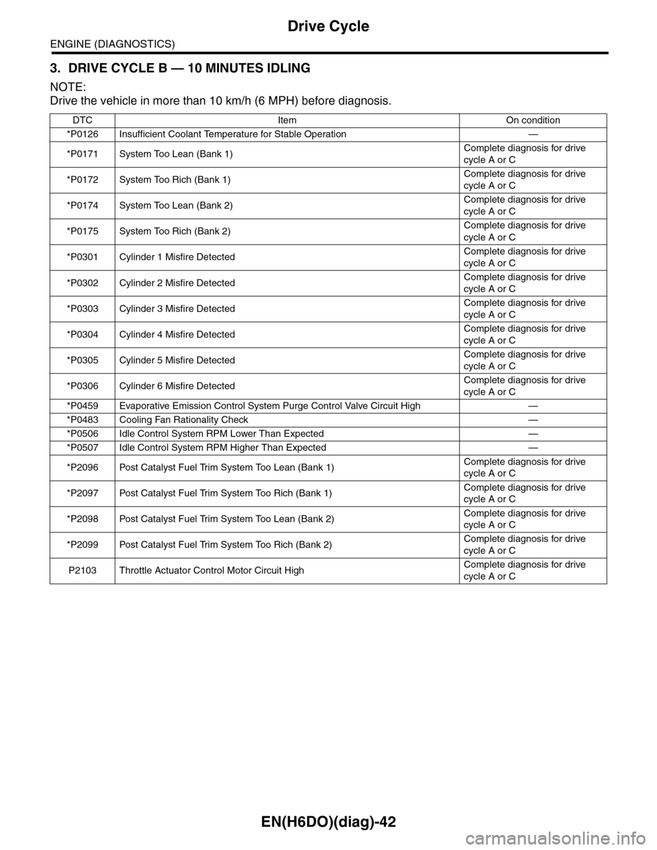
EN(H6DO)(diag)-42
Drive Cycle
ENGINE (DIAGNOSTICS)
3. DRIVE CYCLE B — 10 MINUTES IDLING
NOTE:
Drive the vehicle in more than 10 km/h (6 MPH) before diagnosis.
DTC Item On condition
*P0126 Insufficient Coolant Temperature for Stable Operation —
*P0171 System Too Lean (Bank 1)Complete diagnosis for drive
cycle A or C
*P0172 System Too Rich (Bank 1)Complete diagnosis for drive
cycle A or C
*P0174 System Too Lean (Bank 2)Complete diagnosis for drive
cycle A or C
*P0175 System Too Rich (Bank 2)Complete diagnosis for drive
cycle A or C
*P0301 Cylinder 1 Misfire DetectedComplete diagnosis for drive
cycle A or C
*P0302 Cylinder 2 Misfire DetectedComplete diagnosis for drive
cycle A or C
*P0303 Cylinder 3 Misfire DetectedComplete diagnosis for drive
cycle A or C
*P0304 Cylinder 4 Misfire DetectedComplete diagnosis for drive
cycle A or C
*P0305 Cylinder 5 Misfire DetectedComplete diagnosis for drive
cycle A or C
*P0306 Cylinder 6 Misfire DetectedComplete diagnosis for drive
cycle A or C
*P0459 Evaporative Emission Control System Purge Control Valve Circuit High —
*P0483 Cooling Fan Rationality Check —
*P0506 Idle Control System RPM Lower Than Expected —
*P0507 Idle Control System RPM Higher Than Expected —
*P2096 Post Catalyst Fuel Trim System Too Lean (Bank 1)Complete diagnosis for drive
cycle A or C
*P2097 Post Catalyst Fuel Trim System Too Rich (Bank 1)Complete diagnosis for drive
cycle A or C
*P2098 Post Catalyst Fuel Trim System Too Lean (Bank 2)Complete diagnosis for drive
cycle A or C
*P2099 Post Catalyst Fuel Trim System Too Rich (Bank 2)Complete diagnosis for drive
cycle A or C
P2103 Throttle Actuator Control Motor Circuit HighComplete diagnosis for drive
cycle A or C
Page 1236 of 2453
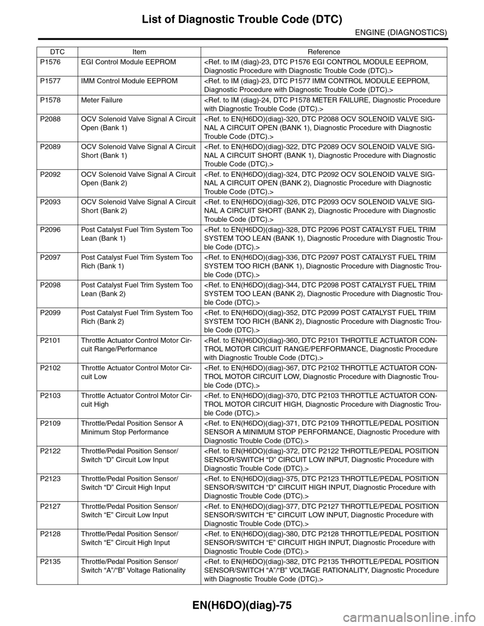
EN(H6DO)(diag)-75
List of Diagnostic Trouble Code (DTC)
ENGINE (DIAGNOSTICS)
P1576 EGI Control Module EEPROM
P1577 IMM Control Module EEPROM
P1578 Meter Failure
P2088 OCV Solenoid Valve Signal A Circuit
Open (Bank 1)
Tr o u b l e C o d e ( D T C ) . >
P2089 OCV Solenoid Valve Signal A Circuit
Short (Bank 1)
Tr o u b l e C o d e ( D T C ) . >
P2092 OCV Solenoid Valve Signal A Circuit
Open (Bank 2)
Tr o u b l e C o d e ( D T C ) . >
P2093 OCV Solenoid Valve Signal A Circuit
Short (Bank 2)
Tr o u b l e C o d e ( D T C ) . >
P2096 Post Catalyst Fuel Trim System Too
Lean (Bank 1)
ble Code (DTC).>
P2097 Post Catalyst Fuel Trim System Too
Rich (Bank 1)
ble Code (DTC).>
P2098 Post Catalyst Fuel Trim System Too
Lean (Bank 2)
ble Code (DTC).>
P2099 Post Catalyst Fuel Trim System Too
Rich (Bank 2)
ble Code (DTC).>
P2101 Throttle Actuator Control Motor Cir-
cuit Range/Performance
with Diagnostic Trouble Code (DTC).>
P2102 Throttle Actuator Control Motor Cir-
cuit Low
ble Code (DTC).>
P2103 Throttle Actuator Control Motor Cir-
cuit High
ble Code (DTC).>
P2109 Throttle/Pedal Position Sensor A
Minimum Stop Performance
Diagnostic Trouble Code (DTC).>
P2122 Throttle/Pedal Position Sensor/
Switch “D” Circuit Low Input
Diagnostic Trouble Code (DTC).>
P2123 Throttle/Pedal Position Sensor/
Switch “D” Circuit High Input
Diagnostic Trouble Code (DTC).>
P2127 Throttle/Pedal Position Sensor/
Switch “E” Circuit Low Input
Diagnostic Trouble Code (DTC).>
P2128 Throttle/Pedal Position Sensor/
Switch “E” Circuit High Input
Diagnostic Trouble Code (DTC).>
P2135 Throttle/Pedal Position Sensor/
Switch “A”/“B” Voltage Rationality
with Diagnostic Trouble Code (DTC).>
DTC Item Reference
Page 1489 of 2453
EN(H6DO)(diag)-328
Diagnostic Procedure with Diagnostic Trouble Code (DTC)
ENGINE (DIAGNOSTICS)
DQ:DTC P2096 POST CATALYST FUEL TRIM SYSTEM TOO LEAN (BANK 1)
DTC DETECTING CONDITION:
•Detected when two consecutive driving cycles with fault occur.
•GENERAL DESCRIPTION
CAUTION:
After repair or replacement of faulty parts, perform Clear Memory Mode
Page 1497 of 2453
EN(H6DO)(diag)-336
Diagnostic Procedure with Diagnostic Trouble Code (DTC)
ENGINE (DIAGNOSTICS)
DR:DTC P2097 POST CATALYST FUEL TRIM SYSTEM TOO RICH (BANK 1)
DTC DETECTING CONDITION:
•Detected when two consecutive driving cycles with fault occur.
•GENERAL DESCRIPTION
CAUTION:
After repair or replacement of faulty parts, perform Clear Memory Mode
Page 1505 of 2453
EN(H6DO)(diag)-344
Diagnostic Procedure with Diagnostic Trouble Code (DTC)
ENGINE (DIAGNOSTICS)
DS:DTC P2098 POST CATALYST FUEL TRIM SYSTEM TOO LEAN (BANK 2)
DTC DETECTING CONDITION:
•Detected when two consecutive driving cycles with fault occur.
•GENERAL DESCRIPTION
CAUTION:
After repair or replacement of faulty parts, perform Clear Memory Mode
Page 1513 of 2453
EN(H6DO)(diag)-352
Diagnostic Procedure with Diagnostic Trouble Code (DTC)
ENGINE (DIAGNOSTICS)
DT:DTC P2099 POST CATALYST FUEL TRIM SYSTEM TOO RICH (BANK 2)
DTC DETECTING CONDITION:
•Detected when two consecutive driving cycles with fault occur.
•GENERAL DESCRIPTION
CAUTION:
After repair or replacement of faulty parts, perform Clear Memory Mode