Trim SUBARU TRIBECA 2009 1.G Service Workshop Manual
[x] Cancel search | Manufacturer: SUBARU, Model Year: 2009, Model line: TRIBECA, Model: SUBARU TRIBECA 2009 1.GPages: 2453, PDF Size: 46.32 MB
Page 1593 of 2453
FU(H6DO)-32
Engine Control Module (ECM)
FUEL INJECTION (FUEL SYSTEMS)
16.Engine Control Module (ECM)
A: REMOVAL
1) Disconnect the ground cable from battery.
2) Remove the front pillar lower trim and console
side panel lower RH of passenger's side.
3) Detach the floor mat of passenger's seat.
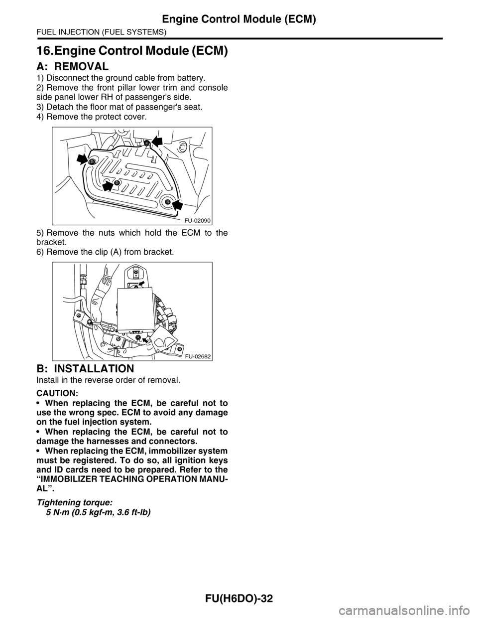
4) Remove the protect cover.
5) Remove the nuts which hold the ECM to the
bracket.
6) Remove the clip (A) from bracket.
B: INSTALLATION
Install in the reverse order of removal.
CAUTION:
•When replacing the ECM, be careful not to
use the wrong spec. ECM to avoid any damage
on the fuel injection system.
•When replacing the ECM, be careful not to
damage the harnesses and connectors.
•When replacing the ECM, immobilizer system
must be registered. To do so, all ignition keys
and ID cards need to be prepared. Refer to the
“IMMOBILIZER TEACHING OPERATION MANU-
AL”.
Tightening torque:
5 N·m (0.5 kgf-m, 3.6 ft-lb)
FU-02090
FU-02682
Page 1597 of 2453
FU(H6DO)-36
Fuel Pump Control Unit
FUEL INJECTION (FUEL SYSTEMS)
20.Fuel Pump Control Unit
A: REMOVAL
1) Disconnect the ground cable from battery.
2) Remove the rear quarter trim.
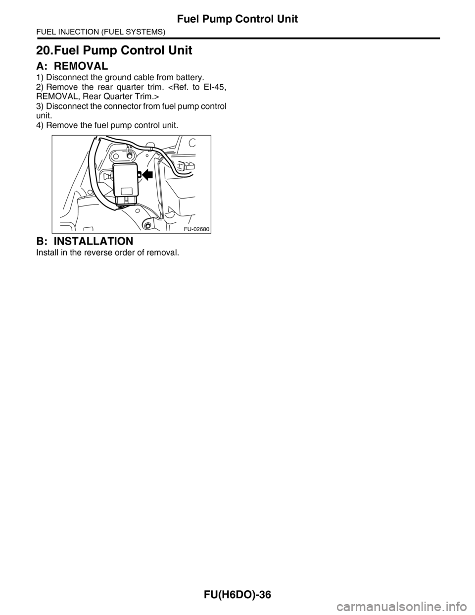
3) Disconnect the connector from fuel pump control
unit.
4) Remove the fuel pump control unit.
B: INSTALLATION
Install in the reverse order of removal.
FU-02680
Page 1619 of 2453
GD(H6DO)-7
List of Diagnostic Trouble Code (DTC)
GENERAL DESCRIPTION
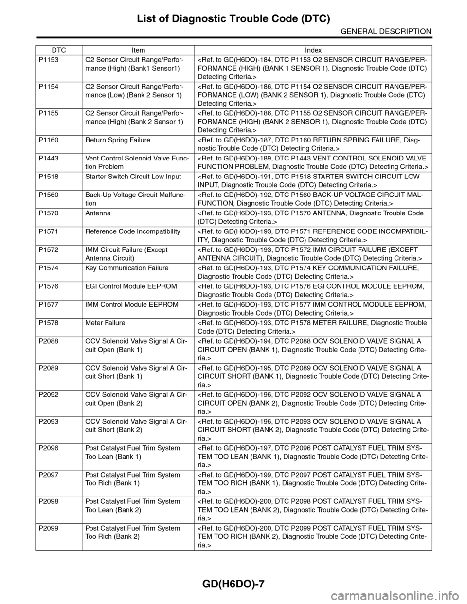
P1153 O2 Sensor Circuit Range/Perfor-
mance (High) (Bank1 Sensor1)
Detecting Criteria.>
P1154 O2 Sensor Circuit Range/Perfor-
mance (Low) (Bank 2 Sensor 1)
Detecting Criteria.>
P1155 O2 Sensor Circuit Range/Perfor-
mance (High) (Bank 2 Sensor 1)
Detecting Criteria.>
P1160 Return Spring Failure
P1443 Vent Control Solenoid Valve Func-
tion Problem
P1518 Starter Switch Circuit Low Input
P1560 Back-Up Voltage Circuit Malfunc-
tion
P1570 Antenna
P1571 Reference Code Incompatibility
P1572 IMM Circuit Failure (Except
Antenna Circuit)
P1574 Key Communication Failure
P1576 EGI Control Module EEPROM
P1577 IMM Control Module EEPROM
P1578 Meter Failure
P2088 OCV Solenoid Valve Signal A Cir-
cuit Open (Bank 1)
ria.>
P2089 OCV Solenoid Valve Signal A Cir-
cuit Short (Bank 1)
ria.>
P2092 OCV Solenoid Valve Signal A Cir-
cuit Open (Bank 2)
ria.>
P2093 OCV Solenoid Valve Signal A Cir-
cuit Short (Bank 2)
ria.>
P2096 Post Catalyst Fuel Trim System
To o L e a n ( B a n k 1 )
ria.>
P2097 Post Catalyst Fuel Trim System
To o R i c h ( B a n k 1 )
ria.>
P2098 Post Catalyst Fuel Trim System
To o L e a n ( B a n k 2 )
ria.>
P2099 Post Catalyst Fuel Trim System
To o R i c h ( B a n k 2 )
ria.>
DTC Item Index
Page 1809 of 2453
GD(H6DO)-197
Diagnostic Trouble Code (DTC) Detecting Criteria
GENERAL DESCRIPTION
DY:DTC P2096 POST CATALYST FUEL TRIM SYSTEM TOO LEAN (BANK 1)
1. OUTLINE OF DIAGNOSIS
Detect the malfunction of fuel system from the size of the sub feedback learning value.
Control the sub feedback learning and judge as NG when the learning value is in the lean zone.
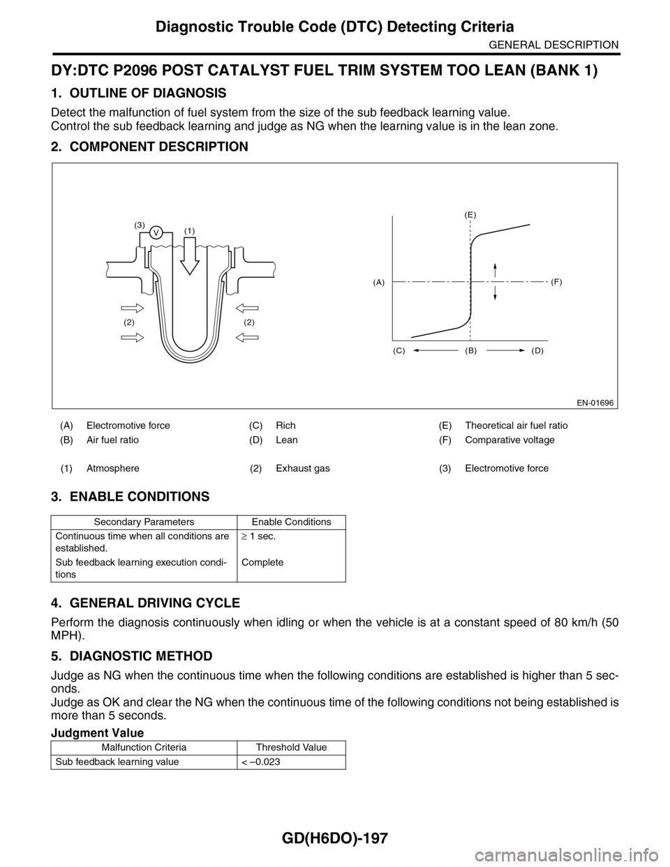
2. COMPONENT DESCRIPTION
3. ENABLE CONDITIONS
4. GENERAL DRIVING CYCLE
Perform the diagnosis continuously when idling or when the vehicle is at a constant speed of 80 km/h (50
MPH).
5. DIAGNOSTIC METHOD
Judge as NG when the continuous time when the following conditions are established is higher than 5 sec-
onds.
Judge as OK and clear the NG when the continuous time of the following conditions not being established is
more than 5 seconds.
(A) Electromotive force (C) Rich (E) Theoretical air fuel ratio
(B) Air fuel ratio (D) Lean (F) Comparative voltage
(1) Atmosphere (2) Exhaust gas (3) Electromotive force
Secondary Parameters Enable Conditions
Continuous time when all conditions are
established.
≥ 1 sec.
Sub feedback learning execution condi-
tions
Complete
Judgment Value
Malfunction Criteria Threshold Value
Sub feedback learning value < –0.023
EN-01696
(3)V(1)
(2) (2)
(E)
(F)
(C) (B) (D)
(A)
Page 1811 of 2453
GD(H6DO)-199
Diagnostic Trouble Code (DTC) Detecting Criteria
GENERAL DESCRIPTION
DZ:DTC P2097 POST CATALYST FUEL TRIM SYSTEM TOO RICH (BANK 1)
1. OUTLINE OF DIAGNOSIS
Detect the malfunction of fuel system from the size of the sub feedback learning value.
Sub feedback learning is being performed. When the learning value goes to the rich side, judge as NG.
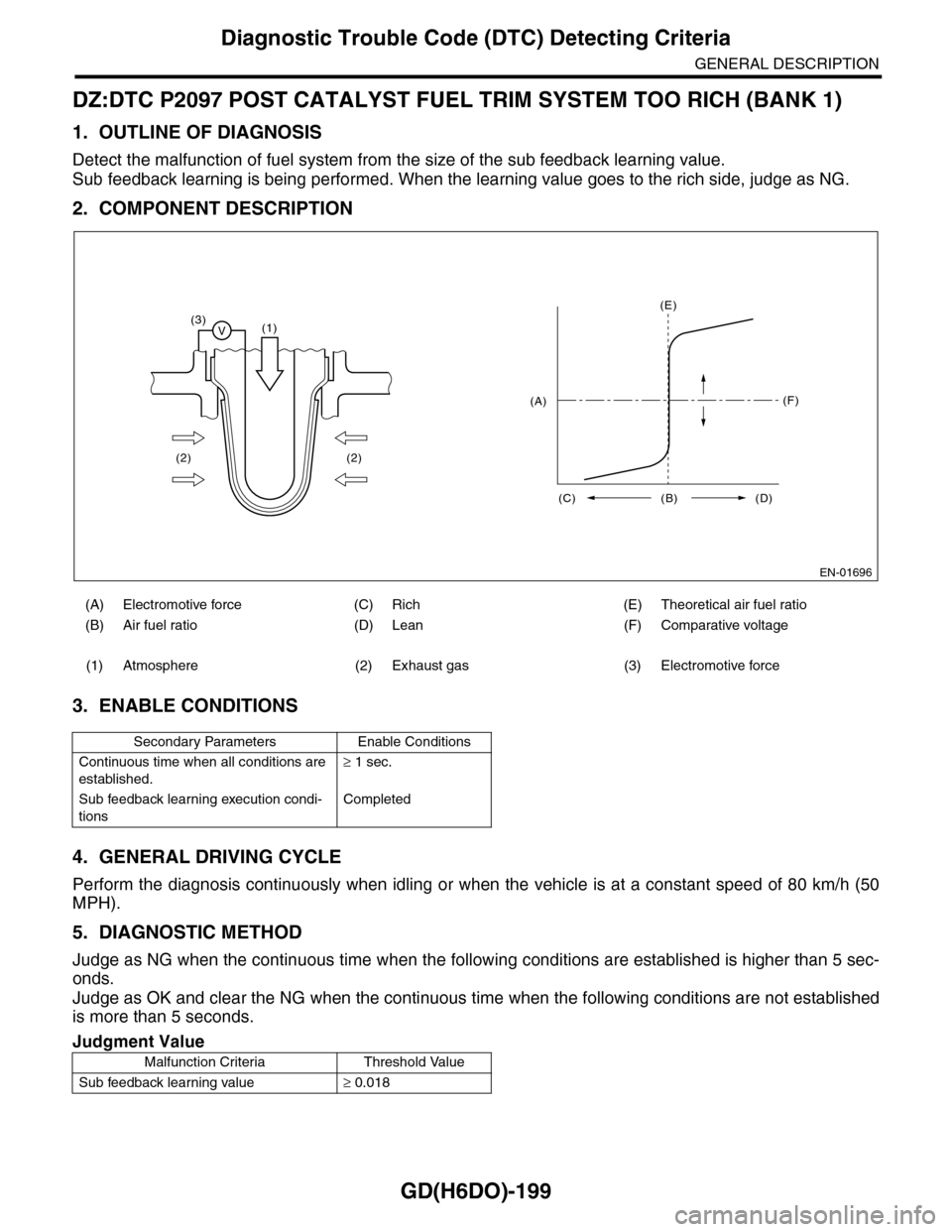
2. COMPONENT DESCRIPTION
3. ENABLE CONDITIONS
4. GENERAL DRIVING CYCLE
Perform the diagnosis continuously when idling or when the vehicle is at a constant speed of 80 km/h (50
MPH).
5. DIAGNOSTIC METHOD
Judge as NG when the continuous time when the following conditions are established is higher than 5 sec-
onds.
Judge as OK and clear the NG when the continuous time when the following conditions are not established
is more than 5 seconds.
(A) Electromotive force (C) Rich (E) Theoretical air fuel ratio
(B) Air fuel ratio (D) Lean (F) Comparative voltage
(1) Atmosphere (2) Exhaust gas (3) Electromotive force
Secondary Parameters Enable Conditions
Continuous time when all conditions are
established.
≥ 1 sec.
Sub feedback learning execution condi-
tions
Completed
Judgment Value
Malfunction Criteria Threshold Value
Sub feedback learning value≥ 0.018
EN-01696
(3)V(1)
(2) (2)
(E)
(F)
(C) (B) (D)
(A)
Page 1812 of 2453
GD(H6DO)-200
Diagnostic Trouble Code (DTC) Detecting Criteria
GENERAL DESCRIPTION
Time Needed for Diagnosis: 5 seconds
Malfunction Indicator Light Illumination: Illuminates when malfunctions occur in 2 continuous driving cy-
cles.
6. DTC CLEAR CONDITION
•When the OK idling cycle is completed 40 times in a row
•When “Clear Memory” is performed
7. MALFUNCTION INDICATOR LIGHT CLEAR CONDITIONS
•When similar driving conditions are repeated 3 times and the result is OK.
•When “Clear Memory” is performed
8. FAIL SAFE
None
9. ECM OPERATION AT DTC SETTING
Memorize the freeze frame data. (For test mode $02)
EA:DTC P2098 POST CATALYST FUEL TRIM SYSTEM TOO LEAN (BANK 2)
1. OUTLINE OF DIAGNOSIS
NOTE:
For the detection procedure, refer to DTC P2096.
EB:DTC P2099 POST CATALYST FUEL TRIM SYSTEM TOO RICH (BANK 2)
1. OUTLINE OF DIAGNOSIS
NOTE:
For the detection procedure, refer to DTC P2097.