Ho2 sensor SUBARU TRIBECA 2009 1.G Service User Guide
[x] Cancel search | Manufacturer: SUBARU, Model Year: 2009, Model line: TRIBECA, Model: SUBARU TRIBECA 2009 1.GPages: 2453, PDF Size: 46.32 MB
Page 1270 of 2453
EN(H6DO)(diag)-109
Diagnostic Procedure with Diagnostic Trouble Code (DTC)
ENGINE (DIAGNOSTICS)
N: DTC P0052 HO2S HEATER CONTROL CIRCUIT HIGH (BANK 2 SENSOR 1)
DTC DETECTING CONDITION:
•Immediately at fault recognition
•GENERAL DESCRIPTION
CAUTION:
After repair or replacement of faulty parts, perform Clear Memory Mode
Page 1273 of 2453
EN(H6DO)(diag)-112
Diagnostic Procedure with Diagnostic Trouble Code (DTC)
ENGINE (DIAGNOSTICS)
O: DTC P0057 HO2S HEATER CONTROL CIRCUIT LOW (BANK 2 SENSOR 2)
DTC DETECTING CONDITION:
•Detected when two consecutive driving cycles with fault occur.
•GENERAL DESCRIPTION
CAUTION:
After repair or replacement of faulty parts, perform Clear Memory Mode
Page 1277 of 2453
EN(H6DO)(diag)-116
Diagnostic Procedure with Diagnostic Trouble Code (DTC)
ENGINE (DIAGNOSTICS)
P: DTC P0058 HO2S HEATER CONTROL CIRCUIT HIGH (BANK 2 SENSOR 2)
DTC DETECTING CONDITION:
•Detected when two consecutive driving cycles with fault occur.
•GENERAL DESCRIPTION
CAUTION:
After repair or replacement of faulty parts, perform Clear Memory Mode
Page 1614 of 2453
GD(H6DO)-2
List of Diagnostic Trouble Code (DTC)
GENERAL DESCRIPTION
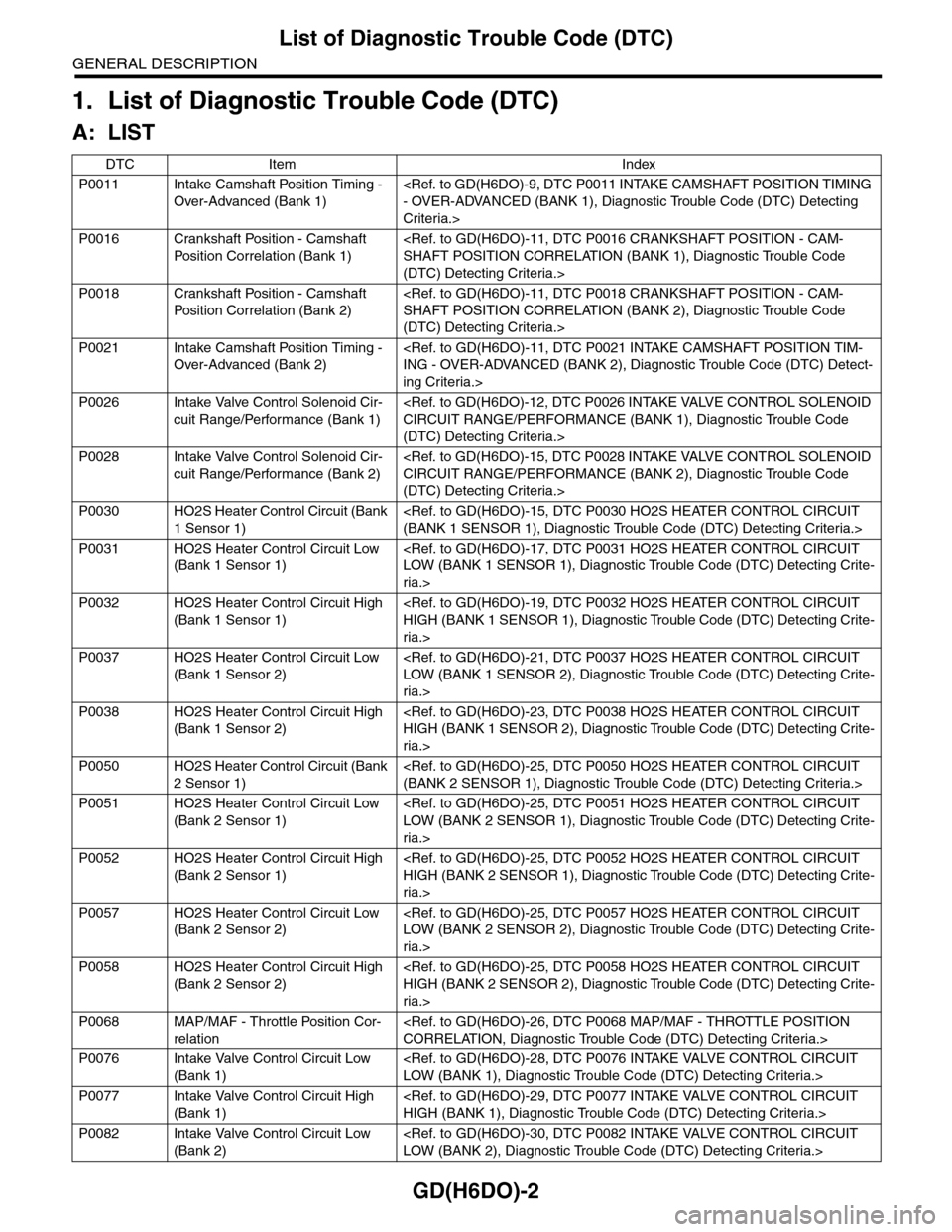
1. List of Diagnostic Trouble Code (DTC)
A: LIST
DTC Item Index
P0011 Intake Camshaft Position Timing -
Over-Advanced (Bank 1)
Criteria.>
P0016 Crankshaft Position - Camshaft
Pos it i o n C o r r el a ti o n ( B a nk 1)
(DTC) Detecting Criteria.>
P0018 Crankshaft Position - Camshaft
Pos it i o n C o r r el a ti o n ( B a nk 2)
(DTC) Detecting Criteria.>
P0021 Intake Camshaft Position Timing -
Over-Advanced (Bank 2)
ing Criteria.>
P0026 Intake Valve Control Solenoid Cir-
cuit Range/Performance (Bank 1)
(DTC) Detecting Criteria.>
P0028 Intake Valve Control Solenoid Cir-
cuit Range/Performance (Bank 2)
(DTC) Detecting Criteria.>
P0030 HO2S Heater Control Circuit (Bank
1 Sensor 1)
P0031 HO2S Heater Control Circuit Low
(Bank 1 Sensor 1)
ria.>
P0032 HO2S Heater Control Circuit High
(Bank 1 Sensor 1)
ria.>
P0037 HO2S Heater Control Circuit Low
(Bank 1 Sensor 2)
ria.>
P0038 HO2S Heater Control Circuit High
(Bank 1 Sensor 2)
ria.>
P0050 HO2S Heater Control Circuit (Bank
2 Sensor 1)
P0051 HO2S Heater Control Circuit Low
(Bank 2 Sensor 1)
ria.>
P0052 HO2S Heater Control Circuit High
(Bank 2 Sensor 1)
ria.>
P0057 HO2S Heater Control Circuit Low
(Bank 2 Sensor 2)
ria.>
P0058 HO2S Heater Control Circuit High
(Bank 2 Sensor 2)
ria.>
P0068 MAP/MAF - Throttle Position Cor-
relation
P0076 Intake Valve Control Circuit Low
(Bank 1)
P0077 Intake Valve Control Circuit High
(Bank 1)
P0082 Intake Valve Control Circuit Low
(Bank 2)
Page 1627 of 2453
GD(H6DO)-15
Diagnostic Trouble Code (DTC) Detecting Criteria
GENERAL DESCRIPTION
F: DTC P0028 INTAKE VALVE CONTROL SOLENOID CIRCUIT RANGE/PER-
FORMANCE (BANK 2)
NOTE:
For diagnostic procedures, refer to DTC P0026.
Criteria.>
G: DTC P0030 HO2S HEATER CONTROL CIRCUIT (BANK 1 SENSOR 1)
1. OUTLINE OF DIAGNOSIS
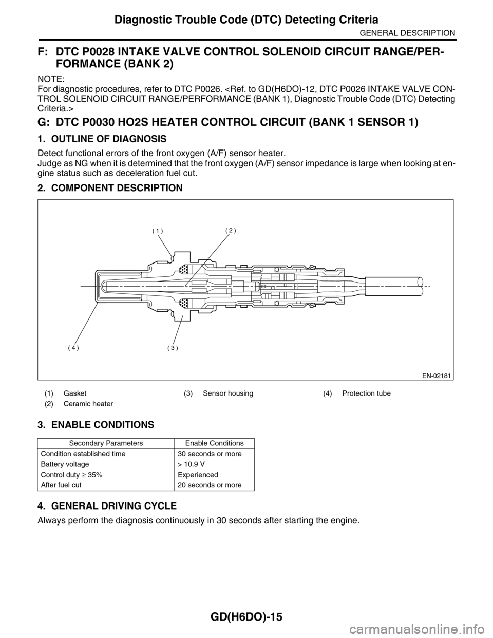
Detect functional errors of the front oxygen (A/F) sensor heater.
Judge as NG when it is determined that the front oxygen (A/F) sensor impedance is large when looking at en-
gine status such as deceleration fuel cut.
2. COMPONENT DESCRIPTION
3. ENABLE CONDITIONS
4. GENERAL DRIVING CYCLE
Always perform the diagnosis continuously in 30 seconds after starting the engine.
(1) Gasket (3) Sensor housing (4) Protection tube
(2) Ceramic heater
Secondary Parameters Enable Conditions
Condition established time 30 seconds or more
Battery voltage > 10.9 V
Control duty ≥ 35% Experienced
After fuel cut 20 seconds or more
EN-02181
( 1 )( 2 )
( 3 )( 4 )
Page 1629 of 2453
GD(H6DO)-17
Diagnostic Trouble Code (DTC) Detecting Criteria
GENERAL DESCRIPTION
H: DTC P0031 HO2S HEATER CONTROL CIRCUIT LOW (BANK 1 SENSOR 1)
1. OUTLINE OF DIAGNOSIS
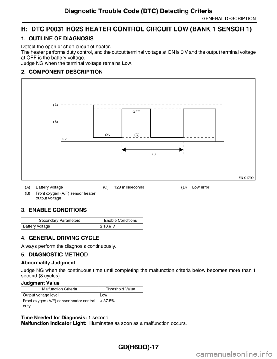
Detect the open or short circuit of heater.
The heater performs duty control, and the output terminal voltage at ON is 0 V and the output terminal voltage
at OFF is the battery voltage.
Judge NG when the terminal voltage remains Low.
2. COMPONENT DESCRIPTION
3. ENABLE CONDITIONS
4. GENERAL DRIVING CYCLE
Always perform the diagnosis continuously.
5. DIAGNOSTIC METHOD
Abnormality Judgment
Judge NG when the continuous time until completing the malfunction criteria below becomes more than 1
second (8 cycles).
Time Needed for Diagnosis: 1 second
Malfunction Indicator Light: Illuminates as soon as a malfunction occurs.
(A) Battery voltage (C) 128 milliseconds (D) Low error
(B) Front oxygen (A/F) sensor heater
output voltage
Secondary Parameters Enable Conditions
Battery voltage≥ 10.9 V
Judgment Value
Malfunction Criteria Threshold Value
Output voltage level Low
Fr o nt ox yg en (A / F ) se ns or h ea t er co n tr o l
duty
< 87.5%
EN-01792
(C)
(A)
(B)
ON
OFF
0V(D)
Page 1631 of 2453
GD(H6DO)-19
Diagnostic Trouble Code (DTC) Detecting Criteria
GENERAL DESCRIPTION
I: DTC P0032 HO2S HEATER CONTROL CIRCUIT HIGH (BANK 1 SENSOR 1)
1. OUTLINE OF DIAGNOSIS
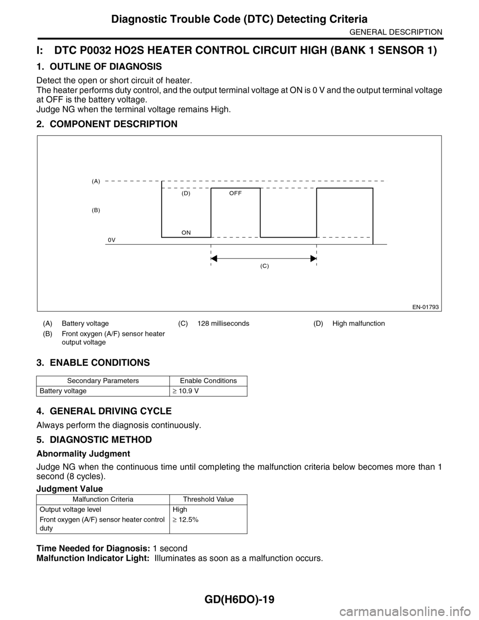
Detect the open or short circuit of heater.
The heater performs duty control, and the output terminal voltage at ON is 0 V and the output terminal voltage
at OFF is the battery voltage.
Judge NG when the terminal voltage remains High.
2. COMPONENT DESCRIPTION
3. ENABLE CONDITIONS
4. GENERAL DRIVING CYCLE
Always perform the diagnosis continuously.
5. DIAGNOSTIC METHOD
Abnormality Judgment
Judge NG when the continuous time until completing the malfunction criteria below becomes more than 1
second (8 cycles).
Time Needed for Diagnosis: 1 second
Malfunction Indicator Light: Illuminates as soon as a malfunction occurs.
(A) Battery voltage (C) 128 milliseconds (D) High malfunction
(B) Front oxygen (A/F) sensor heater
output voltage
Secondary Parameters Enable Conditions
Battery voltage≥ 10.9 V
Judgment Value
Malfunction Criteria Threshold Value
Output voltage level High
Fr o nt ox yg en (A / F ) se ns or h ea t er co n tr o l
duty
≥ 12.5%
EN-01793
(C)
(A)
(B)
ON
OFF
0V
(D)
Page 1633 of 2453

GD(H6DO)-21
Diagnostic Trouble Code (DTC) Detecting Criteria
GENERAL DESCRIPTION
J: DTC P0037 HO2S HEATER CONTROL CIRCUIT LOW (BANK 1 SENSOR 2)
1. OUTLINE OF DIAGNOSIS
Detect the rear oxygen sensor heater open or short circuit.
The rear oxygen sensor heater performs duty control, and the output terminal voltage at ON is 0 V, and the
output terminal voltage at OFF is the battery voltage.
Judge NG when the terminal voltage remains Low.
2. COMPONENT DESCRIPTION
3. ENABLE CONDITIONS
4. GENERAL DRIVING CYCLE
Perform the diagnosis continuously after starting the engine.
5. DIAGNOSTIC METHOD
Abnormality Judgment
Judge NG when the continuous time until completing all the malfunction criteria below becomes more than
2560 seconds.
Time Needed for Diagnosis: 2.56 second
Malfunction Indicator Light Illumination: Illuminates when malfunctions occur in 2 continuous driving cy-
cles.
(A) Battery voltage (C) 256 milliseconds (cycles) (D) Low error
(B) Rear oxygen (A/F) sensor heater
output voltage
Secondary Parameters Enable Conditions
Battery voltage > 10.9 V
Judgment Value
Malfunction Criteria Threshold Value
Output voltage level Low
Rear oxygen sensor heater control duty < 75%
EN-01792
(C)
(A)
(B)
ON
OFF
0V(D)
Page 1635 of 2453
GD(H6DO)-23
Diagnostic Trouble Code (DTC) Detecting Criteria
GENERAL DESCRIPTION
K: DTC P0038 HO2S HEATER CONTROL CIRCUIT HIGH (BANK 1 SENSOR 2)
1. OUTLINE OF DIAGNOSIS
Detect the rear oxygen sensor heater open or short circuit.
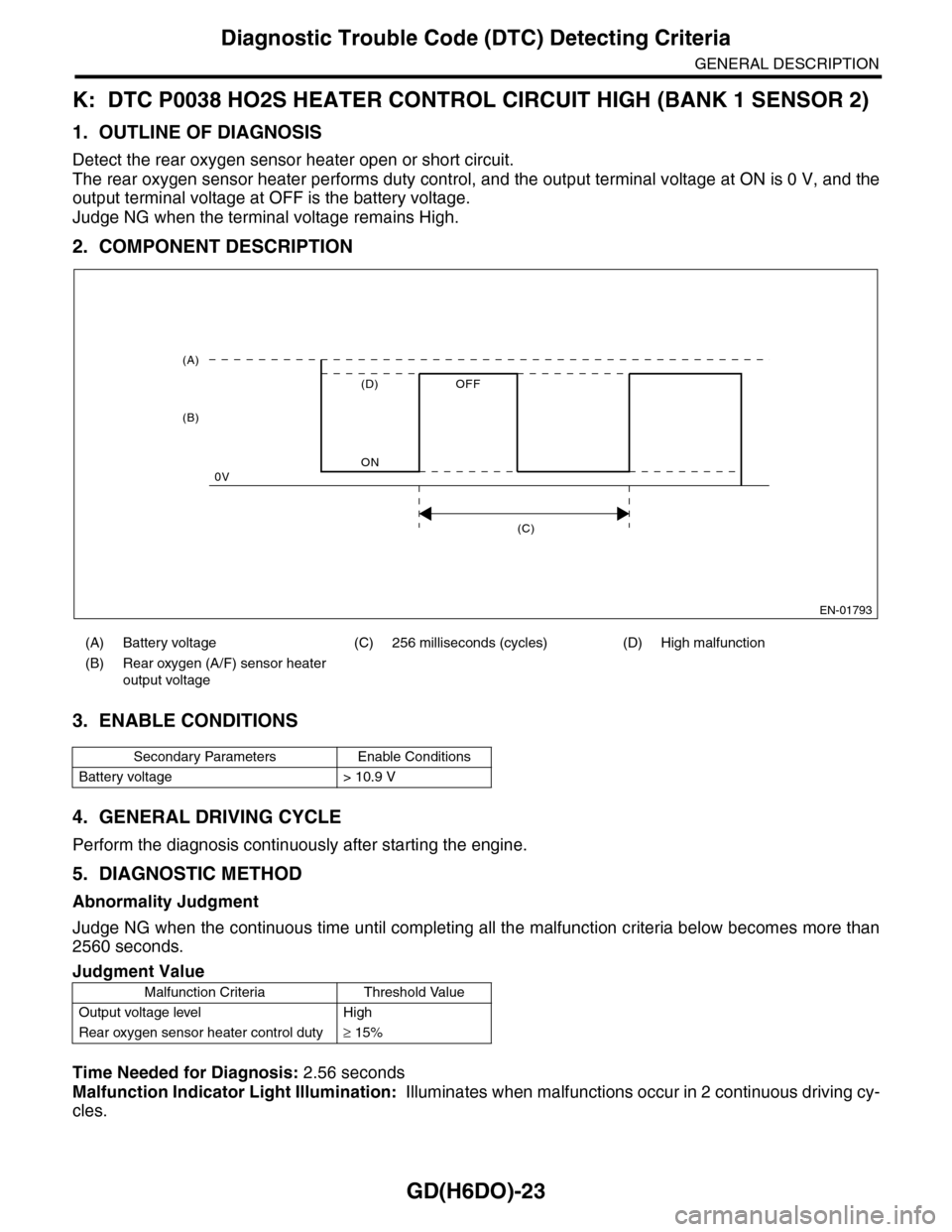
The rear oxygen sensor heater performs duty control, and the output terminal voltage at ON is 0 V, and the
output terminal voltage at OFF is the battery voltage.
Judge NG when the terminal voltage remains High.
2. COMPONENT DESCRIPTION
3. ENABLE CONDITIONS
4. GENERAL DRIVING CYCLE
Perform the diagnosis continuously after starting the engine.
5. DIAGNOSTIC METHOD
Abnormality Judgment
Judge NG when the continuous time until completing all the malfunction criteria below becomes more than
2560 seconds.
Time Needed for Diagnosis: 2.56 seconds
Malfunction Indicator Light Illumination: Illuminates when malfunctions occur in 2 continuous driving cy-
cles.
(A) Battery voltage (C) 256 milliseconds (cycles) (D) High malfunction
(B) Rear oxygen (A/F) sensor heater
output voltage
Secondary Parameters Enable Conditions
Battery voltage > 10.9 V
Judgment Value
Malfunction Criteria Threshold Value
Output voltage level High
Rear oxygen sensor heater control duty≥ 15%
EN-01793
(C)
(A)
(B)
ON
OFF
0V
(D)
Page 1637 of 2453
GD(H6DO)-25
Diagnostic Trouble Code (DTC) Detecting Criteria
GENERAL DESCRIPTION
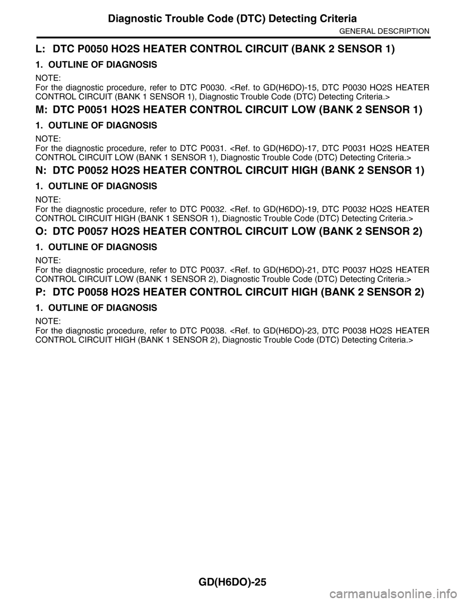
L: DTC P0050 HO2S HEATER CONTROL CIRCUIT (BANK 2 SENSOR 1)
1. OUTLINE OF DIAGNOSIS
NOTE:
For the diagnostic procedure, refer to DTC P0030.
M: DTC P0051 HO2S HEATER CONTROL CIRCUIT LOW (BANK 2 SENSOR 1)
1. OUTLINE OF DIAGNOSIS
NOTE:
For the diagnostic procedure, refer to DTC P0031.
N: DTC P0052 HO2S HEATER CONTROL CIRCUIT HIGH (BANK 2 SENSOR 1)
1. OUTLINE OF DIAGNOSIS
NOTE:
For the diagnostic procedure, refer to DTC P0032.
O: DTC P0057 HO2S HEATER CONTROL CIRCUIT LOW (BANK 2 SENSOR 2)
1. OUTLINE OF DIAGNOSIS
NOTE:
For the diagnostic procedure, refer to DTC P0037.
P: DTC P0058 HO2S HEATER CONTROL CIRCUIT HIGH (BANK 2 SENSOR 2)
1. OUTLINE OF DIAGNOSIS
NOTE:
For the diagnostic procedure, refer to DTC P0038.