Actuator SUBARU TRIBECA 2009 1.G Service Repair Manual
[x] Cancel search | Manufacturer: SUBARU, Model Year: 2009, Model line: TRIBECA, Model: SUBARU TRIBECA 2009 1.GPages: 2453, PDF Size: 46.32 MB
Page 1464 of 2453
EN(H6DO)(diag)-303
Diagnostic Procedure with Diagnostic Trouble Code (DTC)
ENGINE (DIAGNOSTICS)
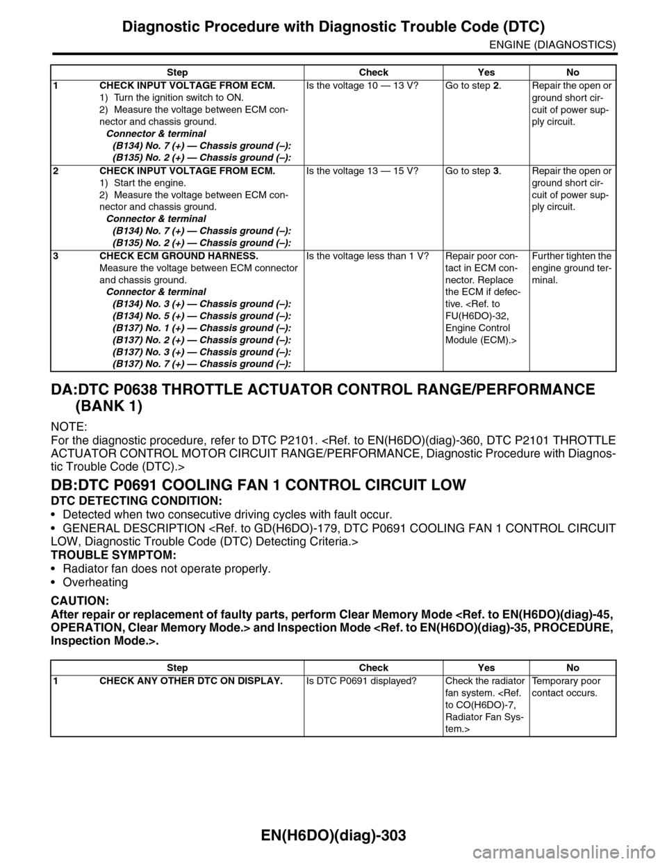
DA:DTC P0638 THROTTLE ACTUATOR CONTROL RANGE/PERFORMANCE
(BANK 1)
NOTE:
For the diagnostic procedure, refer to DTC P2101.
tic Trouble Code (DTC).>
DB:DTC P0691 COOLING FAN 1 CONTROL CIRCUIT LOW
DTC DETECTING CONDITION:
•Detected when two consecutive driving cycles with fault occur.
•GENERAL DESCRIPTION
TROUBLE SYMPTOM:
•Radiator fan does not operate properly.
•Overheating
CAUTION:
After repair or replacement of faulty parts, perform Clear Memory Mode
Step Check Yes No
1CHECK INPUT VOLTAGE FROM ECM.
1) Turn the ignition switch to ON.
2) Measure the voltage between ECM con-
nector and chassis ground.
Connector & terminal
(B134) No. 7 (+) — Chassis ground (–):
(B135) No. 2 (+) — Chassis ground (–):
Is the voltage 10 — 13 V? Go to step 2.Repair the open or
ground short cir-
cuit of power sup-
ply circuit.
2CHECK INPUT VOLTAGE FROM ECM.
1) Start the engine.
2) Measure the voltage between ECM con-
nector and chassis ground.
Connector & terminal
(B134) No. 7 (+) — Chassis ground (–):
(B135) No. 2 (+) — Chassis ground (–):
Is the voltage 13 — 15 V? Go to step 3.Repair the open or
ground short cir-
cuit of power sup-
ply circuit.
3CHECK ECM GROUND HARNESS.
Measure the voltage between ECM connector
and chassis ground.
Connector & terminal
(B134) No. 3 (+) — Chassis ground (–):
(B134) No. 5 (+) — Chassis ground (–):
(B137) No. 1 (+) — Chassis ground (–):
(B137) No. 2 (+) — Chassis ground (–):
(B137) No. 3 (+) — Chassis ground (–):
(B137) No. 7 (+) — Chassis ground (–):
Is the voltage less than 1 V? Repair poor con-
tact in ECM con-
nector. Replace
the ECM if defec-
tive.
Engine Control
Module (ECM).>
Fur ther tighten the
engine ground ter-
minal.
Step Check Yes No
1CHECK ANY OTHER DTC ON DISPLAY.Is DTC P0691 displayed? Check the radiator
fan system.
Radiator Fan Sys-
tem.>
Te m p o r a r y p o o r
contact occurs.
Page 1473 of 2453
EN(H6DO)(diag)-312
Diagnostic Procedure with Diagnostic Trouble Code (DTC)
ENGINE (DIAGNOSTICS)
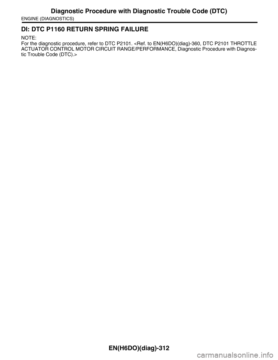
DI: DTC P1160 RETURN SPRING FAILURE
NOTE:
For the diagnostic procedure, refer to DTC P2101.
tic Trouble Code (DTC).>
Page 1521 of 2453
EN(H6DO)(diag)-360
Diagnostic Procedure with Diagnostic Trouble Code (DTC)
ENGINE (DIAGNOSTICS)
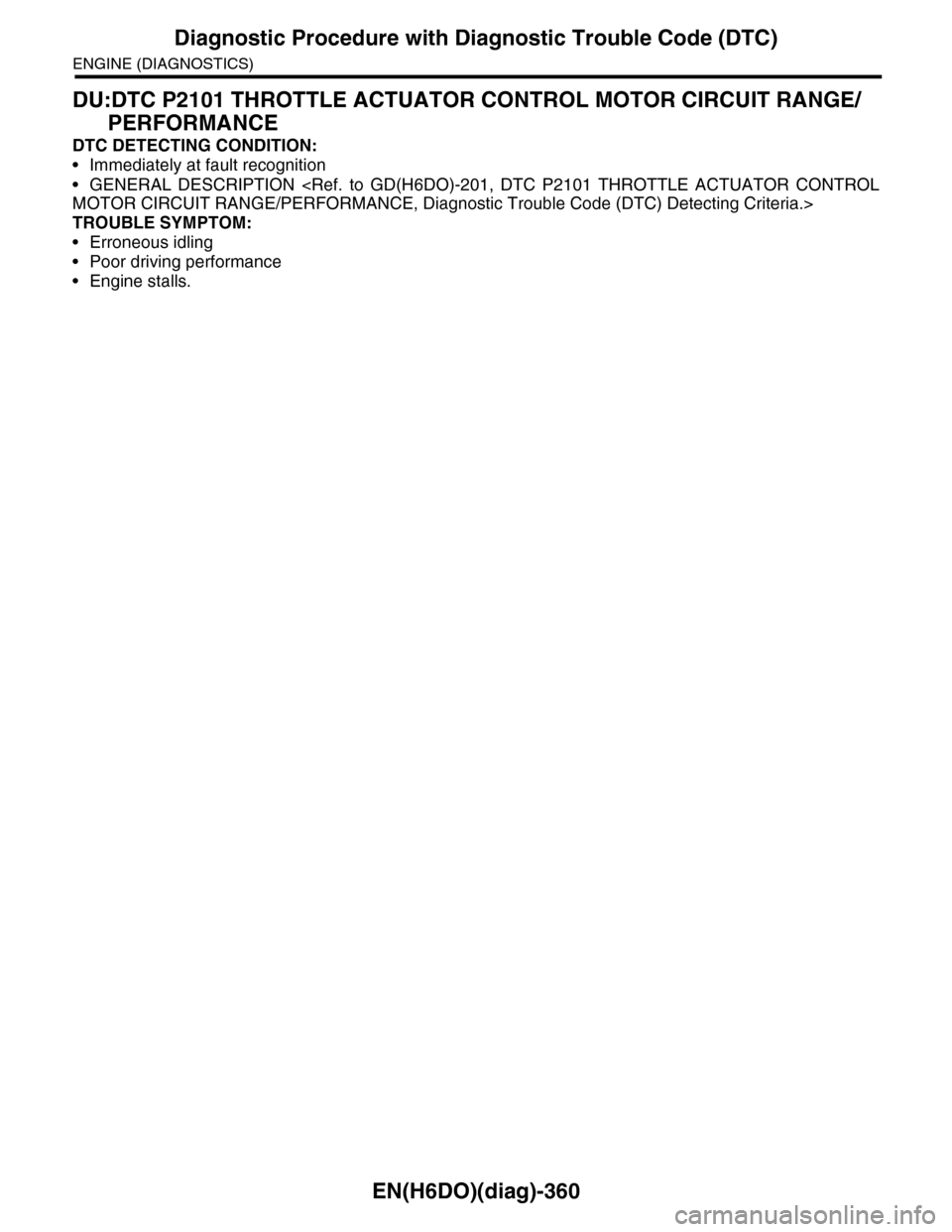
DU:DTC P2101 THROTTLE ACTUATOR CONTROL MOTOR CIRCUIT RANGE/
PERFORMANCE
DTC DETECTING CONDITION:
•Immediately at fault recognition
•GENERAL DESCRIPTION
TROUBLE SYMPTOM:
•Erroneous idling
•Poor driving performance
•Engine stalls.
Page 1528 of 2453
EN(H6DO)(diag)-367
Diagnostic Procedure with Diagnostic Trouble Code (DTC)
ENGINE (DIAGNOSTICS)
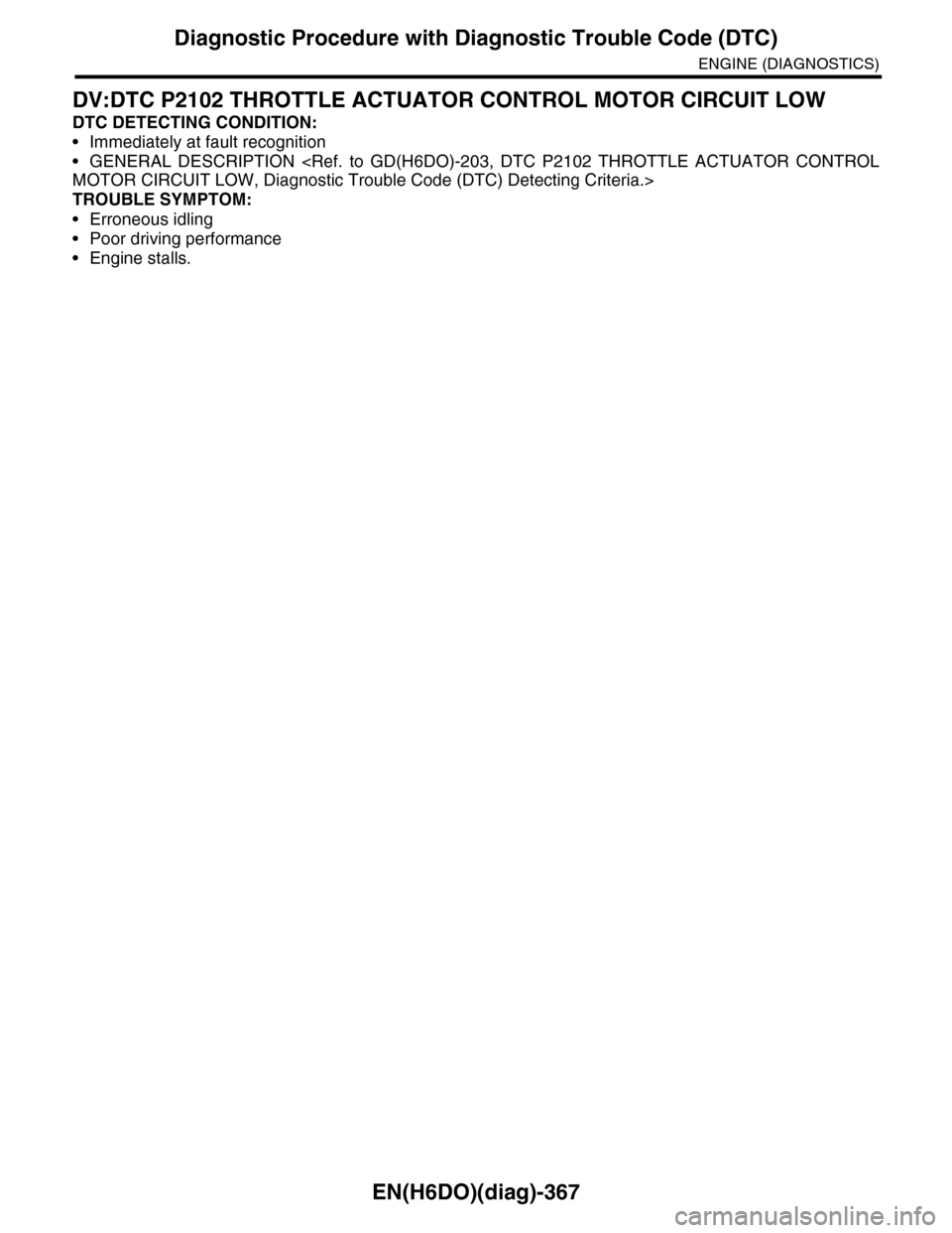
DV:DTC P2102 THROTTLE ACTUATOR CONTROL MOTOR CIRCUIT LOW
DTC DETECTING CONDITION:
•Immediately at fault recognition
•GENERAL DESCRIPTION
TROUBLE SYMPTOM:
•Erroneous idling
•Poor driving performance
•Engine stalls.
Page 1531 of 2453
EN(H6DO)(diag)-370
Diagnostic Procedure with Diagnostic Trouble Code (DTC)
ENGINE (DIAGNOSTICS)
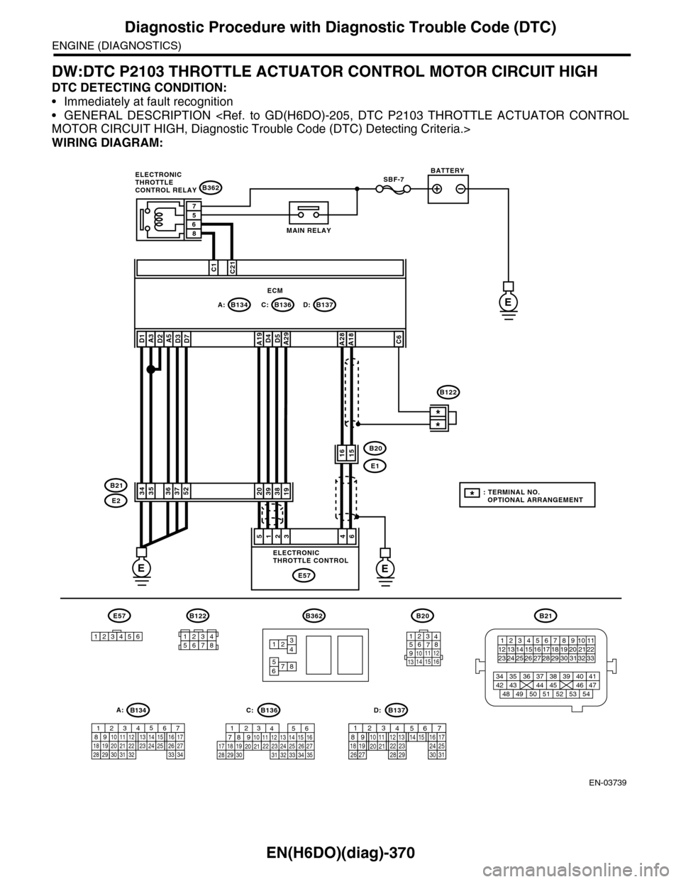
DW:DTC P2103 THROTTLE ACTUATOR CONTROL MOTOR CIRCUIT HIGH
DTC DETECTING CONDITION:
•Immediately at fault recognition
•GENERAL DESCRIPTION
WIRING DIAGRAM:
EN-03739
SBF-7
B134A:B137B136D:
B362
E1
B20
C:E
EE
C1C21
38392019
1615
*
*
E2
B21
E57
461235
D4D5A29A19A5D3D7A3D2D1
3536375234
A28A18C6
ECM
57
86
B362
12
78
34
56
B21
12345678910 1112 1314 1516 1718 1920 21222324 25
34 35 36 37 38 39 40 41
48 49 50 51 52 53 5442 43 44 45 46 47
26 2728 2930 313233
B122
12345678
1289563410 11 121920 2129 3031
13 14 15161727281822 2324 25 267
32 3334 35
B136C:
12789563410 11 121920 2129 30 31
13 14 151617
27 281822 23 24 2526
B137D:
BATTERY
MAIN RELAY
ELECTRONICTHROTTLECONTROL RELAY
ELECTRONICTHROTTLE CONTROL
B20
1234567891011 121314 15 16
E57
123456
B122
*: TERMINAL NO. OPTIONAL ARRANGEMENT
A:B134
85610 11 12 13 14 157213416
3019 20 2228 29
91718252123 24323126 2733 34
Page 1532 of 2453
EN(H6DO)(diag)-371
Diagnostic Procedure with Diagnostic Trouble Code (DTC)
ENGINE (DIAGNOSTICS)
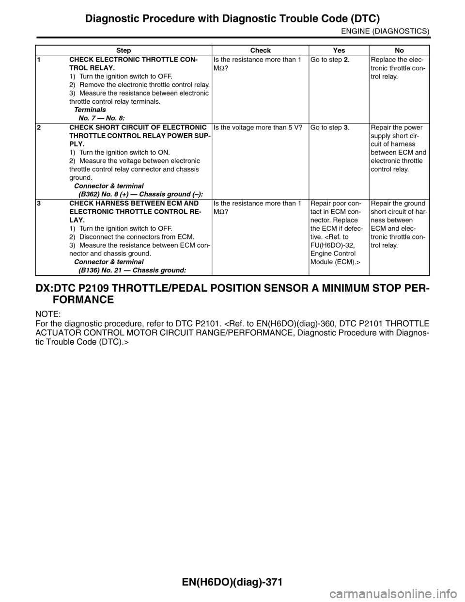
DX:DTC P2109 THROTTLE/PEDAL POSITION SENSOR A MINIMUM STOP PER-
FORMANCE
NOTE:
For the diagnostic procedure, refer to DTC P2101.
tic Trouble Code (DTC).>
Step Check Yes No
1CHECK ELECTRONIC THROTTLE CON-
TROL RELAY.
1) Turn the ignition switch to OFF.
2) Remove the electronic throttle control relay.
3) Measure the resistance between electronic
throttle control relay terminals.
Te r m i n a l s
No. 7 — No. 8:
Is the resistance more than 1
MΩ?
Go to step 2.Replace the elec-
tronic throttle con-
trol relay.
2 CHECK SHORT CIRCUIT OF ELECTRONIC
THROTTLE CONTROL RELAY POWER SUP-
PLY.
1) Turn the ignition switch to ON.
2) Measure the voltage between electronic
throttle control relay connector and chassis
ground.
Connector & terminal
(B362) No. 8 (+) — Chassis ground (–):
Is the voltage more than 5 V? Go to step 3.Repair the power
supply short cir-
cuit of harness
between ECM and
electronic throttle
control relay.
3CHECK HARNESS BETWEEN ECM AND
ELECTRONIC THROTTLE CONTROL RE-
LAY.
1) Turn the ignition switch to OFF.
2) Disconnect the connectors from ECM.
3) Measure the resistance between ECM con-
nector and chassis ground.
Connector & terminal
(B136) No. 21 — Chassis ground:
Is the resistance more than 1
MΩ?
Repair poor con-
tact in ECM con-
nector. Replace
the ECM if defec-
tive.
Engine Control
Module (ECM).>
Repair the ground
short circuit of har-
ness between
ECM and elec-
tronic throttle con-
trol relay.
Page 1618 of 2453
GD(H6DO)-6
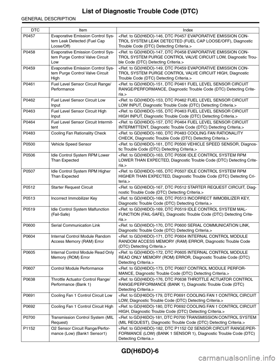
List of Diagnostic Trouble Code (DTC)
GENERAL DESCRIPTION
P0457 Evaporative Emission Control Sys-
tem Leak Detected (Fuel Cap
Loose/Off)
Tr o u b l e C o d e ( D T C ) D e t e c t i n g C r i t e r i a . >
P0458 Evaporative Emission Control Sys-
tem Purge Control Valve Circuit
Low
ble Code (DTC) Detecting Criteria.>
P0459 Evaporative Emission Control Sys-
tem Purge Control Valve Circuit
High
Tr o u b l e C o d e ( D T C ) D e t e c t i n g C r i t e r i a . >
P0461 Fuel Level Sensor Circuit Range/
Per fo r m an ce
ria.>
P0462 Fuel Level Sensor Circuit Low
Input
P0463 Fuel Level Sensor Circuit High
Input
P0464 Fuel Level Sensor Circuit Intermit-
tent
P0483 Cooling Fan Rationality Check
P0500 Vehicle Speed Sensor
P0506 Idle Control System RPM Lower
Than Expected
ria.>
P0507 Idle Control System RPM Higher
Than Expected
teria.>
P0512 Starter Request Circuit
P0513 Incorrect Immobilizer Key
P0519 Idle Control System Malfunction
(Fail-Safe)
ria.>
P0600 Serial Communication Link
P0604 Internal Control Module Random
Access Memory (RAM) Error
(DTC) Detecting Criteria.>
P0605 Internal Control Module Read Only
Memory (ROM) Error
Detecting Criteria.>
P0607 Control Module Performance
P0638 Throttle Actuator Control Range/
Per fo r m an ce ( B an k 1 )
Detecting Criteria.>
P0691 Cooling Fan 1 Control Circuit Low
P0692 Cooling Fan 1 Control Circuit High
P0700 Transmission Control System (MIL
Request)
P1152 O2 Sensor Circuit Range/Perfor-
mance (Low) (Bank1 Sensor1)
Detecting Criteria.>
DTC Item Index
Page 1620 of 2453
GD(H6DO)-8
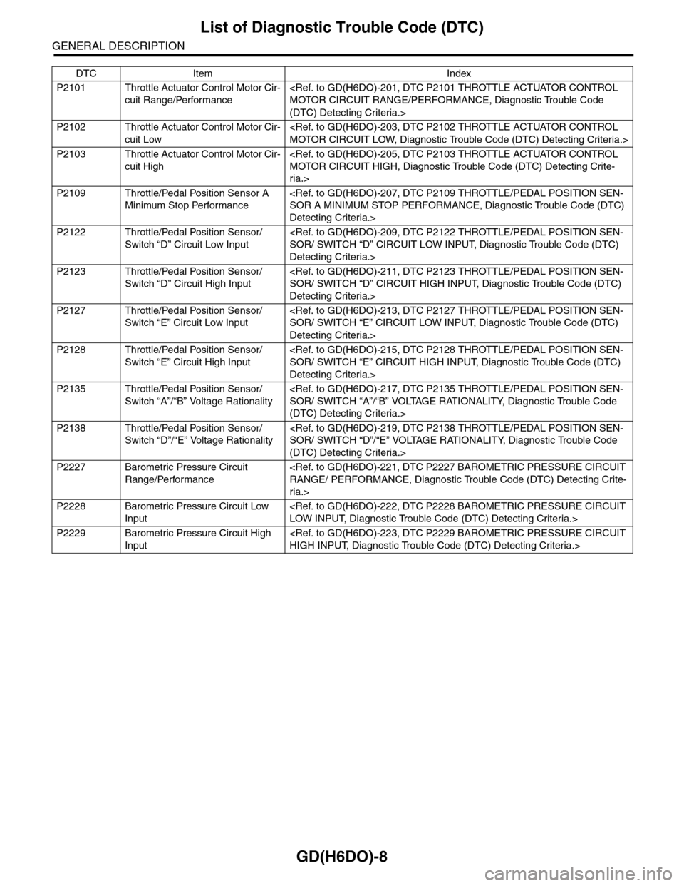
List of Diagnostic Trouble Code (DTC)
GENERAL DESCRIPTION
P2101 Throttle Actuator Control Motor Cir-
cuit Range/Performance
(DTC) Detecting Criteria.>
P2102 Throttle Actuator Control Motor Cir-
cuit Low
P2103 Throttle Actuator Control Motor Cir-
cuit High
ria.>
P2109 Throttle/Pedal Position Sensor A
Minimum Stop Performance
Detecting Criteria.>
P2122 Throttle/Pedal Position Sensor/
Switch “D” Circuit Low Input
Detecting Criteria.>
P2123 Throttle/Pedal Position Sensor/
Switch “D” Circuit High Input
Detecting Criteria.>
P2127 Throttle/Pedal Position Sensor/
Switch “E” Circuit Low Input
Detecting Criteria.>
P2128 Throttle/Pedal Position Sensor/
Switch “E” Circuit High Input
Detecting Criteria.>
P2135 Throttle/Pedal Position Sensor/
Switch “A”/“B” Voltage Rationality
(DTC) Detecting Criteria.>
P2138 Throttle/Pedal Position Sensor/
Switch “D”/“E” Voltage Rationality
(DTC) Detecting Criteria.>
P2227 Barometric Pressure Circuit
Range/Performance
ria.>
P2228 Barometric Pressure Circuit Low
Input
P2229 Barometric Pressure Circuit High
Input
DTC Item Index
Page 1788 of 2453
GD(H6DO)-176
Diagnostic Trouble Code (DTC) Detecting Criteria
GENERAL DESCRIPTION
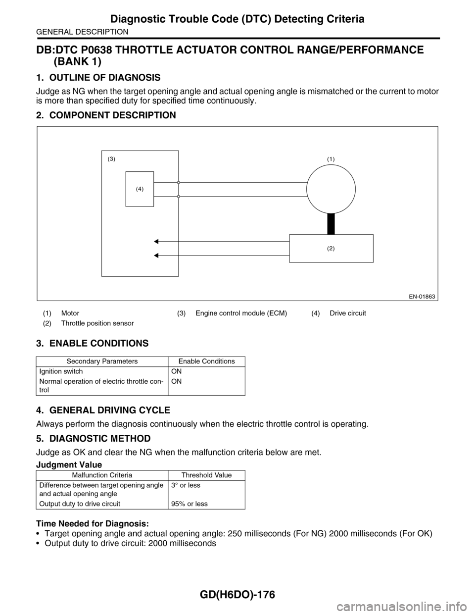
DB:DTC P0638 THROTTLE ACTUATOR CONTROL RANGE/PERFORMANCE
(BANK 1)
1. OUTLINE OF DIAGNOSIS
Judge as NG when the target opening angle and actual opening angle is mismatched or the current to motor
is more than specified duty for specified time continuously.
2. COMPONENT DESCRIPTION
3. ENABLE CONDITIONS
4. GENERAL DRIVING CYCLE
Always perform the diagnosis continuously when the electric throttle control is operating.
5. DIAGNOSTIC METHOD
Judge as OK and clear the NG when the malfunction criteria below are met.
Time Needed for Diagnosis:
•Target opening angle and actual opening angle: 250 milliseconds (For NG) 2000 milliseconds (For OK)
•Output duty to drive circuit: 2000 milliseconds
(1) Motor (3) Engine control module (ECM) (4) Drive circuit
(2) Throttle position sensor
Secondary Parameters Enable Conditions
Ignition switch ON
Normal operation of electric throttle con-
trol
ON
Judgment Value
Malfunction Criteria Threshold Value
Difference between target opening angle
and actual opening angle
3° or less
Output duty to drive circuit 95% or less
EN-01863
(3)
(4)
(1)
(2)
Page 1813 of 2453
GD(H6DO)-201
Diagnostic Trouble Code (DTC) Detecting Criteria
GENERAL DESCRIPTION
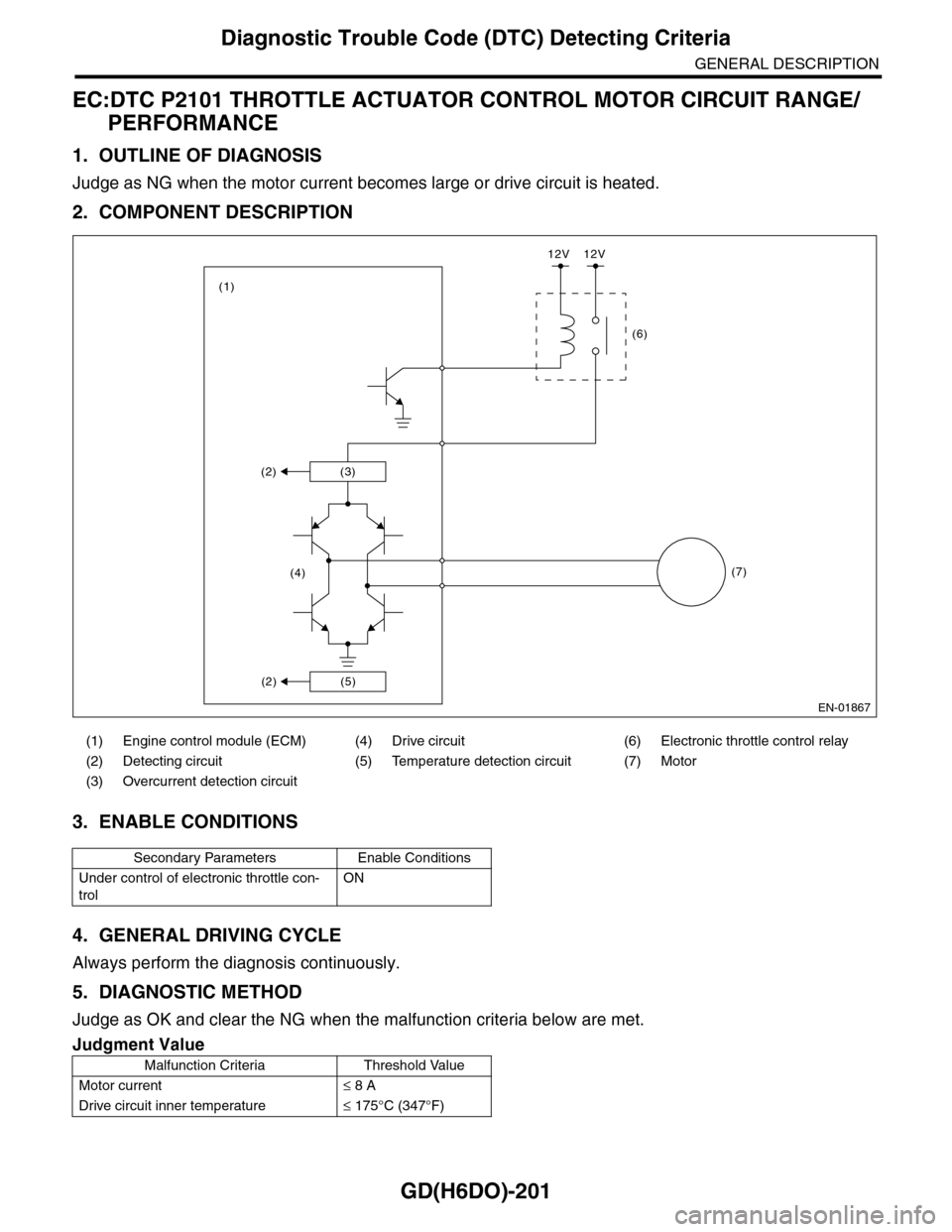
EC:DTC P2101 THROTTLE ACTUATOR CONTROL MOTOR CIRCUIT RANGE/
PERFORMANCE
1. OUTLINE OF DIAGNOSIS
Judge as NG when the motor current becomes large or drive circuit is heated.
2. COMPONENT DESCRIPTION
3. ENABLE CONDITIONS
4. GENERAL DRIVING CYCLE
Always perform the diagnosis continuously.
5. DIAGNOSTIC METHOD
Judge as OK and clear the NG when the malfunction criteria below are met.
(1) Engine control module (ECM) (4) Drive circuit (6) Electronic throttle control relay
(2) Detecting circuit (5) Temperature detection circuit (7) Motor
(3) Overcurrent detection circuit
Secondary Parameters Enable Conditions
Under control of electronic throttle con-
trol
ON
Judgment Value
Malfunction Criteria Threshold Value
Motor current≤ 8 A
Drive circuit inner temperature≤ 175°C (347°F)
EN-01867
(3)(2)
(5)(2)
(4)
(1)
(6)
(7)
12V 12V