check engine SUBARU TRIBECA 2009 1.G Service Repair Manual
[x] Cancel search | Manufacturer: SUBARU, Model Year: 2009, Model line: TRIBECA, Model: SUBARU TRIBECA 2009 1.GPages: 2453, PDF Size: 46.32 MB
Page 673 of 2453
SL-44
Front Hood Lock Assembly
SECURITY AND LOCKS
15.Front Hood Lock Assembly
A: REMOVAL
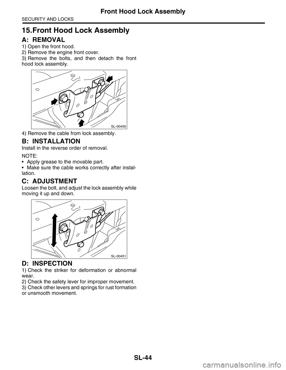
1) Open the front hood.
2) Remove the engine front cover.
3) Remove the bolts, and then detach the front
hood lock assembly.
4) Remove the cable from lock assembly.
B: INSTALLATION
Install in the reverse order of removal.
NOTE:
•Apply grease to the movable part.
•Make sure the cable works correctly after instal-
lation.
C: ADJUSTMENT
Loosen the bolt, and adjust the lock assembly while
moving it up and down.
D: INSPECTION
1) Check the striker for deformation or abnormal
wear.
2) Check the safety lever for improper movement.
3) Check other levers and springs for rust formation
or unsmooth movement.
SL-00450
SL-00451
Page 742 of 2453
BR-28
Brake Booster
BRAKE
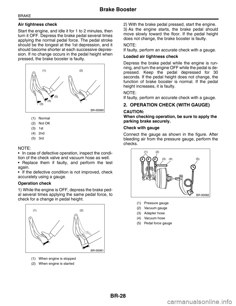
Air tightness check
Start the engine, and idle it for 1 to 2 minutes, then
turn it OFF. Depress the brake pedal several times
applying the normal pedal force. The pedal stroke
should be the longest at the 1st depression, and it
should become shorter at each successive depres-
sion. If no change occurs in the pedal height when
pressed, the brake booster is faulty.
NOTE:
•In case of defective operation, inspect the condi-
tion of the check valve and vacuum hose as well.
•Replace them if faulty, and perform the test
again.
•If the defective condition is not improved, check
accurately using a gauge.
Operation check
1) While the engine is OFF, depress the brake ped-
al several times applying the same pedal force, to
check for a change in pedal height.
2) With the brake pedal pressed, start the engine.
3) As the engine starts, the brake pedal should
move slowly toward the floor. If the pedal height
does not change, the brake booster is faulty.
NOTE:
If faulty, perform an accurate check with a gauge.
Loaded air tightness check
Depress the brake pedal while the engine is run-
ning, and turn the engine OFF while the pedal is de-
pressed. Keep the pedal depressed for 30
seconds. If the pedal height does not change, the
function of brake booster is normal. If the pedal
height increases, it is faulty.
NOTE:
If faulty, perform an accurate check with a gauge.
2. OPERATION CHECK (WITH GAUGE)
CAUTION:
When checking operation, be sure to apply the
parking brake securely.
Check with gauge
Connect the gauge as shown in the figure. After
bleeding air from the pressure gauge, perform the
checks.
(1) Normal
(2) Not OK
(3) 1st
(4) 2nd
(5) 3rd
(1) When engine is stopped
(2) When engine is started
(1)
(3)(4)
(5)
(2)
BR-00080
(1) (2)
BR-00081
(1) Pressure gauge
(2) Vacuum gauge
(3) Adapter hose
(4) Vacuum hose
(5) Pedal force gauge
(1) (2)
(3) (4) (5)
BR-00082
Page 743 of 2453
BR-29
Brake Booster
BRAKE
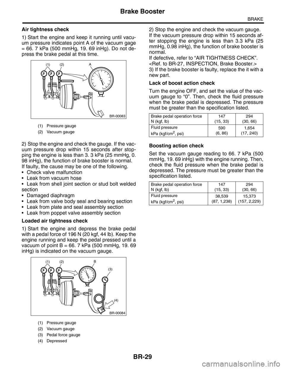
Air tightness check
1) Start the engine and keep it running until vacu-
um pressure indicates point A of the vacuum gage
= 66. 7 kPa (500 mmHg, 19. 69 inHg). Do not de-
press the brake pedal at this time.
2) Stop the engine and check the gauge. If the vac-
uum pressure drop within 15 seconds after stop-
ping the engine is less than 3. 3 kPa (25 mmHg, 0.
98 inHg), the function of brake booster is normal.
If faulty, the cause may be one of the following.
•Check valve malfunction
•Leak from vacuum hose
•Leak from shell joint section or stud bolt welded
section
•Damaged diaphragm
•Leak from valve body seal and bearing section
•Leak from plate and seal assembly section
•Leak from poppet valve assembly section
Loaded air tightness check
1) Start the engine and depress the brake pedal
with a pedal force of 196 N (20 kgf, 44 lb). Keep the
engine running and keep the pedal pressed until a
vacuum of point B = 66. 7 kPa (500 mmHg, 19. 69
inHg) is indicated on the vacuum gauge.
2) Stop the engine and check the vacuum gauge.
If the vacuum pressure drop within 15 seconds af-
ter stopping the engine is less than 3.3 kPa (25
mmHg, 0.98 inHg), the function of brake booster is
normal.
If defective, refer to “AIR TIGHTNESS CHECK”.
3) If the brake booster is faulty, replace the it with a
new part.
Lack of boost action check
Turn the engine OFF, and set the value of the vac-
uum gauge to “0”. Then, check the fluid pressure
when the brake pedal is depressed. The pressure
must be greater than the specification listed.
Boosting action check
Set the vacuum gauge reading to 66. 7 kPa (500
mmHg, 19. 69 inHg) with the engine running. Then,
check the fluid pressure when the brake pedal is
depressed. The pressure must be greater than the
specification listed.
(1) Pressure gauge
(2) Vacuum gauge
(1) Pressure gauge
(2) Vacuum gauge
(3) Pedal force gauge
(4) Depressed
(1) (2)A
BR-00083
B(1) (2)
(3)
(4)
BR-00084
Brake pedal operation force
N (kgf, lb)
147
(15, 33)
294
(30, 66)
Fluid pressure
kPa (kgf/cm2, psi)
590
(6, 86)
1,654
(17, 240)
Brake pedal operation force
N (kgf, lb)
147
(15, 33)
294
(30, 66)
Fluid pressure
kPa (kgf/cm2, psi)
38,539
(87, 1,238)
15,373
(157, 2,229)
Page 746 of 2453
BR-32
Air Bleeding
BRAKE
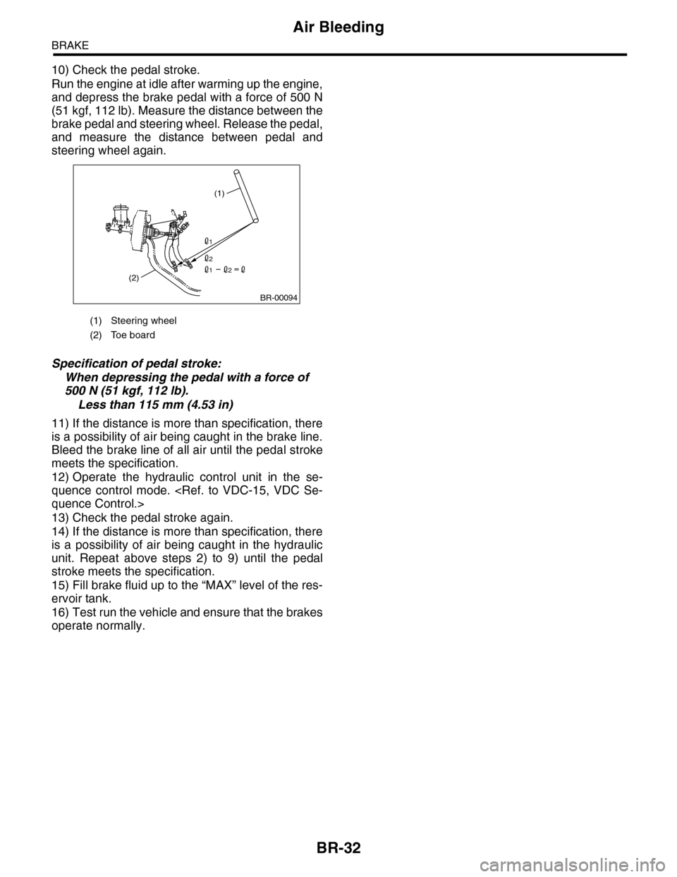
10) Check the pedal stroke.
Run the engine at idle after warming up the engine,
and depress the brake pedal with a force of 500 N
(51 kgf, 112 lb). Measure the distance between the
brake pedal and steering wheel. Release the pedal,
and measure the distance between pedal and
steering wheel again.
Specification of pedal stroke:
When depressing the pedal with a force of
500 N (51 kgf, 112 lb).
Less than 115 mm (4.53 in)
11) If the distance is more than specification, there
is a possibility of air being caught in the brake line.
Bleed the brake line of all air until the pedal stroke
meets the specification.
12) Operate the hydraulic control unit in the se-
quence control mode.
13) Check the pedal stroke again.
14) If the distance is more than specification, there
is a possibility of air being caught in the hydraulic
unit. Repeat above steps 2) to 9) until the pedal
stroke meets the specification.
15) Fill brake fluid up to the “MAX” level of the res-
ervoir tank.
16) Test run the vehicle and ensure that the brakes
operate normally.
(1) Steering wheel
(2) Toe board
(1)
(2)
BR-00094
1
2
21
Page 753 of 2453
BR-39
Brake Vacuum Pump
BRAKE
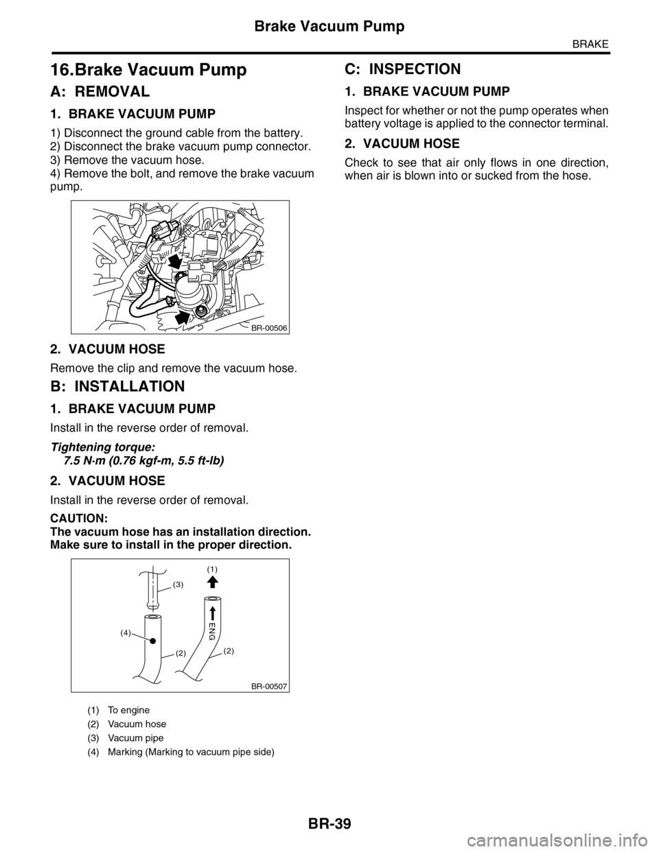
16.Brake Vacuum Pump
A: REMOVAL
1. BRAKE VACUUM PUMP
1) Disconnect the ground cable from the battery.
2) Disconnect the brake vacuum pump connector.
3) Remove the vacuum hose.
4) Remove the bolt, and remove the brake vacuum
pump.
2. VACUUM HOSE
Remove the clip and remove the vacuum hose.
B: INSTALLATION
1. BRAKE VACUUM PUMP
Install in the reverse order of removal.
Tightening torque:
7.5 N·m (0.76 kgf-m, 5.5 ft-lb)
2. VACUUM HOSE
Install in the reverse order of removal.
CAUTION:
The vacuum hose has an installation direction.
Make sure to install in the proper direction.
C: INSPECTION
1. BRAKE VACUUM PUMP
Inspect for whether or not the pump operates when
battery voltage is applied to the connector terminal.
2. VACUUM HOSE
Check to see that air only flows in one direction,
when air is blown into or sucked from the hose.
(1) To engine
(2) Vacuum hose
(3) Vacuum pipe
(4) Marking (Marking to vacuum pipe side)
BR-00506
BR-00507
(1)
(2)(2)
(4)
(3)
ENG
Page 757 of 2453
BVC(diag)-2
Basic Diagnostic Procedure
BRAKE VACUUM CONTROL (BVC) (DIAGNOSTICS)
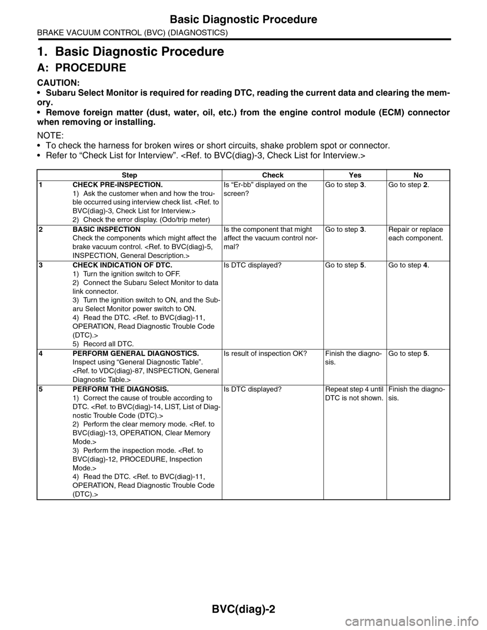
1. Basic Diagnostic Procedure
A: PROCEDURE
CAUTION:
•Subaru Select Monitor is required for reading DTC, reading the current data and clearing the mem-
ory.
•Remove foreign matter (dust, water, oil, etc.) from the engine control module (ECM) connector
when removing or installing.
NOTE:
•To check the harness for broken wires or short circuits, shake problem spot or connector.
•Refer to “Check List for Interview”.
Step Check Yes No
1CHECK PRE-INSPECTION.
1) Ask the customer when and how the trou-
ble occurred using interview check list.
2) Check the error display. (Odo/trip meter)
Is “Er-bb” displayed on the
screen?
Go to step 3.Go to step 2.
2BASIC INSPECTION
Check the components which might affect the
brake vacuum control.
Is the component that might
affect the vacuum control nor-
mal?
Go to step 3.Repair or replace
each component.
3CHECK INDICATION OF DTC.
1) Turn the ignition switch to OFF.
2) Connect the Subaru Select Monitor to data
link connector.
3) Turn the ignition switch to ON, and the Sub-
aru Select Monitor power switch to ON.
4) Read the DTC.
(DTC).>
5) Record all DTC.
Is DTC displayed? Go to step 5.Go to step 4.
4PERFORM GENERAL DIAGNOSTICS.
Inspect using “General Diagnostic Table”.
Is result of inspection OK? Finish the diagno-
sis.
Go to step 5.
5PERFORM THE DIAGNOSIS.
1) Correct the cause of trouble according to
DTC.
2) Perform the clear memory mode.
Mode.>
3) Perform the inspection mode.
Mode.>
4) Read the DTC.
(DTC).>
Is DTC displayed? Repeat step 4 until
DTC is not shown.
Finish the diagno-
sis.
Page 758 of 2453
BVC(diag)-3
Check List for Interview
BRAKE VACUUM CONTROL (BVC) (DIAGNOSTICS)
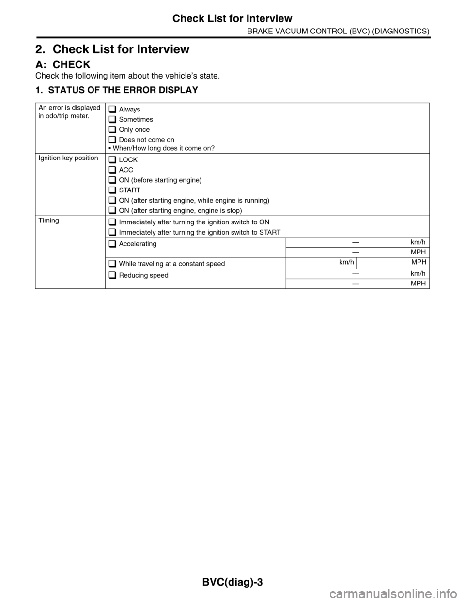
2. Check List for Interview
A: CHECK
Check the following item about the vehicle’s state.
1. STATUS OF THE ERROR DISPLAY
An error is displayed
in odo/trip meter. Always
Sometimes
Only once
Does not come on
• When/How long does it come on?
Ignition key position LOCK
ACC
ON (before starting engine)
START
ON (after starting engine, while engine is running)
ON (after starting engine, engine is stop)
Timing Immediately after turning the ignition switch to ON
Immediately after turning the ignition switch to START
Accelerating — km/h
— MPH
While traveling at a constant speedkm/h MPH
Reducing speed — km/h
— MPH
Page 759 of 2453
BVC(diag)-4
Check List for Interview
BRAKE VACUUM CONTROL (BVC) (DIAGNOSTICS)
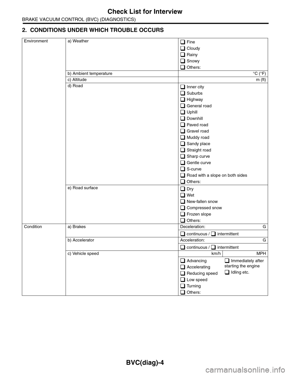
2. CONDITIONS UNDER WHICH TROUBLE OCCURS
Environment a) Weather Fine
Cloudy
Rainy
Snowy
Others:
b) Ambient temperature°C (°F)
c) Altitudem (ft)
d) Road Inner city
Suburbs
Highway
General road
Uphill
Downhill
Paved road
Gravel road
Muddy road
Sandy place
Straight road
Sharp cur ve
Gentle curve
S-curve
Road with a slope on both sides
Others:
e) Road surface Dr y
Wet
New-fallen snow
Compressed snow
Frozen slope
Others:
Condition a) Brakes Deceleration: G
continuous / intermittent
b) Accelerator Acceleration: G
continuous / intermittent
c) Vehicle speed km/h MPH
Advancing
Accelerating
Reducing speed
Low speed
Turning
Others:
Immediately after
starting the engine
Idling etc.
Page 764 of 2453
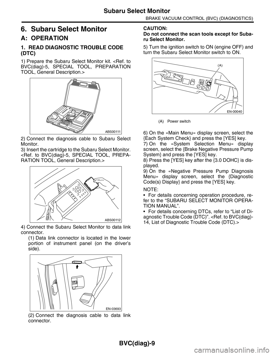
BVC(diag)-9
Subaru Select Monitor
BRAKE VACUUM CONTROL (BVC) (DIAGNOSTICS)
6. Subaru Select Monitor
A: OPERATION
1. READ DIAGNOSTIC TROUBLE CODE
(DTC)
1) Prepare the Subaru Select Monitor kit.
TOOL, General Description.>
2) Connect the diagnosis cable to Subaru Select
Monitor.
3) Insert the cartridge to the Subaru Select Monitor.
4) Connect the Subaru Select Monitor to data link
connector.
(1) Data link connector is located in the lower
portion of instrument panel (on the driver’s
side).
(2) Connect the diagnosis cable to data link
connector.
CAUTION:
Do not connect the scan tools except for Suba-
ru Select Monitor.
5) Turn the ignition switch to ON (engine OFF) and
turn the Subaru Select Monitor switch to ON.
6) On the «Main Menu» display screen, select the
{Each System Check} and press the [YES] key.
7) On the «System Selection Menu» display
screen, select the {Brake Negative Pressure Pump
System} and press the [YES] key.
8) Press the [YES] key after the {3.0 DOHC} is dis-
played.
9) On the «Negative Pressure Pump Diagnosis
Menu» display screen, select the {Diagnostic
Code(s) Display} and press the [YES] key.
NOTE:
•For details concerning operation procedure, re-
fer to the “SUBARU SELECT MONITOR OPERA-
TION MANUAL”.
•For details concerning DTCs, refer to “List of Di-
agnostic Trouble Code (DTC)”.
ABS00111
ABS00112
EN-03693
(A) Power switch
(A)
EN-00040
Page 765 of 2453
![SUBARU TRIBECA 2009 1.G Service Repair Manual BVC(diag)-10
Subaru Select Monitor
BRAKE VACUUM CONTROL (BVC) (DIAGNOSTICS)
2. READ CURRENT DATA
1) On the «Main Menu» display screen, select the {Each System Check} and press the [YES] key.
2) On t SUBARU TRIBECA 2009 1.G Service Repair Manual BVC(diag)-10
Subaru Select Monitor
BRAKE VACUUM CONTROL (BVC) (DIAGNOSTICS)
2. READ CURRENT DATA
1) On the «Main Menu» display screen, select the {Each System Check} and press the [YES] key.
2) On t](/img/17/7322/w960_7322-764.png)
BVC(diag)-10
Subaru Select Monitor
BRAKE VACUUM CONTROL (BVC) (DIAGNOSTICS)
2. READ CURRENT DATA
1) On the «Main Menu» display screen, select the {Each System Check} and press the [YES] key.
2) On the «System Selection Menu» display screen, select the {Brake Negative Pressure Pump System} and
press the [YES] key.
3) Press the [YES] key after the {3.0 DOHC} is displayed.
4) On the «Negative Pressure Diagnosis Menu» display screen, select the {Current Data Display/Save}, and
then press the [YES] key.
5) On the «Data Display Menu» screen, select the {Data Display} and press the [YES] key.
6) Using a scroll key, scroll the display screen up or down until necessary data is shown.
•A list of the support data is shown in the following table.
NOTE:
For details concerning operation procedure, refer to the “SUBARU SELECT MONITOR OPERATION MAN-
UAL”.
3. CLEAR MEMORY MODE
1) On the «Main Menu» display screen, select the
{Each System Check} and press the [YES] key.
2) On the «System Selection Menu» display
screen, select the {Brake Negative Pressure Pump
System} and press the [YES] key.
3) Press the [YES] key after the {3.0 DOHC} is dis-
played.
4) On the «Negative Pressure Pump Diagnosis
Menu» display screen, select the {Clear Memory}
and press the [YES] key.
5) When “Done” and “Turn ignition switch OFF” are
shown on the display screen, turn the Subaru Se-
lect Monitor and ignition switch to OFF.
NOTE:
For details concerning operation procedure, refer
to the “SUBARU SELECT MONITOR OPERATION
MANUAL”.
4. FUNCTION CHECK MODE
1) Connect the test mode connector located under
the glove box.
2) Turn the ignition switch to ON (engine OFF) and
turn the Subaru Select Monitor switch to ON.
3) On the «Main Menu» display screen, select the
{Each System Check} and press the [YES] key.
4) On the «System Selection Menu» display
screen, select the {Brake Negative Pressure Pump
System} and press the [YES] key.
5) Press the [YES] key after the {3.0 DOHC} is dis-
played.
6) On the «Negative Pressure Pump Diagnosis
Menu» display screen, select the {Function Check
Mode} and press the [YES] key.
7) When the “Start Function Check Mode” is shown
on the screen, press the [YES] key.
8) When the “Depress the Brake Pedal 5 Times” is
shown on the screen, depress the brake pedal 5
times, and press the [YES] key while brake pedal is
not depressed.
9) Press the [YES] key after the {OK} is displayed.
Display Contents to be monitored Unit of measure
Atmospheric pressure Atmospheric pressure is displayed. mmHg, kPa or psig
Brake booster pressure Brake booster pressure is displayed. mmHg, kPa or psig
Te s t m o d e t e r m i n a l Te s t m o d e t e r m i n a l c o n n e c t i o n s t a t u s i s d i s p l a y e d . D C h e c k o r U C h e c k
Negative pressure pump motor Negative pressure motor operating status is displayed. ON or OFF
Negative pressure pump motor relay Negative pressure pump motor relay operating status is displayed. ON or OFF
Display Contents to be monitored
Clear Memory? DTC deleting function
(A) Test mode connector
EN-03694
(4)