diagram SUBARU TRIBECA 2009 1.G Service Repair Manual
[x] Cancel search | Manufacturer: SUBARU, Model Year: 2009, Model line: TRIBECA, Model: SUBARU TRIBECA 2009 1.GPages: 2453, PDF Size: 46.32 MB
Page 408 of 2453
AC(diag)-31
Diagnostic Procedure for Sensors
HVAC SYSTEM (AUTO A/C) (DIAGNOSTICS)
8. Diagnostic Procedure for Sensors
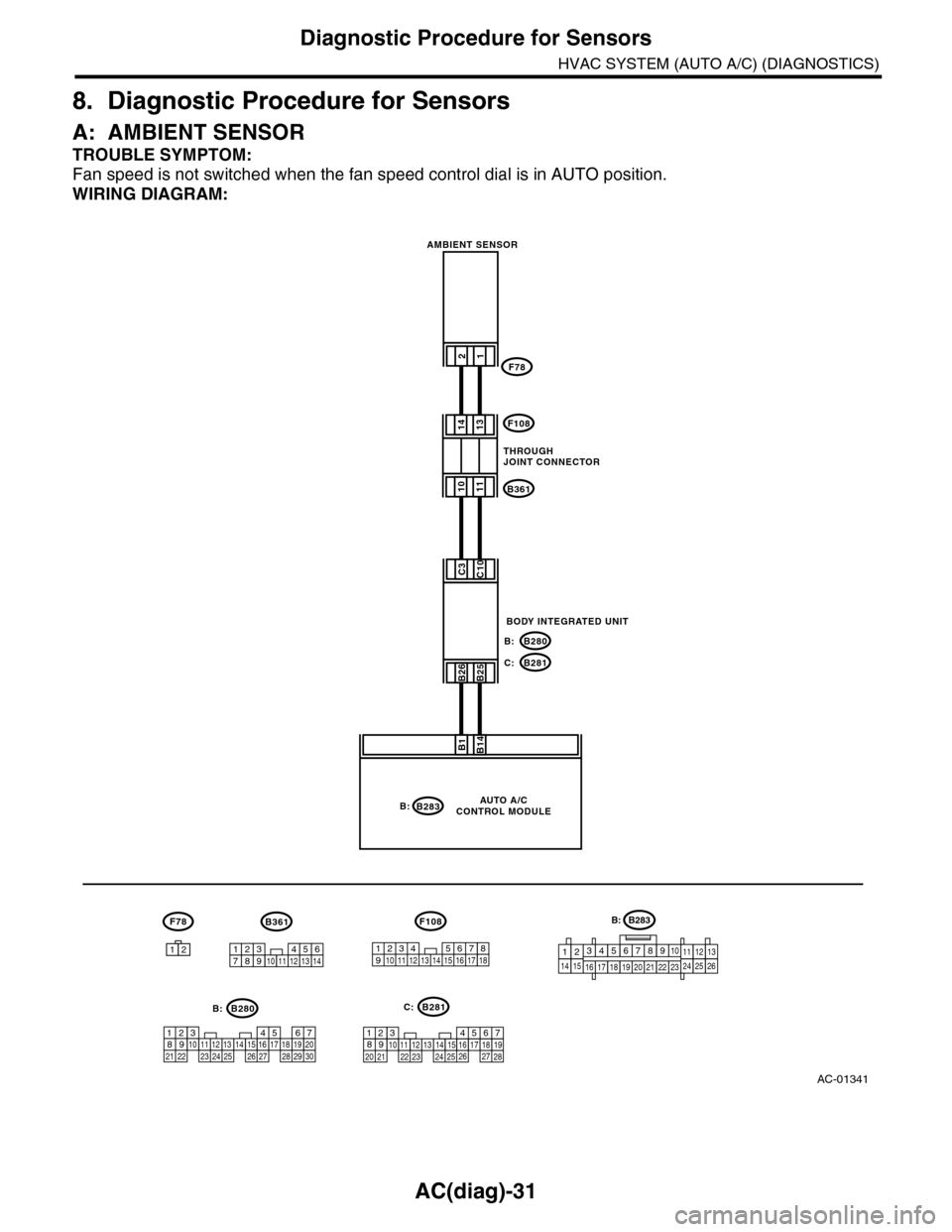
A: AMBIENT SENSOR
TROUBLE SYMPTOM:
Fan speed is not switched when the fan speed control dial is in AUTO position.
WIRING DIAGRAM:
AC-01341
B283
F78
B1B14
B:
21
F78
12
1011
1413
B26B25
C3C10
F108
B361
B280
B281
B:
C:
5467821931022 23111213141524 25 26 2716171828 29192021 30
B280B:B281
567821943102422 2325111213141526 27281617181920 21
C:
1234567891011121314
B361
123 8910411 12 13 14 15 165671718
F108
AUTO A/CCONTROL MODULE
AMBIENT SENSOR
BODY INTEGRATED UNIT
THROUGH JOINT CONNECTOR
B283B:
1234567891014151617181920212223111213242526
Page 410 of 2453
AC(diag)-33
Diagnostic Procedure for Sensors
HVAC SYSTEM (AUTO A/C) (DIAGNOSTICS)
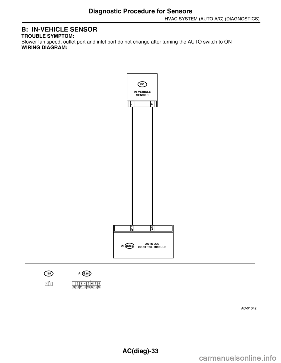
B: IN-VEHICLE SENSOR
TROUBLE SYMPTOM:
Blower fan speed, outlet port and inlet port do not change after turning the AUTO switch to ON
WIRING DIAGRAM:
AC-01342
A:B282
12345678910 11 12 13 14 15 16
i55
A:B282
A15A5
21
i55
12
AUTO A/CCONTROL MODULE
IN-VEHICLESENSOR
Page 412 of 2453
AC(diag)-35
Diagnostic Procedure for Sensors
HVAC SYSTEM (AUTO A/C) (DIAGNOSTICS)
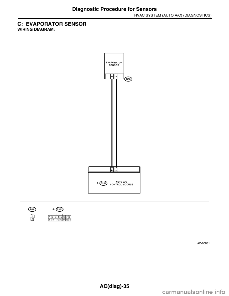
C: EVAPORATOR SENSOR
WIRING DIAGRAM:
AC-00831
A13A15
B8812
EVAPORATORSENSOR
B88
B282A:AUTO A/CCONTROL MODULE
12123412 891011 12 13 14 15 16567
B282A:
Page 414 of 2453
AC(diag)-37
Diagnostic Procedure for Sensors
HVAC SYSTEM (AUTO A/C) (DIAGNOSTICS)
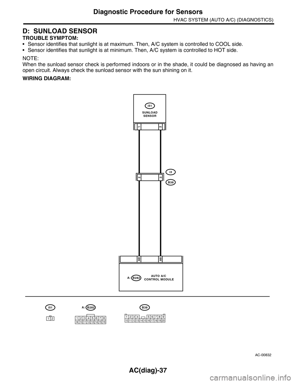
D: SUNLOAD SENSOR
TROUBLE SYMPTOM:
•Sensor identifies that sunlight is at maximum. Then, A/C system is controlled to COOL side.
•Sensor identifies that sunlight is at minimum. Then, A/C system is controlled to HOT side.
NOTE:
When the sunload sensor check is performed indoors or in the shade, it could be diagnosed as having an
open circuit. Always check the sunload sensor with the sun shining on it.
WIRING DIAGRAM:
AC-00832
A:B282
12345678910 11 12 13 14 15 16
i51
A:B282
A8A6
21
i3
B38
i51
12
AUTO A/C CONTROL MODULE
32
1234 5678910 11 12 13 14 15 16 17 18 19 20
B38
SUNLOADSENSOR
Page 422 of 2453

IM (diag)-6
Immobilizer Control Module I/O Signal
IMMOBILIZER (DIAGNOSTICS)
4. Immobilizer Control Module I/O
Signal
A: WIRING DIAGRAM
1. IMMOBILIZER
Page 426 of 2453
IM (diag)-10
Diagnostics Chart for Security Indicator Light
IMMOBILIZER (DIAGNOSTICS)
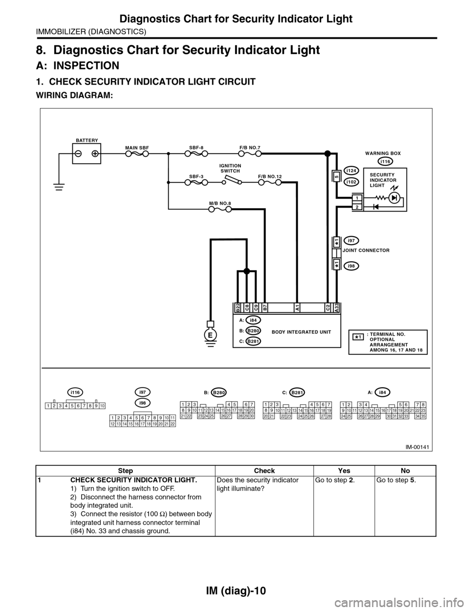
8. Diagnostics Chart for Security Indicator Light
A: INSPECTION
1. CHECK SECURITY INDICATOR LIGHT CIRCUIT
WIRING DIAGRAM:
IM-00141
MAIN SBF
SBF-3
BATTERY
WARNING BOX
BODY INTEGRATED UNIT
i116
F/B NO.7
F/B NO.12
IGNITIONSWITCH
A33C2B7C9C8
2
1
E
A1
M/B NO.8
SBF-8
B22
i84A:
B280B:
B281C:
567821943102422 23 25111213141526 27281617181920 21
B281i84
1234567891011121314151617181920212223242526272829303132333435
5467821931022 231112131415242526 2716171828 29192021 30
B280A:C:B:
5i124
i102
i97
i98
SECURITYINDICATORLIGHT
JOINT CONNECTOR
i116
12345678910i98
i97
12345678910111213141516171819202122
: TERMINAL NO. OPTIONAL ARRANGEMENT AMONG 16, 17 AND 18
1*
1*
1*
Step Check Yes No
1CHECK SECURITY INDICATOR LIGHT.
1) Turn the ignition switch to OFF.
2) Disconnect the harness connector from
body integrated unit.
3) Connect the resistor (100 Ω) between body
integrated unit harness connector terminal
(i84) No. 33 and chassis ground.
Does the security indicator
light illuminate?
Go to step 2.Go to step 5.
Page 428 of 2453
IM (diag)-12
Diagnostics Chart for Security Indicator Light
IMMOBILIZER (DIAGNOSTICS)
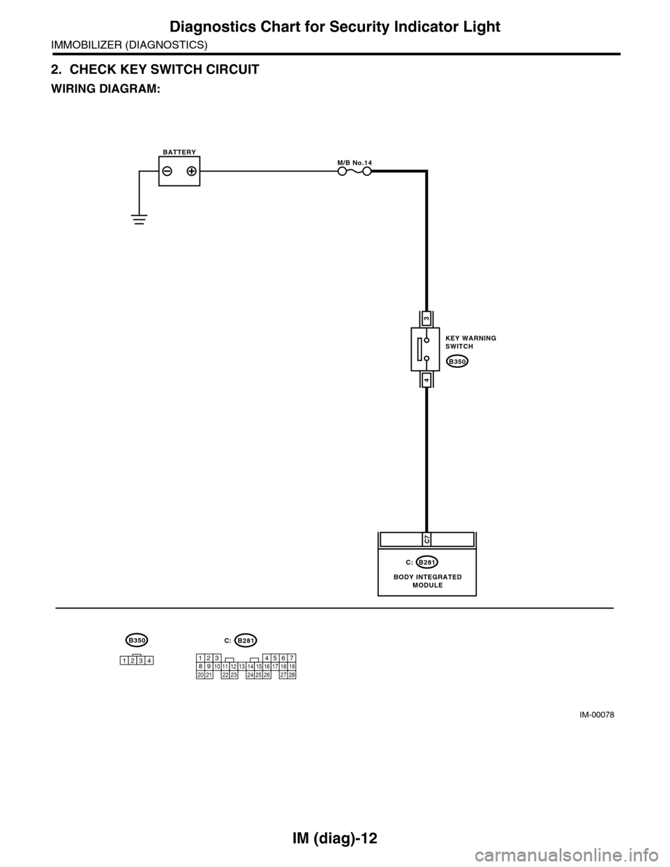
2. CHECK KEY SWITCH CIRCUIT
WIRING DIAGRAM:
IM-00078
B350
KEY WARNINGSWITCH
B281
BODY INTEGRATEDMODULE
BATTERYM/B No.14
C7
3
4
C:
567821943102422 23 25111213141526 27281617181920 21
B281C:B350
1234
Page 433 of 2453

IM (diag)-17
Diagnostic Procedure with Diagnostic Trouble Code (DTC)
IMMOBILIZER (DIAGNOSTICS)
B: DTC P1570 ANTENNA
DTC DETECTING CONDITION:
Faulty antenna
WIRING DIAGRAM:
IM-00110
C20C21
B351
12
12
B281C:
B351
567821943102422 23 25111213141526 27281617181920 21
B281C:
BODY INTEGRATED UNIT
ANTENNA
Page 436 of 2453
IM (diag)-20
Diagnostic Procedure with Diagnostic Trouble Code (DTC)
IMMOBILIZER (DIAGNOSTICS)
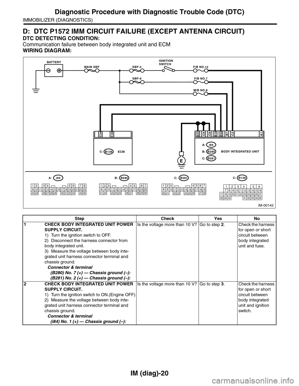
D: DTC P1572 IMM CIRCUIT FAILURE (EXCEPT ANTENNA CIRCUIT)
DTC DETECTING CONDITION:
Communication failure between body integrated unit and ECM
WIRING DIAGRAM:
MAIN SBF
SBF-8
SBF-3BATTERYF/B NO.12
IGNITIONSWITCH
A1B28B18C9C2B7C8
E
F/B NO.7
M/B NO.8
BODY INTEGRATED UNIT
i84A:
B280B:
B281C:
B22
567821943102422 23 25111213141526 27281617181920 21
B281i84
1234567891011121314151617181920212223242526272829303132333435
5467821931022 231112131415242526 2716171828 29192021 30
B280A:C:B:B136C:
C26C34
B136C:ECM
IM-00142
16101112131415252430
9871718192028212223293231
123456
2726333435
Step Check Yes No
1CHECK BODY INTEGRATED UNIT POWER
SUPPLY CIRCUIT.
1) Turn the ignition switch to OFF.
2) Disconnect the harness connector from
body integrated unit.
3) Measure the voltage between body inte-
grated unit harness connector terminal and
chassis ground.
Connector & terminal
(B280) No. 7 (+) — Chassis ground (–):
(B281) No. 2 (+) — Chassis ground (–):
Is the voltage more than 10 V? Go to step 2.Check the harness
for open or shor t
circuit between
body integrated
unit and fuse.
2CHECK BODY INTEGRATED UNIT POWER
SUPPLY CIRCUIT.
1) Turn the ignition switch to ON.(Engine OFF)
2) Measure the voltage between body inte-
grated unit harness connector terminal and
chassis ground.
Connector & terminal
(i84) No. 1 (+) — Chassis ground (–):
Is the voltage more than 10 V? Go to step 3.Check the harness
for open or shor t
circuit between
body integrated
unit and ignition
switch.
Page 443 of 2453
IDI-4
Combination Meter System
INSTRUMENTATION/DRIVER INFO
2. Combination Meter System
A: WIRING DIAGRAM
1. COMBINATION METER
B: INSPECTION
1. SELF-DIAGNOSIS
The self-diagnosis (checking of each meter, warn-
ing light, indicator, illumination, LCD, buzzer
sound) of combination meter can be performed in
the following procedure.
1) Turn the ignition switch to ON while turning the
small light to OFF.
2) Step 1) Turn the small light switch to ON within 3
seconds after step 1), then press the odo/tripmeter
knob three times.
3) Turn the small light switch to OFF, and press the
odo/trip knob three times.
4) Turn the small light switch to ON, and press the
odo/trip knob three times.
NOTE:
•Perform the steps described in 2) and 4) within
10 seconds after the ignition switch is turned to ON.
•When pressing the odo/trip meter knob four
times, the display changes to DTC display mode
(ECM, TCM).
tem.>When the self-diagnosis function operates,
the warning light, indicator, and LCD display are
checked, then every press of the odo/trip meter
knob will initiate the operation checks in the order
of meter, illumination and buzzer.
INSPECTION, Combination Meter System.> Turn
the ignition switch to OFF to cancel the self-diagno-
sis function.
•When the engine starts during diagnosis, the
self-diagnosis function is not cancelled, however,
once the vehicle starts driving, the self-diagnosis
function is cancelled automatically for safety.