compression ratio SUBARU TRIBECA 2009 1.G Service Workshop Manual
[x] Cancel search | Manufacturer: SUBARU, Model Year: 2009, Model line: TRIBECA, Model: SUBARU TRIBECA 2009 1.GPages: 2453, PDF Size: 46.32 MB
Page 1089 of 2453
VDC-8
VDC Control Module & Hydraulic Control Unit (VDCCM&H/U)
VEHICLE DYNAMICS CONTROL (VDC)
4) Connect the VDCCM&H/U connectors.
NOTE:
•Be sure to remove all foreign matter from inside
the connector before connecting.
•Make sure the VDCCM&H/U connector is se-
curely locked.
5) Bleed air from the brake system.
C: INSPECTION
1) Check the condition of connection and settle-
ment of connector.
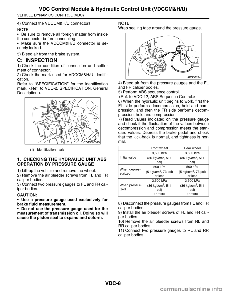
2) Check the mark used for VDCCM&H/U identifi-
cation.
Refer to “SPECIFICATION” for the identification
mark.
1. CHECKING THE HYDRAULIC UNIT ABS
OPERATION BY PRESSURE GAUGE
1) Lift-up the vehicle and remove the wheel.
2) Remove the air bleeder screws from FL and FR
caliper bodies.
3) Connect two pressure gauges to FL and FR cal-
iper bodies.
CAUTION:
•Use a pressure gauge used exclusively for
brake fluid measurement.
•Do not use the pressure gauge used for the
measurement of transmission oil. Doing so will
cause the piston seal to expand and deform.
NOTE:
Wrap sealing tape around the pressure gauge.
4) Bleed air from the pressure gauges and the FL
and FR caliper bodies.
5) Perform ABS sequence control.
6) When the hydraulic unit begins to work, first the
FL side performs decompression, hold and com-
pression, and then the FR side performs decom-
pression, hold and compression.
7) Read values indicated on the pressure gauge
and check if the fluctuation of the values between
decompression and compression meets the stan-
dard values. Depress the brake pedal and check
that the kick-back is normal, and tightness is nor-
mal.
8) Disconnect the pressure gauges from FL and FR
caliper bodies.
9) Install the air bleeder screws of FL and FR cali-
per bodies.
10) Remove the air bleeder screws from RL and
RR caliper bodies.
11) Connect two pressure gauges to RL and RR
caliper bodies.
(1) Identification mark
VDC00345
(1)
Front wheelRear wheel
Initial value
3,500 kPa
(36 kgf/cm2, 511
psi)
3,500 kPa
(36 kgf/cm2, 511
psi)
When depres-
surized
500 kPa
(5 kgf/cm2, 73 psi)
or less
500 kPa
(5 kgf/cm2, 73 psi)
or less
When pressur-
ized
3,500 kPa
(36 kgf/cm2, 511
psi)
or more
3,500 kPa
(36 kgf/cm2, 511
psi)
or more
ABS00134
Page 1090 of 2453
VDC-9
VDC Control Module & Hydraulic Control Unit (VDCCM&H/U)
VEHICLE DYNAMICS CONTROL (VDC)
12) Bleed air from the brake system.
13) Bleed air from RL and RR caliper bodies, and
pressure gauge.
14) Perform ABS sequence control.
15) When the hydraulic unit begins to work, first the
RR side performs decompression, hold and com-
pression, and then the RL side performs decom-
pression, hold and compression.
16) Read values indicated on the pressure gauge
and check if the fluctuation of the values between
decompression and compression meets specifica-
tion. Depress the brake pedal and check that the
kick-back is normal, and tightness is normal.
17) Disconnect the pressure gauge from the RL
and RR caliper bodies.
18) Install the air bleeder screws of RL and RR cal-
iper bodies.
19) Bleed air from the brake system.
2. CHECKING THE HYDRAULIC UNIT ABS
OPERATION WITH THE BRAKE TESTER
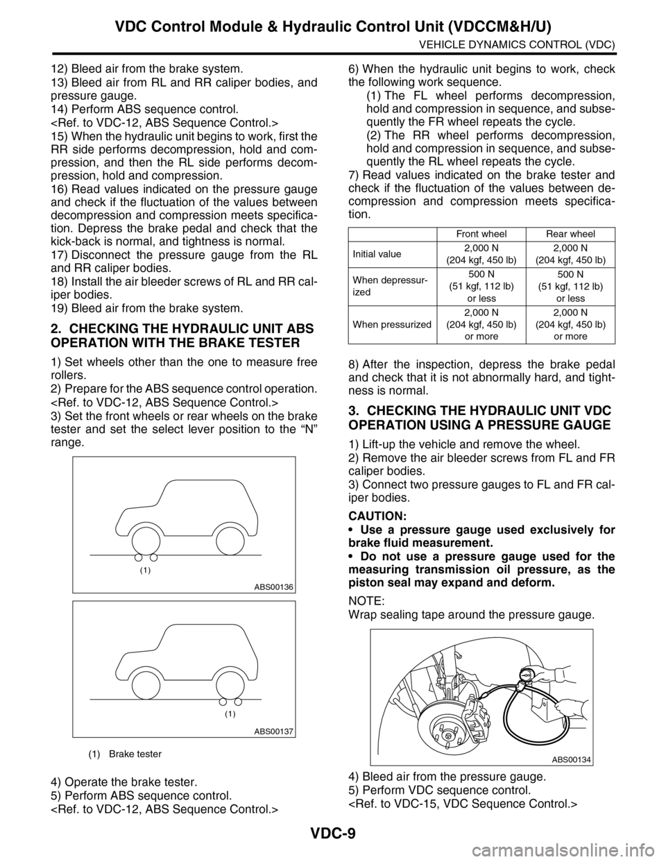
1) Set wheels other than the one to measure free
rollers.
2) Prepare for the ABS sequence control operation.
3) Set the front wheels or rear wheels on the brake
tester and set the select lever position to the “N”
range.
4) Operate the brake tester.
5) Perform ABS sequence control.
6) When the hydraulic unit begins to work, check
the following work sequence.
(1) The FL wheel performs decompression,
hold and compression in sequence, and subse-
quently the FR wheel repeats the cycle.
(2) The RR wheel performs decompression,
hold and compression in sequence, and subse-
quently the RL wheel repeats the cycle.
7) Read values indicated on the brake tester and
check if the fluctuation of the values between de-
compression and compression meets specifica-
tion.
8) After the inspection, depress the brake pedal
and check that it is not abnormally hard, and tight-
ness is normal.
3. CHECKING THE HYDRAULIC UNIT VDC
OPERATION USING A PRESSURE GAUGE
1) Lift-up the vehicle and remove the wheel.
2) Remove the air bleeder screws from FL and FR
caliper bodies.
3) Connect two pressure gauges to FL and FR cal-
iper bodies.
CAUTION:
•Use a pressure gauge used exclusively for
brake fluid measurement.
•Do not use a pressure gauge used for the
measuring transmission oil pressure, as the
piston seal may expand and deform.
NOTE:
Wrap sealing tape around the pressure gauge.
4) Bleed air from the pressure gauge.
5) Perform VDC sequence control.
(1) Brake tester
ABS00136
(1)
ABS00137
(1)
Front wheelRear wheel
Initial value2,000 N
(204 kgf, 450 lb)
2,000 N
(204 kgf, 450 lb)
When depressur-
ized
500 N
(51 kgf, 112 lb)
or less
500 N
(51 kgf, 112 lb)
or less
When pressurized
2,000 N
(204 kgf, 450 lb)
or more
2,000 N
(204 kgf, 450 lb)
or more
ABS00134
Page 1095 of 2453
VDC-14
ABS Sequence Control
VEHICLE DYNAMICS CONTROL (VDC)
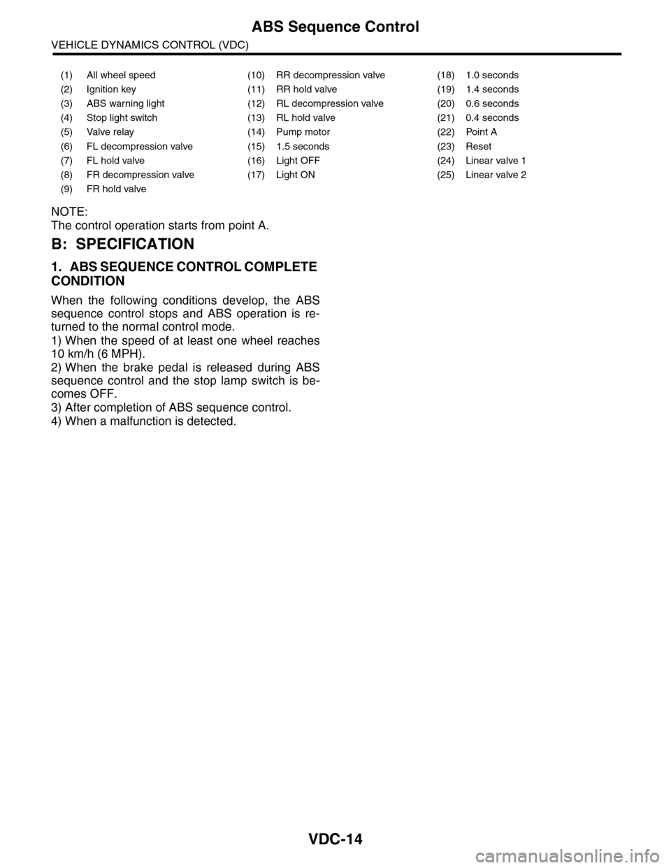
NOTE:
The control operation starts from point A.
B: SPECIFICATION
1. ABS SEQUENCE CONTROL COMPLETE
CONDITION
When the following conditions develop, the ABS
sequence control stops and ABS operation is re-
turned to the normal control mode.
1) When the speed of at least one wheel reaches
10 km/h (6 MPH).
2) When the brake pedal is released during ABS
sequence control and the stop lamp switch is be-
comes OFF.
3) After completion of ABS sequence control.
4) When a malfunction is detected.
(1) All wheel speed (10) RR decompression valve (18) 1.0 seconds
(2) Ignition key (11) RR hold valve (19) 1.4 seconds
(3) ABS warning light (12) RL decompression valve (20) 0.6 seconds
(4) Stop light switch (13) RL hold valve (21) 0.4 seconds
(5) Valve relay (14) Pump motor (22) Point A
(6) FL decompression valve (15) 1.5 seconds (23) Reset
(7) FL hold valve (16) Light OFF (24) Linear valve 1
(8) FR decompression valve (17) Light ON (25) Linear valve 2
(9) FR hold valve
Page 1098 of 2453
VDC-17
VDC Sequence Control
VEHICLE DYNAMICS CONTROL (VDC)
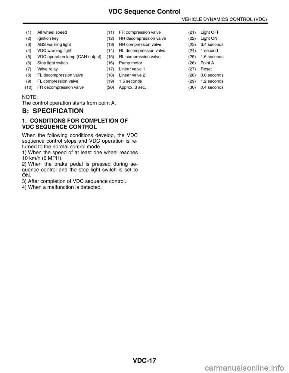
NOTE:
The control operation starts from point A.
B: SPECIFICATION
1. CONDITIONS FOR COMPLETION OF
VDC SEQUENCE CONTROL
When the following conditions develop, the VDC
sequence control stops and VDC operation is re-
turned to the normal control mode.
1) When the speed of at least one wheel reaches
10 km/h (6 MPH).
2) When the brake pedal is pressed during se-
quence control and the stop light switch is set to
ON.
3) After completion of VDC sequence control.
4) When a malfunction is detected.
(1) All wheel speed (11) FR compression valve (21) Light OFF
(2) Ignition key (12) RR decompression valve (22) Light ON
(3) ABS warning light (13) RR compression valve (23) 3.4 seconds
(4) VDC warning light (14) RL decompression valve (24) 1 second
(5) VDC operation lamp (CAN output) (15) RL compression valve (25) 1.6 seconds
(6) Stop light switch (16) Pump motor (26) Point A
(7) Valve relay (17) Linear valve 1 (27) Reset
(8) FL decompression valve (18) Linear valve 2 (28) 0.8 seconds
(9) FL compression valve (19) 1.5 seconds (29) 1.2 seconds
(10) FR decompression valve (20) Approx. 3 sec. (30) 0.4 seconds
Page 1409 of 2453
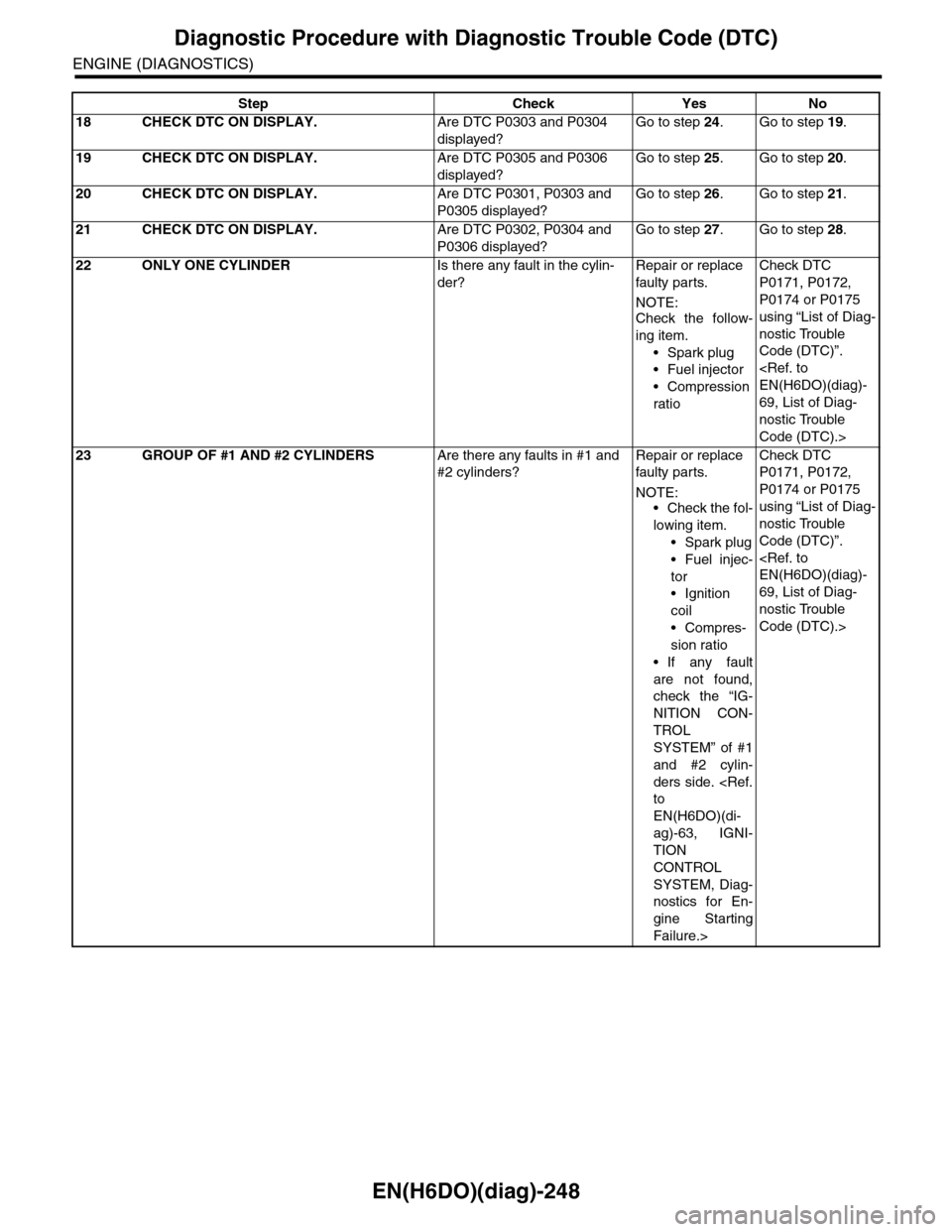
EN(H6DO)(diag)-248
Diagnostic Procedure with Diagnostic Trouble Code (DTC)
ENGINE (DIAGNOSTICS)
18 CHECK DTC ON DISPLAY.Are DTC P0303 and P0304
displayed?
Go to step 24.Go to step 19.
19 CHECK DTC ON DISPLAY.Are DTC P0305 and P0306
displayed?
Go to step 25.Go to step 20.
20 CHECK DTC ON DISPLAY.Are DTC P0301, P0303 and
P0305 displayed?
Go to step 26.Go to step 21.
21 CHECK DTC ON DISPLAY.Are DTC P0302, P0304 and
P0306 displayed?
Go to step 27.Go to step 28.
22 ONLY ONE CYLINDERIs there any fault in the cylin-
der?
Repair or replace
faulty par ts.
NOTE:Check the follow-
ing item.
•Spark plug
•Fuel injector
•Compression
ratio
Check DTC
P0171, P0172,
P0174 or P0175
using “List of Diag-
nostic Trouble
Code (DTC)”.
69, List of Diag-
nostic Trouble
Code (DTC).>
23 GROUP OF #1 AND #2 CYLINDERSAre there any faults in #1 and
#2 cylinders?
Repair or replace
faulty par ts.
NOTE:•Check the fol-
lowing item.
•Spark plug
•Fuel injec-
tor
•Ignition
coil
•Compres-
sion ratio
•If any fault
are not found,
check the “IG-
NITION CON-
TROL
SYSTEM” of #1
and #2 cylin-
ders side.
EN(H6DO)(di-
ag)-63, IGNI-
TION
CONTROL
SYSTEM, Diag-
nostics for En-
gine Starting
Failure.>
Check DTC
P0171, P0172,
P0174 or P0175
using “List of Diag-
nostic Trouble
Code (DTC)”.
69, List of Diag-
nostic Trouble
Code (DTC).>
Step Check Yes No
Page 1411 of 2453
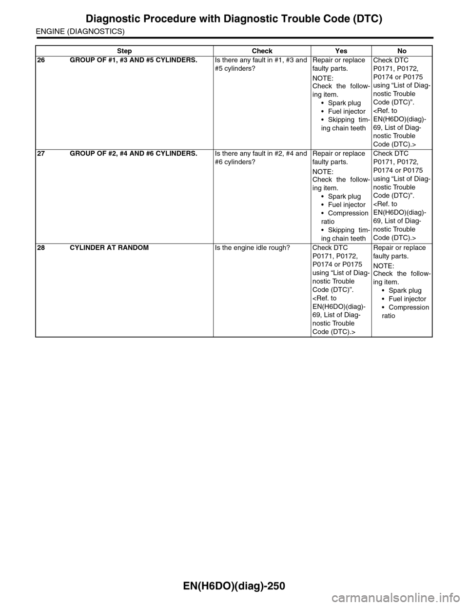
EN(H6DO)(diag)-250
Diagnostic Procedure with Diagnostic Trouble Code (DTC)
ENGINE (DIAGNOSTICS)
26 GROUP OF #1, #3 AND #5 CYLINDERS.Is there any fault in #1, #3 and
#5 cylinders?
Repair or replace
faulty par ts.
NOTE:
Check the follow-
ing item.
•Spark plug
•Fuel injector
•Skipping tim-
ing chain teeth
Check DTC
P0171, P0172,
P0174 or P0175
using “List of Diag-
nostic Trouble
Code (DTC)”.
69, List of Diag-
nostic Trouble
Code (DTC).>
27 GROUP OF #2, #4 AND #6 CYLINDERS.Is there any fault in #2, #4 and
#6 cylinders?
Repair or replace
faulty par ts.
NOTE:Check the follow-
ing item.
•Spark plug
•Fuel injector
•Compression
ratio
•Skipping tim-
ing chain teeth
Check DTC
P0171, P0172,
P0174 or P0175
using “List of Diag-
nostic Trouble
Code (DTC)”.
69, List of Diag-
nostic Trouble
Code (DTC).>
28 CYLINDER AT RANDOMIs the engine idle rough? Check DTC
P0171, P0172,
P0174 or P0175
using “List of Diag-
nostic Trouble
Code (DTC)”.
69, List of Diag-
nostic Trouble
Code (DTC).>
Repair or replace
faulty par ts.
NOTE:Check the follow-
ing item.
•Spark plug
•Fuel injector
•Compression
ratio
Step Check Yes No
Page 1868 of 2453
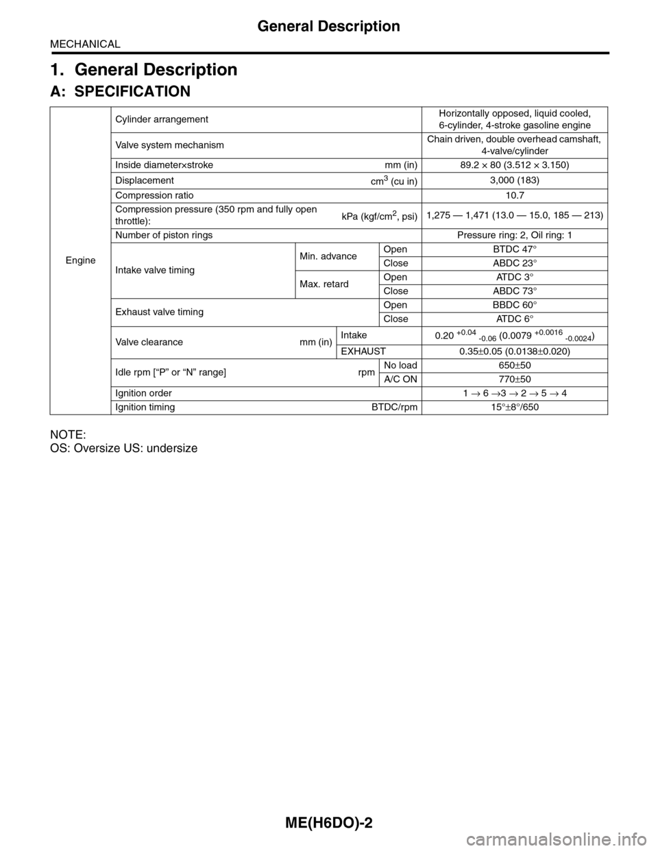
ME(H6DO)-2
General Description
MECHANICAL
1. General Description
A: SPECIFICATION
NOTE:
OS: Oversize US: undersize
Engine
Cylinder arrangementHorizontally opposed, liquid cooled,
6-cylinder, 4-stroke gasoline engine
Va l ve s y s t e m m e c h a n i s mChain driven, double overhead camshaft,
4-valve/cylinder
Inside diameter×stroke mm (in) 89.2 × 80 (3.512 × 3.150)
Displacementcm3 (cu in)3,000 (183)
Compression ratio10.7
Compression pressure (350 rpm and fully open
throttle):kPa (kgf/cm2, psi)1,275 — 1,471 (13.0 — 15.0, 185 — 213)
Number of piston rings Pressure ring: 2, Oil ring: 1
Intake valve timing
Min. advanceOpen BTDC 47°
Close ABDC 23°
Max. retardOpen ATDC 3°
Close ABDC 73°
Exhaust valve timingOpen BBDC 60°
Close ATDC 6°
Va l ve c l e a r a n c e m m ( i n )Intake0.20 +0.04 -0.06 (0.0079 +0.0016 -0.0024)
EXHAUST 0.35±0.05 (0.0138±0.020)
Idle rpm [“P” or “N” range] rpmNo load 650±50
A/C ON 770±50
Ignition order 1 → 6 →3 → 2 → 5 → 4
Ignition timing BTDC/rpm 15°±8°/650
Page 1886 of 2453
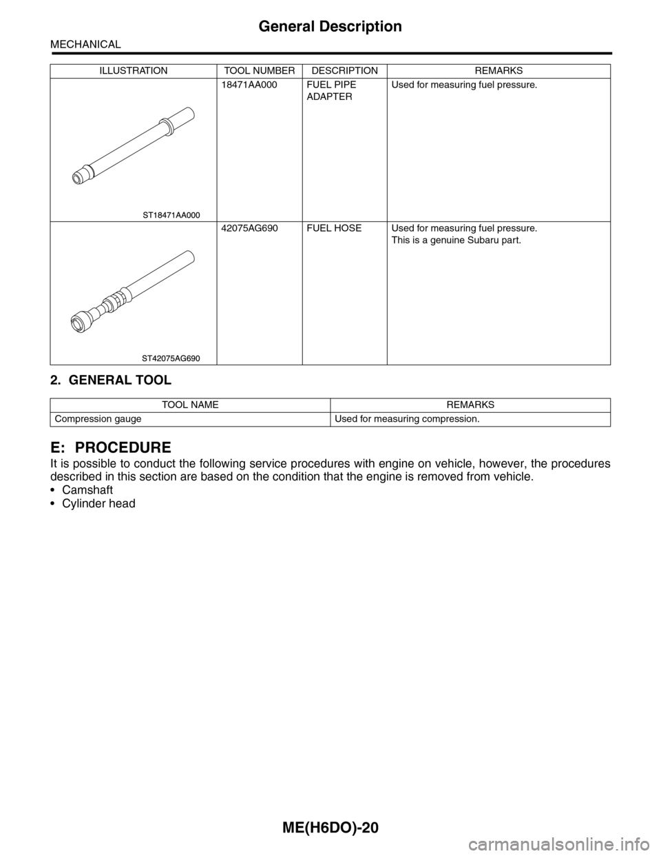
ME(H6DO)-20
General Description
MECHANICAL
2. GENERAL TOOL
E: PROCEDURE
It is possible to conduct the following service procedures with engine on vehicle, however, the procedures
described in this section are based on the condition that the engine is removed from vehicle.
•Camshaft
•Cylinder head
18471AA000 FUEL PIPE
ADAPTER
Used for measuring fuel pressure.
42075AG690 FUEL HOSE Used for measuring fuel pressure.
This is a genuine Subaru part.
TOOL NAME REMARKS
Compression gauge Used for measuring compression.
ILLUSTRATION TOOL NUMBER DESCRIPTION REMARKS
Page 1887 of 2453
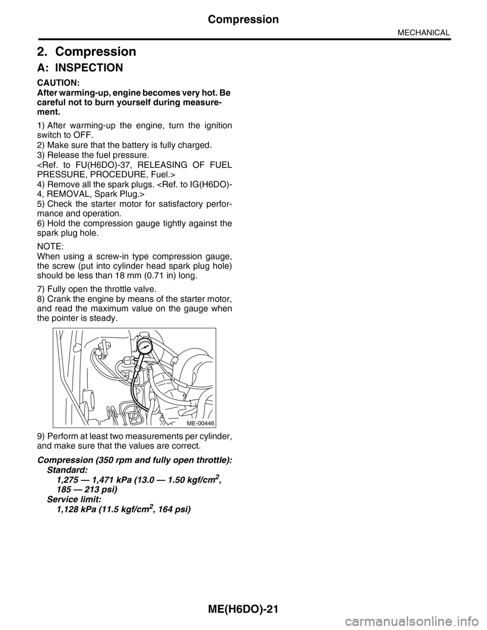
ME(H6DO)-21
Compression
MECHANICAL
2. Compression
A: INSPECTION
CAUTION:
After warming-up, engine becomes very hot. Be
careful not to burn yourself during measure-
ment.
1) After warming-up the engine, turn the ignition
switch to OFF.
2) Make sure that the battery is fully charged.
3) Release the fuel pressure.
4) Remove all the spark plugs.
5) Check the starter motor for satisfactory perfor-
mance and operation.
6) Hold the compression gauge tightly against the
spark plug hole.
NOTE:
When using a screw-in type compression gauge,
the screw (put into cylinder head spark plug hole)
should be less than 18 mm (0.71 in) long.
7) Fully open the throttle valve.
8) Crank the engine by means of the starter motor,
and read the maximum value on the gauge when
the pointer is steady.
9) Perform at least two measurements per cylinder,
and make sure that the values are correct.
Compression (350 rpm and fully open throttle):
Standard:
1,275 — 1,471 kPa (13.0 — 1.50 kgf/cm2,
185 — 213 psi)
Service limit:
1,128 kPa (11.5 kgf/cm2, 164 psi)
ME-00446
Page 1952 of 2453
ME(H6DO)-86
Engine Trouble in General
MECHANICAL
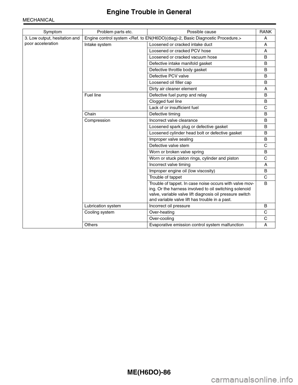
3. Low output, hesitation and
poor acceleration
Engine control system
Intake system Loosened or cracked intake duct A
Loosened or cracked PCV hose A
Loosened or cracked vacuum hose B
Defective intake manifold gasket B
Defective throttle body gasket B
Defective PCV valve B
Loosened oil filler cap B
Dirty air cleaner element A
Fuel line Defective fuel pump and relay B
Clogged fuel line B
Lack of or insufficient fuel C
Chain Defective timing B
Compression Incorrect valve clearance B
Loosened spark plug or defective gasket B
Loosened cylinder head bolt or defective gasket B
Improper valve sealing B
Defective valve stem C
Wor n or broken valve spr ing B
Wor n or stuck piston r ings, cylinder and piston C
Incorrect valve timing A
Improper engine oil (low viscosity) B
Tr o u b l e o f t a p p e t C
Tr o u b l e o f t a p p e t . I n c a s e n o i s e o c c u r s w i t h v a l v e m o v -
ing. Or the harness involved to oil switching solenoid
valve, variable valve lift diagnosis oil pressure switch
and variable valve lift has trouble in a past.
B
Lubrication system Incorrect oil pressure B
Cooling system Over-heating C
Over-cooling C
Others Evaporative emission control system malfunction A
Symptom Problem parts etc. Possible cause RANK