low oil pressure SUBARU TRIBECA 2009 1.G Service Repair Manual
[x] Cancel search | Manufacturer: SUBARU, Model Year: 2009, Model line: TRIBECA, Model: SUBARU TRIBECA 2009 1.GPages: 2453, PDF Size: 46.32 MB
Page 2251 of 2453
5AT(diag)-134
General Diagnostic Table
AUTOMATIC TRANSMISSION (DIAGNOSTICS)
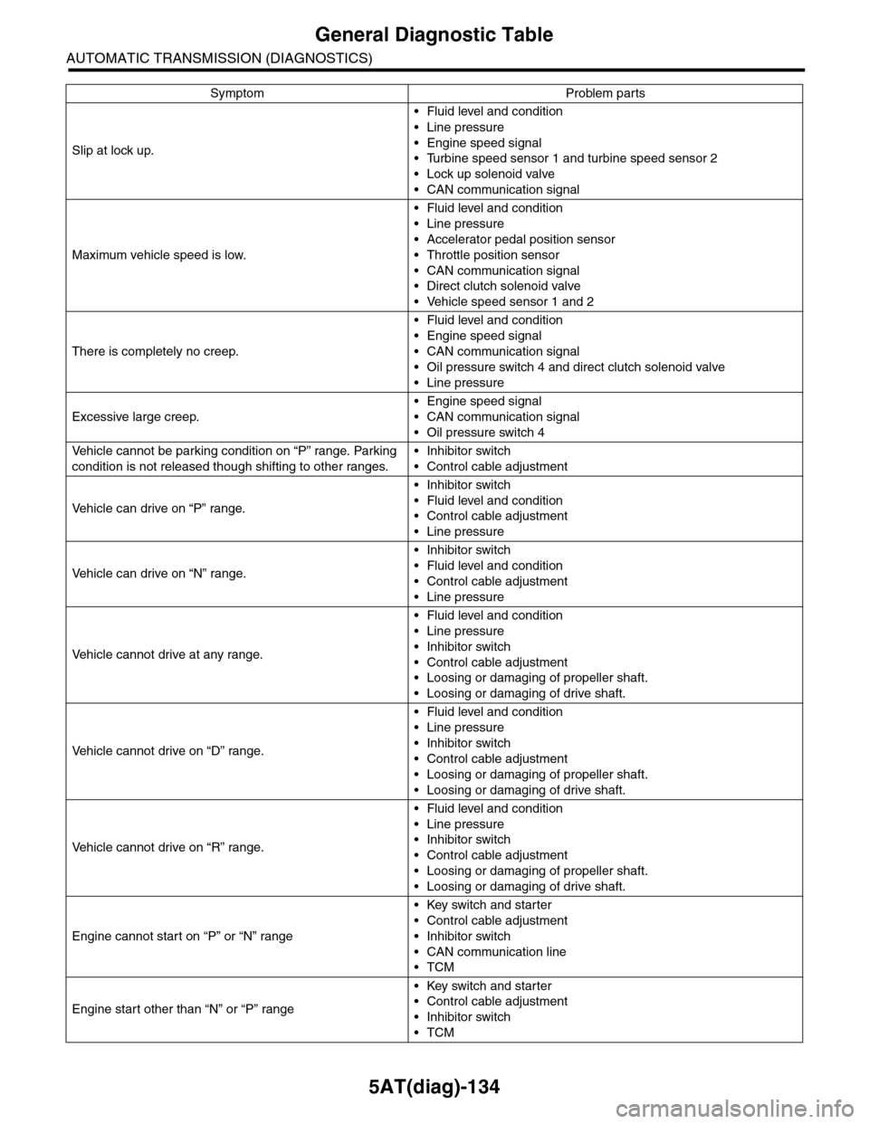
Slip at lock up.
•Fluid level and condition
•Line pressure
•Engine speed signal
•Turbine speed sensor 1 and turbine speed sensor 2
•Lock up solenoid valve
•CAN communication signal
Maximum vehicle speed is low.
•Fluid level and condition
•Line pressure
•Accelerator pedal position sensor
•Throttle position sensor
•CAN communication signal
•Direct clutch solenoid valve
•Vehicle speed sensor 1 and 2
There is completely no creep.
•Fluid level and condition
•Engine speed signal
•CAN communication signal
•Oil pressure switch 4 and direct clutch solenoid valve
•Line pressure
Excessive large creep.
•Engine speed signal
•CAN communication signal
•Oil pressure switch 4
Ve h i c l e c a n n o t b e p a r k i n g c o n d i t i o n o n “ P ” r a n g e . Pa r k i n g
condition is not released though shifting to other ranges.
•Inhibitor switch
•Control cable adjustment
Ve h i c l e c a n d r i v e o n “ P ” r a n g e .
•Inhibitor switch
•Fluid level and condition
•Control cable adjustment
•Line pressure
Ve h i c l e c a n d r i v e o n “ N ” r a n g e .
•Inhibitor switch
•Fluid level and condition
•Control cable adjustment
•Line pressure
Ve h i c l e c a n n o t d r i v e a t a n y r a n g e .
•Fluid level and condition
•Line pressure
•Inhibitor switch
•Control cable adjustment
•Loosing or damaging of propeller shaft.
•Loosing or damaging of drive shaft.
Ve h i c l e c a n n o t d r i v e o n “ D ” r a n g e .
•Fluid level and condition
•Line pressure
•Inhibitor switch
•Control cable adjustment
•Loosing or damaging of propeller shaft.
•Loosing or damaging of drive shaft.
Ve h i c l e c a n n o t d r i v e o n “ R ” r a n g e .
•Fluid level and condition
•Line pressure
•Inhibitor switch
•Control cable adjustment
•Loosing or damaging of propeller shaft.
•Loosing or damaging of drive shaft.
Engine cannot start on “P” or “N” range
•Key switch and starter
•Control cable adjustment
•Inhibitor switch
•CAN communication line
•TCM
Engine start other than “N” or “P” range
•Key switch and starter
•Control cable adjustment
•Inhibitor switch
•TCM
Symptom Problem parts
Page 2316 of 2453
WI-32
Engine Electrical System
WIRING SYSTEM
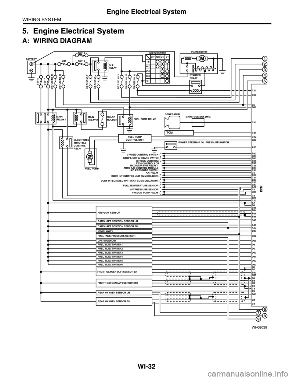
5. Engine Electrical System
A: WIRING DIAGRAM
WI-08039
678
1
2
3
4
5
C20
C32
C31
B5B19
B33
A33
C10
ECMC1B25C8A27
C21C23A7
D29
B2
BATTERY
M/B FUSE NO. 11SBF-7
SBF
SBF-5
SBF-8
SBF-6
STARTERRELAY
IG 2RELAY
IGNITION SWITCHOFF+B
ACC
IG2
IG1
ACCONST
ST
STARTER MOTOR
MAINRELAY 1
ELECTRONICTHROTTLECONTROLRELAY
FUEL PUMP RELAY
FUEL PUMP
FUEL PUMPCONTROL UNIT
MAINRELAY 2RELAYHOLDER
A21
A11A22
B34
B35
B7B6
B11B10
B9B8
C2
B26AIR FLOW SENSOR
CAMSHAFT POSITION SENSOR LH
CPC SOLENOID
B1
C3C5B15
B4C4
POWER STEERING OIL PRESSURE SWITCH
C12
MAIN FUSE BOX (M/B)GENERATOR
B18
TCM
D8FUEL INJECTOR NO.1D9D10D11
PWM CONTROLLORAUTO A/C CONTROL MODULE
A/C RELAY
BODY INTEGRATED UNIT (CAN COMMUNICATION)
FUEL TEMPERATURE SENSOR
VACUUM PUMP RELAY
BODY INTEGRATED UNIT (IMMOBILIZER)
C18C29C24C33
C27
B24B12
B20B28
C26C34
C35B17
CRUISE CONTROL SWITCH
FUEL INJECTOR NO.2FUEL INJECTOR NO.3
C17DRAIN VALVE
FUEL INJECTOR NO.4D12D13FUEL INJECTOR NO.5FUEL INJECTOR NO.6
FRONT OXYGEN (A/F) SENSOR RH
REAR OXYGEN SENSOR RH
REAR OXYGEN SENSOR LH
FRONT OXYGEN (A/F) SENSOR LH
A/C PRESSURE SWITCH
M/V PRESSURE SENSOR
RADIATOR FAN RELAY 1
STOP LIGHT & BRAKE SWITCH(CRUISE CONTROL)
C9
FUEL TANK PRESSURE SENSORB32
M/B FUSE NO. 13F/B FUSE NO. 7F/B FUSE NO. 4F/B FUSE NO. 5F/B FUSE NO. 12F/B FUSE NO. 21
CAMSHAFT POSITION SENSOR RH
9
Page 2317 of 2453
WI-33
Engine Electrical System
WIRING SYSTEM
WI-08040
A3D2
D22D23
POWERCIRCUIT
COMBINATION METER
C16B27D18D19D20D21
C11C22
C6
B23B29B31B21
1
2
3
4
5
6
ACCELERATORPEDAL POSITIONSENSOR
JOINT CONNECTOR A
JOINT CONNECTOR
MALFUNCTION INDICATOR LIGHTOIL PRESSUREWARNING LIGHT
I/F
I/F
I/F
VDC CONTROL MODULE
IGNITION COIL NO.1
BODY INTEGRATED UNIT(CAN COMMUNICATION LINE)
OILPRESSURESWITCH
CRANKSHAFT POSITION SENSORA13A14
ENGINE GROUND
ECM
A18A28
D4D5
A19B22A6A29A34
D15B30
D14D17D16D31D30
ELECTRONIC THROTTLE CONTROL
A24
A25A16
A15
A32
D1
MANIFOLD ABSOLUTE PRESSURE SENSOR
ENGINE COOLANT TEMPRERATURE SENSOR
VVL DIAGNOSIS OIL PRESSURE SWITCH RH
D25D24
KNOCK SENSOR 2
D6D26D7
A5
MICRO COMPUTER
CAN TRANSCEIVER &RECEIVER
OIL SWITCHING SOLENOID VALVE RH
TA C H O -METER
SPEEDMETER
ENGINECOOLANTTEM-PERATUREGAUGE
DATA LINK CONNECTOR
TEST MODECONNECTOR
OIL TEMPERATURE SENSORA23
A31D3
VVL DIAGNOSIS OIL PRESSURE SWITCH LH
KNOCK SENSOR 1
OIL SWITCHING SOLENOID VALVE LH
INTAKE OIL FLOW CONTROL SOLENOID VALVE RH
INTAKE OIL FLOW CONTROL SOLENOID VALVE LH
IGNITION COIL NO.2 IGNITION COIL NO.3 IGNITION COIL NO.4 IGNITION COIL NO.5 IGNITION COIL NO.6
789
Page 2441 of 2453
WI-157
Engine Wiring Harness and Transmission Cord
WIRING SYSTEM
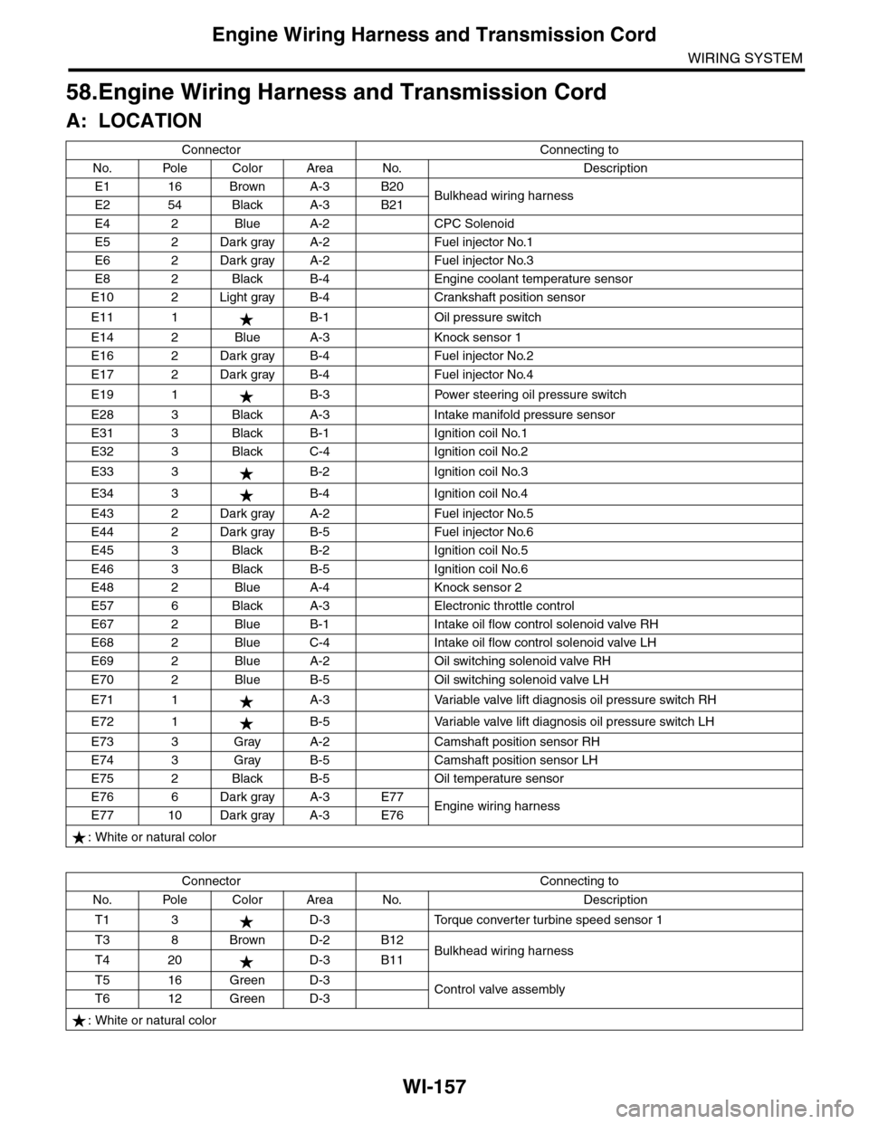
58.Engine Wiring Harness and Transmission Cord
A: LOCATION
Connector Connecting to
No. Pole Color Area No. Description
E1 16 Brown A-3 B20Bulkhead wiring harnessE2 54 Black A-3 B21
E4 2 Blue A-2 CPC Solenoid
E5 2 Dark gray A-2 Fuel injector No.1
E6 2 Dark gray A-2 Fuel injector No.3
E8 2 Black B-4 Engine coolant temperature sensor
E10 2 Light gray B-4 Crankshaft position sensor
E11 1 B-1 Oil pressure switch
E14 2 Blue A-3 Knock sensor 1
E16 2 Dark gray B-4 Fuel injector No.2
E17 2 Dark gray B-4 Fuel injector No.4
E19 1 B-3 Power steering oil pressure switch
E28 3 Black A-3 Intake manifold pressure sensor
E31 3 Black B-1 Ignition coil No.1
E32 3 Black C-4 Ignition coil No.2
E33 3 B-2 Ignition coil No.3
E34 3 B-4 Ignition coil No.4
E43 2 Dark gray A-2 Fuel injector No.5
E44 2 Dark gray B-5 Fuel injector No.6
E45 3 Black B-2 Ignition coil No.5
E46 3 Black B-5 Ignition coil No.6
E48 2 Blue A-4 Knock sensor 2
E57 6 Black A-3 Electronic throttle control
E67 2 Blue B-1 Intake oil flow control solenoid valve RH
E68 2 Blue C-4 Intake oil flow control solenoid valve LH
E69 2 Blue A-2 Oil switching solenoid valve RH
E70 2 Blue B-5 Oil switching solenoid valve LH
E71 1 A-3 Variable valve lift diagnosis oil pressure switch RH
E72 1 B-5 Variable valve lift diagnosis oil pressure switch LH
E73 3 Gray A-2 Camshaft position sensor RH
E74 3 Gray B-5 Camshaft position sensor LH
E75 2 Black B-5 Oil temperature sensor
E76 6 Dark gray A-3 E77Engine wiring harnessE77 10 Dark gray A-3 E76
: White or natural color
Connector Connecting to
No. Pole Color Area No. Description
T1 3 D-3 Torque converter turbine speed sensor 1
T3 8 Brown D-2 B12Bulkhead wiring harnessT4 20 D-3 B11
T5 16 Green D-3Control valve assemblyT6 12 Green D-3
: White or natural color