ignition SUBARU TRIBECA 2009 1.G Service Workshop Manual
[x] Cancel search | Manufacturer: SUBARU, Model Year: 2009, Model line: TRIBECA, Model: SUBARU TRIBECA 2009 1.GPages: 2453, PDF Size: 46.32 MB
Page 14 of 2453
AB-15
Driver’s Airbag Module
AIRBAG SYSTEM
4. Driver’s Airbag Module
A: REMOVAL
CAUTION:
Refer to “CAUTION” of “General Description”
before handling the airbag module.
1) Position the front wheels straight ahead. (After
moving a vehicle more than 5 m (16 ft) with front
wheels positioned straight ahead, make sure that
the vehicle moves straight ahead).
2) Turn the ignition switch to OFF.
3) Disconnect the ground cable from battery and
wait for at least 20 seconds before starting work.
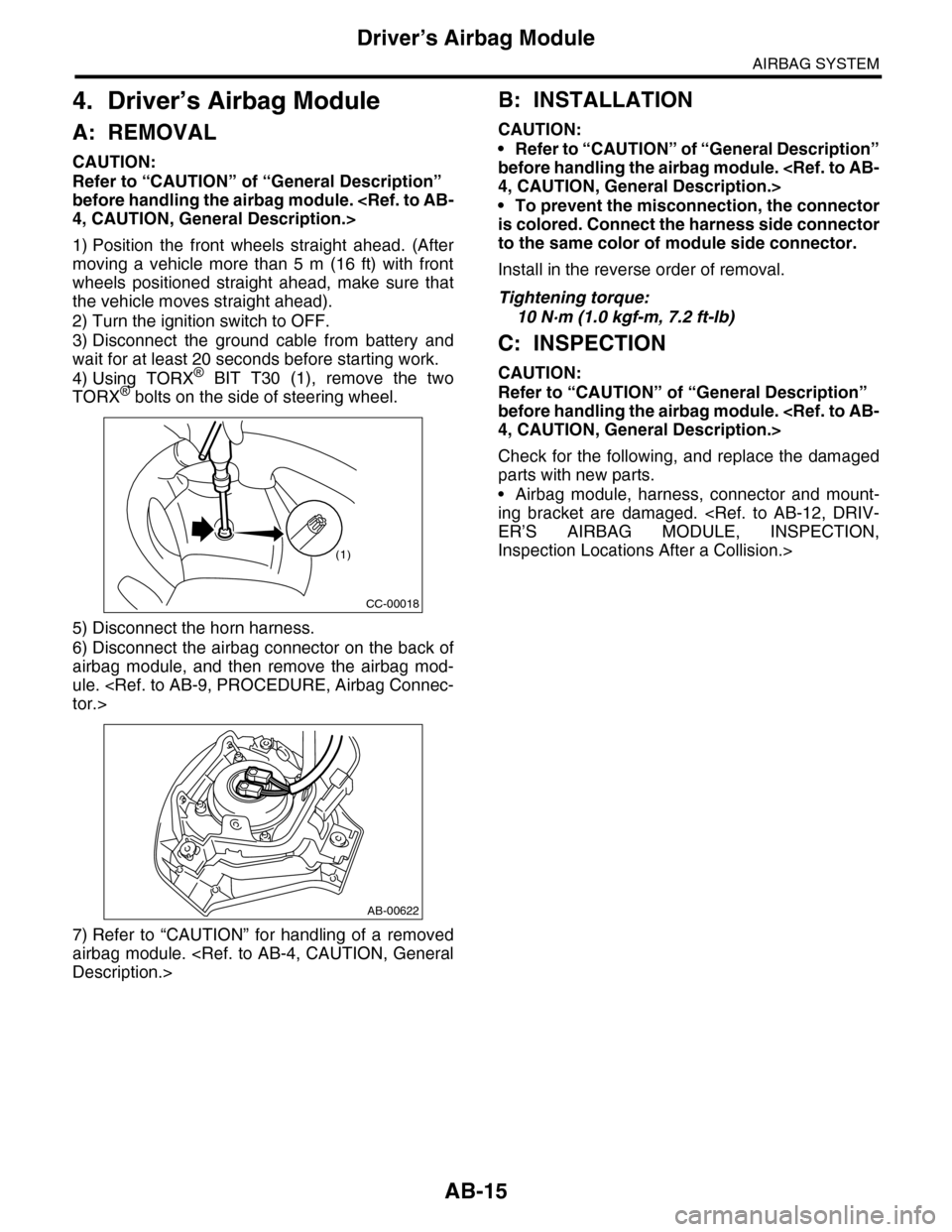
4) Using TORX® BIT T30 (1), remove the two
TORX® bolts on the side of steering wheel.
5) Disconnect the horn harness.
6) Disconnect the airbag connector on the back of
airbag module, and then remove the airbag mod-
ule.
7) Refer to “CAUTION” for handling of a removed
airbag module.
B: INSTALLATION
CAUTION:
•Refer to “CAUTION” of “General Description”
before handling the airbag module.
•To prevent the misconnection, the connector
is colored. Connect the harness side connector
to the same color of module side connector.
Install in the reverse order of removal.
Tightening torque:
10 N·m (1.0 kgf-m, 7.2 ft-lb)
C: INSPECTION
CAUTION:
Refer to “CAUTION” of “General Description”
before handling the airbag module.
Check for the following, and replace the damaged
parts with new parts.
•Airbag module, harness, connector and mount-
ing bracket are damaged.
Inspection Locations After a Collision.>
CC-00018
(1)
AB-00622
Page 15 of 2453
AB-16
Passenger’s Airbag Module
AIRBAG SYSTEM
5. Passenger’s Airbag Module
A: REMOVAL
CAUTION:
Refer to “CAUTION” of “General Description”
before handling the airbag module.
1) Turn the ignition switch to OFF.
2) Disconnect the ground cable from battery and
wait for at least 20 seconds before starting work.
3) Remove the glove box.
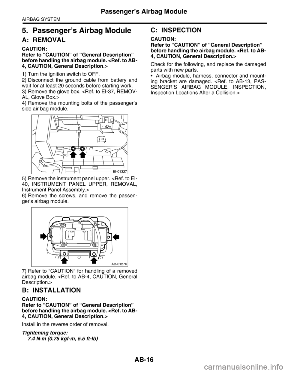
4) Remove the mounting bolts of the passenger’s
side air bag module.
5) Remove the instrument panel upper.
Instrument Panel Assembly.>
6) Remove the screws, and remove the passen-
ger’s airbag module.
7) Refer to “CAUTION” for handling of a removed
airbag module.
B: INSTALLATION
CAUTION:
Refer to “CAUTION” of “General Description”
before handling the airbag module.
Install in the reverse order of removal.
Tightening torque:
7.4 N·m (0.75 kgf-m, 5.5 ft-lb)
C: INSPECTION
CAUTION:
Refer to “CAUTION” of “General Description”
before handling the airbag module.
Check for the following, and replace the damaged
parts with new parts.
•Airbag module, harness, connector and mount-
ing bracket are damaged.
Inspection Locations After a Collision.>
EI-01327
AB-01276
Page 16 of 2453
AB-17
Side Airbag Module
AIRBAG SYSTEM
6. Side Airbag Module
A: REMOVAL
CAUTION:
Refer to “CAUTION” of “General Description”
before handling the airbag module.
NOTE:
Remove the passenger’s side by referring to driv-
er’s side.
1) Turn the ignition switch to OFF.
2) Disconnect the ground cable from battery and
wait for at least 20 seconds before starting work.
3) Remove the front seats.
4) Disconnect the connector from the back side of
seat cushion assembly, then remove the side air-
bag harness.
5) Remove the backrest cover.
6) Remove the nuts, and remove the side airbag
module assembly from the back rest frame assem-
bly.
B: INSTALLATION
CAUTION:
•Refer to “CAUTION” of “General Description”
before handling the airbag module.
•Be sure to perform the system calibration for
occupant detection system after passenger’s
seat installation.
Subaru Select Monitor.>
1) Make sure that there is no foreign matter on side
airbag module.
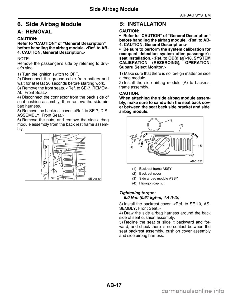
2) Install the side airbag module (A) to backrest
frame assembly.
CAUTION:
When attaching the side airbag module assem-
bly, make sure to sandwitch the seat back cov-
er between the seat back side bracket and side
airbag module.
Tightening torque:
6.0 N·m (0.61 kgf-m, 4.4 ft-lb)
3) Install the backrest cover.
4) Draw the side airbag harness around the back
side of seat cushion assembly.
5) Recline the seat or slide it backward and for-
ward, and check there is no contact between the
seat backrest assembly, cushion cover assembly
and side airbag harness.
SE-00589
(1) Backrest frame ASSY
(2) Backrest cover
(3) Side airbag module ASSY
(4) Hexagon cap nut
AB-01326
(2)
(1)
(4)(3)
Page 18 of 2453
AB-19
Curtain Airbag Module
AIRBAG SYSTEM
7. Curtain Airbag Module
A: REMOVAL
CAUTION:
Refer to “CAUTION” of “General Description”
before handling the airbag module.
1) Turn the ignition switch to OFF.
2) Disconnect the ground cable from battery and
wait for at least 20 seconds before starting work.
3) Remove the front pillar upper trim and center pil-
lar upper trim.
Trim.>
4) Remove the rear quarter trim.
5) Remove the roof trim.
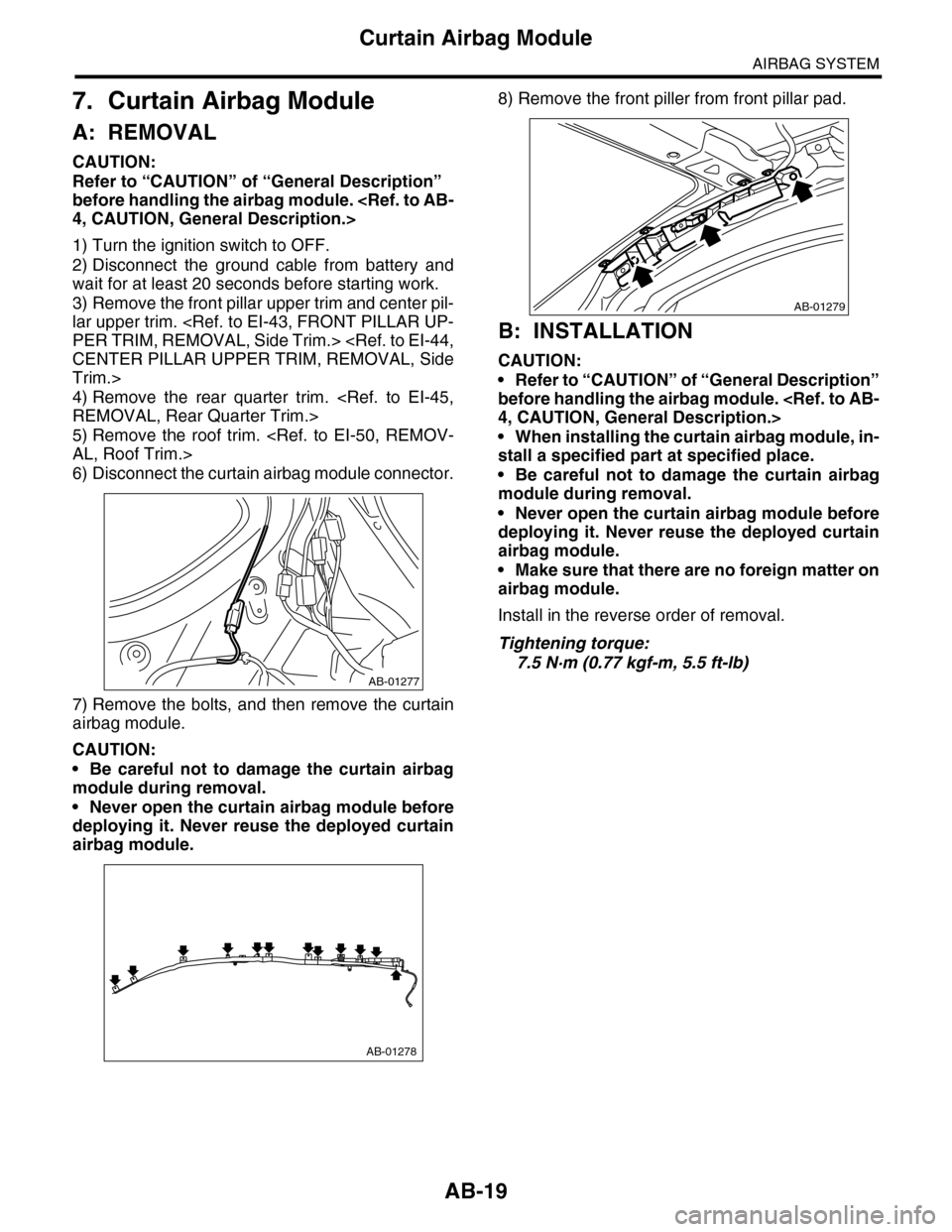
6) Disconnect the curtain airbag module connector.
7) Remove the bolts, and then remove the curtain
airbag module.
CAUTION:
•Be careful not to damage the curtain airbag
module during removal.
•Never open the curtain airbag module before
deploying it. Never reuse the deployed curtain
airbag module.
8) Remove the front piller from front pillar pad.
B: INSTALLATION
CAUTION:
•Refer to “CAUTION” of “General Description”
before handling the airbag module.
•When installing the curtain airbag module, in-
stall a specified part at specified place.
•Be careful not to damage the curtain airbag
module during removal.
•Never open the curtain airbag module before
deploying it. Never reuse the deployed curtain
airbag module.
•Make sure that there are no foreign matter on
airbag module.
Install in the reverse order of removal.
Tightening torque:
7.5 N·m (0.77 kgf-m, 5.5 ft-lb)
AB-01277
AB-01278
AB-01279
Page 20 of 2453
AB-21
Airbag Control Module
AIRBAG SYSTEM
8. Airbag Control Module
A: REMOVAL
CAUTION:
•Do not disassemble the airbag control mod-
ule.
•If the airbag control module is deformed or if
the fault occurs by water, replace the airbag
control module with a new one.
•Do not drop the airbag control module.
•After removal, keep the airbag control mod-
ule on a dry, clean surface away from moisture,
heat and dust.
1) Turn the ignition switch to OFF.
2) Disconnect the ground cable from battery and
wait for at least 20 seconds before starting work.
3) Remove the center console.
4) Remove the console box.
5) Remove the instrument panel lower cover.
er.>
6) Remove the glove box.
7) Remove the audio unit.
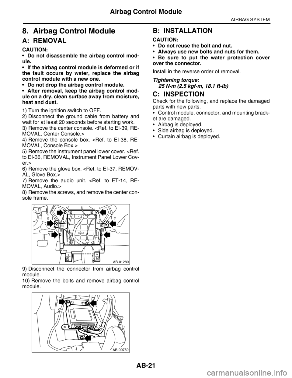
8) Remove the screws, and remove the center con-
sole frame.
9) Disconnect the connector from airbag control
module.
10) Remove the bolts and remove airbag control
module.
B: INSTALLATION
CAUTION:
•Do not reuse the bolt and nut.
•Always use new bolts and nuts for them.
•Be sure to put the water protection cover
over the connector.
Install in the reverse order of removal.
Tightening torque:
25 N·m (2.5 kgf-m, 18.1 ft-lb)
C: INSPECTION
Check for the following, and replace the damaged
parts with new parts.
•Control module, connector, and mounting brack-
et are damaged.
•Airbag is deployed.
•Side airbag is deployed.
•Curtain airbag is deployed.
AB-01280
AB-00759
Page 21 of 2453
AB-22
Side Airbag Sensor
AIRBAG SYSTEM
9. Side Airbag Sensor
A: REMOVAL
1) Turn the ignition switch to OFF.
2) Disconnect the ground cable from battery and
wait for at least 20 seconds before starting work.
3) Remove the center pillar lower trim.
Side Trim.>
4) Remove the seat belt retractor of the front outer
seat belt.
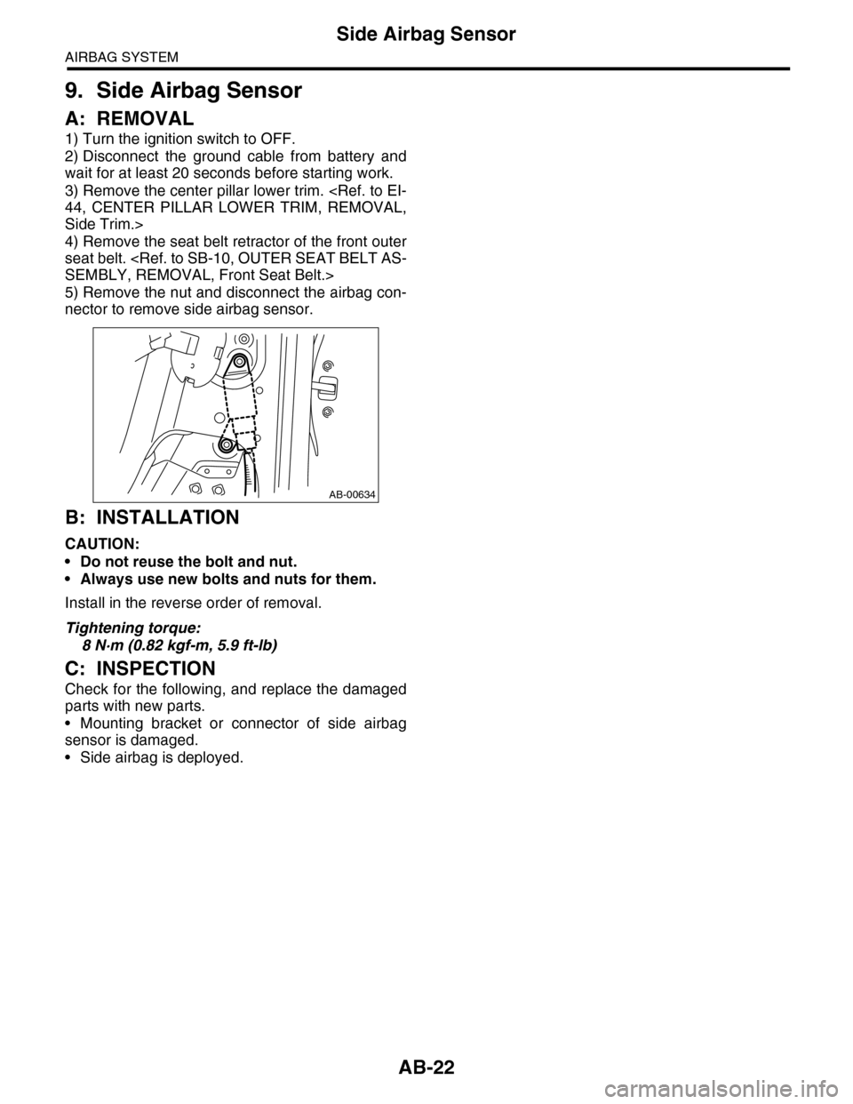
5) Remove the nut and disconnect the airbag con-
nector to remove side airbag sensor.
B: INSTALLATION
CAUTION:
•Do not reuse the bolt and nut.
•Always use new bolts and nuts for them.
Install in the reverse order of removal.
Tightening torque:
8 N·m (0.82 kgf-m, 5.9 ft-lb)
C: INSPECTION
Check for the following, and replace the damaged
parts with new parts.
•Mounting bracket or connector of side airbag
sensor is damaged.
•Side airbag is deployed.
AB-00634
Page 22 of 2453
AB-23
Curtain Airbag Sensor
AIRBAG SYSTEM
10.Curtain Airbag Sensor
A: REMOVAL
1) Turn the ignition switch to OFF.
2) Disconnect the ground cable from battery and
wait for at least 20 seconds before starting work.
3) Remove the rear quarter lower trim.
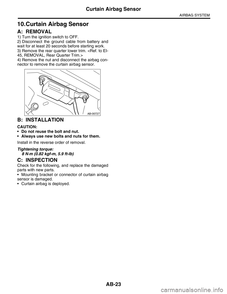
4) Remove the nut and disconnect the airbag con-
nector to remove the curtain airbag sensor.
B: INSTALLATION
CAUTION:
•Do not reuse the bolt and nut.
•Always use new bolts and nuts for them.
Install in the reverse order of removal.
Tightening torque:
8 N·m (0.82 kgf-m, 5.9 ft-lb)
C: INSPECTION
Check for the following, and replace the damaged
parts with new parts.
•Mounting bracket or connector of curtain airbag
sensor is damaged.
•Curtain airbag is deployed.
AB-00727
Page 23 of 2453
AB-24
Roll Connector
AIRBAG SYSTEM
11.Roll Connector
A: REMOVAL
1) Turn the ignition switch to OFF.
2) Disconnect the ground cable from battery and
wait for at least 20 seconds before starting work.
3) Remove the driver’s airbag module.
4) Remove the steering wheel.
5) Remove the steering column cover.
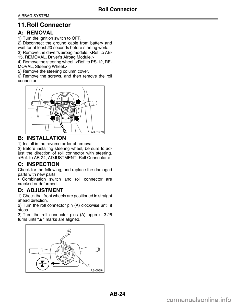
6) Remove the screws, and then remove the roll
connector.
B: INSTALLATION
1) Install in the reverse order of removal.
2) Before installing steering wheel, be sure to ad-
just the direction of roll connector with steering.
C: INSPECTION
Check for the following, and replace the damaged
parts with new parts.
•Combination switch and roll connector are
cracked or deformed.
D: ADJUSTMENT
1) Check that front wheels are positioned in straight
ahead direction.
2) Turn the roll connector pin (A) clockwise until it
stops.
3) Turn the roll connector pins (A) approx. 3.25
turns until “ ” marks are aligned.
AB-01273
AB-00594
(A)
Page 24 of 2453
AB-25
Front Sub Sensor
AIRBAG SYSTEM
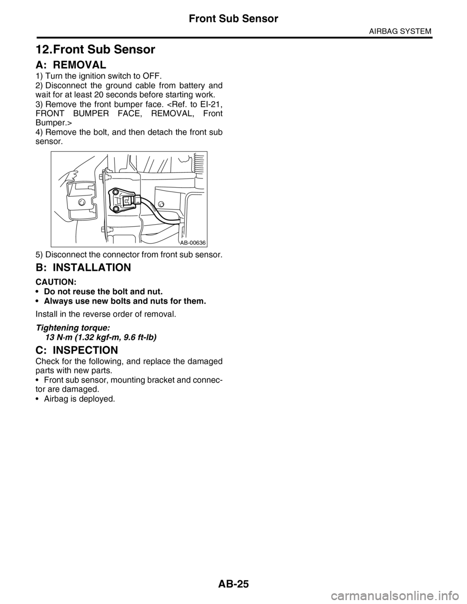
12.Front Sub Sensor
A: REMOVAL
1) Turn the ignition switch to OFF.
2) Disconnect the ground cable from battery and
wait for at least 20 seconds before starting work.
3) Remove the front bumper face.
Bumper.>
4) Remove the bolt, and then detach the front sub
sensor.
5) Disconnect the connector from front sub sensor.
B: INSTALLATION
CAUTION:
•Do not reuse the bolt and nut.
•Always use new bolts and nuts for them.
Install in the reverse order of removal.
Tightening torque:
13 N·m (1.32 kgf-m, 9.6 ft-lb)
C: INSPECTION
Check for the following, and replace the damaged
parts with new parts.
•Front sub sensor, mounting bracket and connec-
tor are damaged.
•Airbag is deployed.
AB-00636
Page 26 of 2453
AB(diag)-2
Basic Diagnostic Procedure
AIRBAG SYSTEM (DIAGNOSTICS)
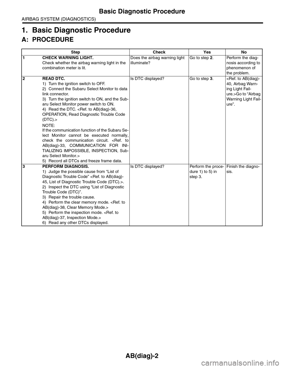
1. Basic Diagnostic Procedure
A: PROCEDURE
Step Check Yes No
1CHECK WARNING LIGHT.
Check whether the airbag warning light in the
combination meter is lit.
Does the airbag warning light
illuminate?
Go to step 2.Perform the diag-
nosis according to
phenomenon of
the problem.
2READ DTC.
1) Turn the ignition switch to OFF.
2) Connect the Subaru Select Monitor to data
link connector.
3) Turn the ignition switch to ON, and the Sub-
aru Select Monitor power switch to ON.
4) Read the DTC.
(DTC).>
NOTE:If the communication function of the Subaru Se-
lect Monitor cannot be executed normally,
check the communication circuit.
TIALIZING IMPOSSIBLE, INSPECTION, Sub-
aru Select Monitor.>
5) Record all DTCs and freeze frame data.
Is DTC displayed? Go to step 3.
ing Light Fail-
ure.>Go to “Airbag
Wa r ni n g L ig h t Fa i l-
ure”.
3PERFORM DIAGNOSIS.
1) Judge the possible cause from “List of
Diagnostic Trouble Code”
2) Inspect the DTC using “List of Diagnostic
Tr o u b l e C o d e ( D T C ) ” .
3) Repair the trouble cause.
4) Perform the clear memory mode.
5) Perform the inspection mode.
6) Read any other DTCs displayed.
Is DTC displayed? Perform the proce-
dure 1) to 5) in
step 3.
Finish the diagno-
sis.