transmission oil SUBARU TRIBECA 2009 1.G Service Repair Manual
[x] Cancel search | Manufacturer: SUBARU, Model Year: 2009, Model line: TRIBECA, Model: SUBARU TRIBECA 2009 1.GPages: 2453, PDF Size: 46.32 MB
Page 2095 of 2453
5AT-79
Oil Pump Cover
AUTOMATIC TRANSMISSION
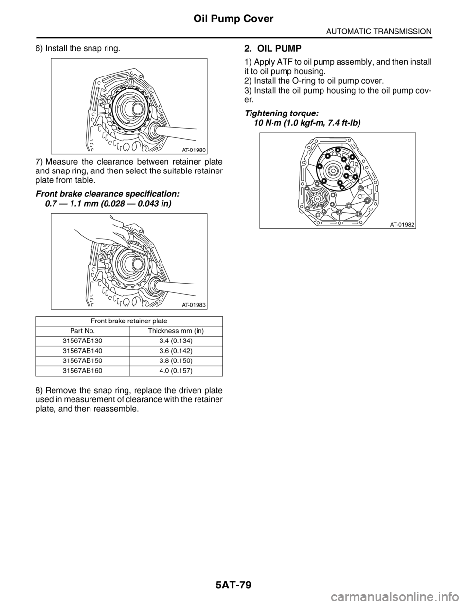
6) Install the snap ring.
7) Measure the clearance between retainer plate
and snap ring, and then select the suitable retainer
plate from table.
Front brake clearance specification:
0.7 — 1.1 mm (0.028 — 0.043 in)
8) Remove the snap ring, replace the driven plate
used in measurement of clearance with the retainer
plate, and then reassemble.
2. OIL PUMP
1) Apply ATF to oil pump assembly, and then install
it to oil pump housing.
2) Install the O-ring to oil pump cover.
3) Install the oil pump housing to the oil pump cov-
er.
Tightening torque:
10 N·m (1.0 kgf-m, 7.4 ft-lb)
Front brake retainer plate
Par t No. Thickness mm (in)
31567AB130 3.4 (0.134)
31567AB140 3.6 (0.142)
31567AB150 3.8 (0.150)
31567AB160 4.0 (0.157)
AT-01980
AT-01983
AT-01982
Page 2096 of 2453
5AT-80
Oil Pump Cover
AUTOMATIC TRANSMISSION
E: INSPECTION
1. FRONT BRAKE
Check the following items.
•Drive plate facing for wear and damage
•Snap ring for wear, return spring for damage,
and retainer for damage
•Piston for damage
•D-ring for damage
2. OIL PUMP
Check the following items.
•Oil pump cover and oil seal for breakage or dam-
age
•Oil pump body for scratch or damage
1) Check the seal ring and oil seal for breaks and
damage.
2) Check other parts for dents or faults.
3) Oil pump rotor assembly selection
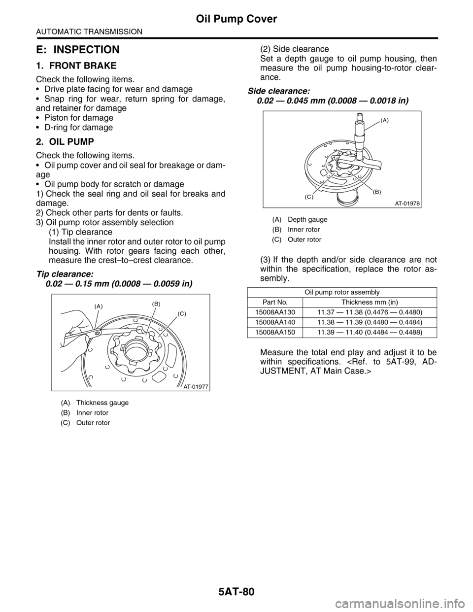
(1) Tip clearance
Install the inner rotor and outer rotor to oil pump
housing. With rotor gears facing each other,
measure the crest–to–crest clearance.
Tip clearance:
0.02 — 0.15 mm (0.0008 — 0.0059 in)
(2) Side clearance
Set a depth gauge to oil pump housing, then
measure the oil pump housing-to-rotor clear-
ance.
Side clearance:
0.02 — 0.045 mm (0.0008 — 0.0018 in)
(3) If the depth and/or side clearance are not
within the specification, replace the rotor as-
sembly.
Measure the total end play and adjust it to be
within specifications.
(A) Thickness gauge
(B) Inner rotor
(C) Outer rotor
AT-01977
(A)(B)
(C)
(A) Depth gauge
(B) Inner rotor
(C) Outer rotor
Oil pump rotor assembly
Par t No. Thickness mm (in)
15008AA130 11.37 — 11.38 (0.4476 — 0.4480)
15008AA140 11.38 — 11.39 (0.4480 — 0.4484)
15008AA150 11.39 — 11.40 (0.4484 — 0.4488)
AT-01978
(A)
(C)(B)
Page 2097 of 2453
5AT-81
Drive Pinion Shaft Assembly
AUTOMATIC TRANSMISSION
32.Drive Pinion Shaft Assembly
A: REMOVAL
1) Remove the transmission assembly from vehicle
body.
2) Pull out the torque converter assembly.
3) Remove the transmission harness connector
from stay.
4) Disconnect the air breather hose.
5) Remove the oil charge pipe.
6) Remove the ATF filter inlet and outlet pipes.
7) Separate the converter case and transmission
case.
8) Remove the drive pinion shaft mounting bolts,
and then remove the drive pinion shaft assembly
from oil pump cover.
9) Remove the oil pump cover from AT main case.
B: INSTALLATION
1) Assemble the drive pinion assembly to oil pump
cover.
NOTE:
Be careful not to bend the shim.
Tightening torque:
70 N·m (7.1 kgf-m, 51.6 ft-lb)
2) Adjust the tooth contact between drive pinion
shaft assembly and the front differential side gear.
3) Join the converter case with the transmission
case.
4) Install the transmission harness connector to the
stay.
5) Install the ATF filter pipe.
6) Install the oil charge pipe with O-ring.
7) Install the torque converter assembly.
sembly.>
8) Install the transmission assembly to the vehicle.
C: DISASSEMBLY
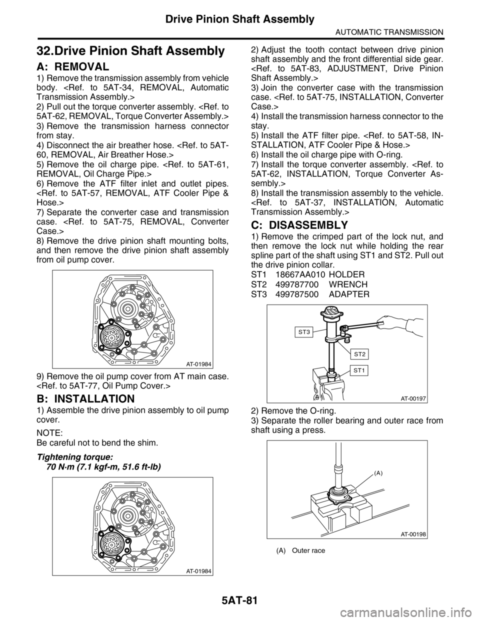
1) Remove the crimped part of the lock nut, and
then remove the lock nut while holding the rear
spline part of the shaft using ST1 and ST2. Pull out
the drive pinion collar.
ST1 18667AA010 HOLDER
ST2 499787700 WRENCH
ST3 499787500 ADAPTER
2) Remove the O-ring.
3) Separate the roller bearing and outer race from
shaft using a press.
AT-01984
AT-01984
(A) Outer race
AT-00197
ST1
ST3
ST2
AT-00198
(A)
Page 2099 of 2453
5AT-83
Drive Pinion Shaft Assembly
AUTOMATIC TRANSMISSION
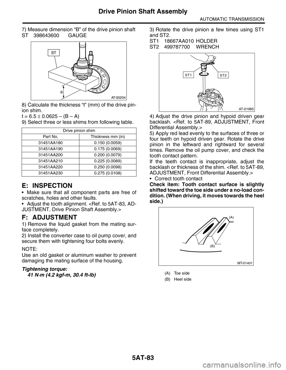
7) Measure dimension “B” of the drive pinion shaft
ST 398643600 GAUGE
8) Calculate the thickness “t” (mm) of the drive pin-
ion shim.
t = 6.5 ± 0.0625 – (B – A)
9) Select three or less shims from following table.
E: INSPECTION
•Make sure that all component parts are free of
scratches, holes and other faults.
•Adjust the tooth alignment.
F: ADJUSTMENT
1) Remove the liquid gasket from the mating sur-
face completely.
2) Install the converter case to oil pump cover, and
secure them with tightening four bolts evenly.
NOTE:
Use an old gasket or aluminum washer to prevent
damaging the mating surface of the housing.
Tightening torque:
41 N·m (4.2 kgf-m, 30.4 ft-lb)
3) Rotate the drive pinion a few times using ST1
and ST2.
ST1 18667AA010 HOLDER
ST2 499787700 WRENCH
4) Adjust the drive pinion and hypoid driven gear
backlash.
5) Apply red lead evenly to the surfaces of three or
four teeth on hypoid driven gear. Rotate the drive
pinion in the leftward and rightward for several
times. Remove the oil pump cover, and check the
tooth contact pattern.
If the teeth contact is inappropriate, adjust the
backlash or thickness of the shim.
•Correct tooth contact
Check item: Tooth contact surface is slightly
shifted toward the toe side under a no-load con-
dition. (When driving, it moves towards the heel
side.)
Drive pinion shim
Par t No. Thickness mm (in)
31451AA180 0.150 (0.0059)
31451AA190 0.175 (0.0069)
31451AA200 0.200 (0.0079)
31451AA210 0.225 (0.0089)
31451AA220 0.250 (0.0098)
31451AA230 0.275 (0.0108)
B
AT-00204
(A) Toe side
(B) Heel side
AT-01985
ST2ST1
MT-01401
(A)
(B)
Page 2101 of 2453
5AT-85
Drive Pinion Shaft Assembly
AUTOMATIC TRANSMISSION
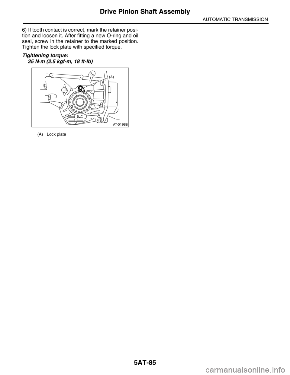
6) If tooth contact is correct, mark the retainer posi-
tion and loosen it. After fitting a new O-ring and oil
seal, screw in the retainer to the marked position.
Tighten the lock plate with specified torque.
Tightening torque:
25 N·m (2.5 kgf-m, 18 ft-lb)
(A) Lock plate
AT-01988
(A)
Page 2102 of 2453
5AT-86
Front Differential Assembly
AUTOMATIC TRANSMISSION
33.Front Differential Assembly
A: REMOVAL
1) Remove the transmission assembly from vehicle
body.
2) Pull out the torque converter assembly.
3) Remove the transmission harness connector
from stay.
4) Remove the oil charge pipe.
5) Remove the ATF filter inlet and outlet pipes.
6) Separate the converter case from the transmis-
sion case.
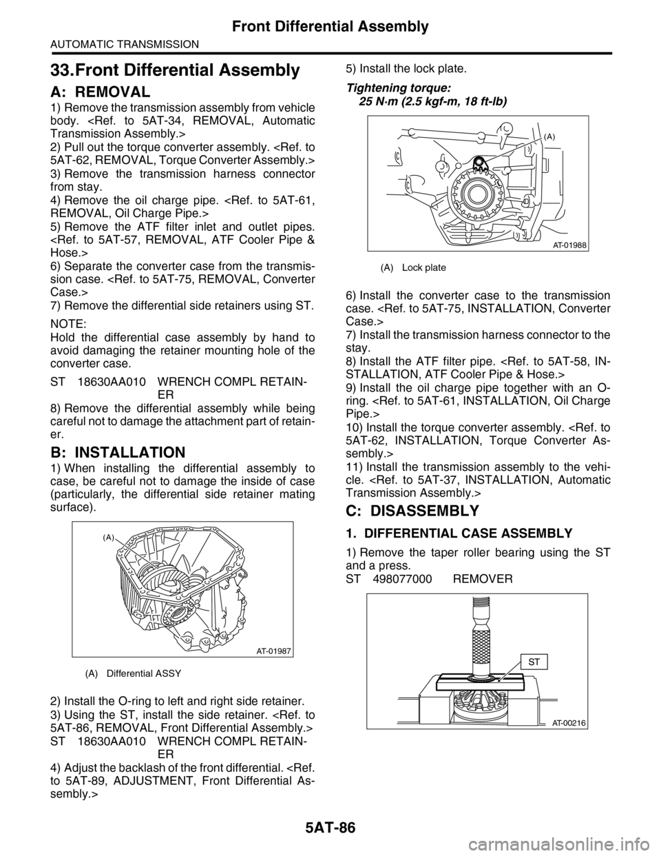
7) Remove the differential side retainers using ST.
NOTE:
Hold the differential case assembly by hand to
avoid damaging the retainer mounting hole of the
converter case.
ST 18630AA010 WRENCH COMPL RETAIN-
ER
8) Remove the differential assembly while being
careful not to damage the attachment part of retain-
er.
B: INSTALLATION
1) When installing the differential assembly to
case, be careful not to damage the inside of case
(particularly, the differential side retainer mating
surface).
2) Install the O-ring to left and right side retainer.
3) Using the ST, install the side retainer.
ST 18630AA010 WRENCH COMPL RETAIN-
ER
4) Adjust the backlash of the front differential.
sembly.>
5) Install the lock plate.
Tightening torque:
25 N·m (2.5 kgf-m, 18 ft-lb)
6) Install the converter case to the transmission
case.
7) Install the transmission harness connector to the
stay.
8) Install the ATF filter pipe.
9) Install the oil charge pipe together with an O-
ring.
10) Install the torque converter assembly.
sembly.>
11) Install the transmission assembly to the vehi-
cle.
C: DISASSEMBLY
1. DIFFERENTIAL CASE ASSEMBLY
1) Remove the taper roller bearing using the ST
and a press.
ST 498077000 REMOVER
(A) Differential ASSY
AT-01987
(A)
(A) Lock plate
AT-01988
(A)
AT-00216
Page 2103 of 2453
5AT-87
Front Differential Assembly
AUTOMATIC TRANSMISSION
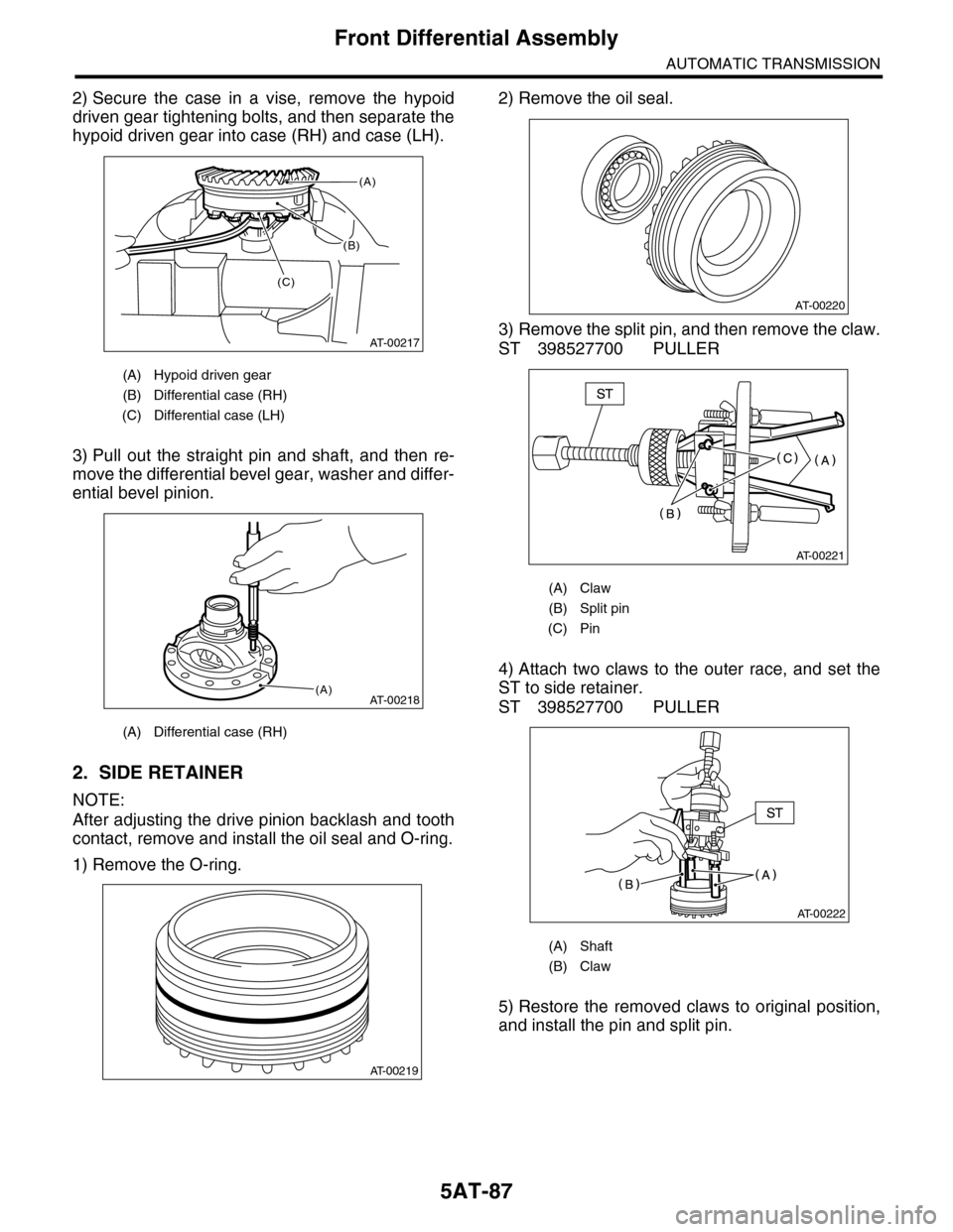
2) Secure the case in a vise, remove the hypoid
driven gear tightening bolts, and then separate the
hypoid driven gear into case (RH) and case (LH).
3) Pull out the straight pin and shaft, and then re-
move the differential bevel gear, washer and differ-
ential bevel pinion.
2. SIDE RETAINER
NOTE:
After adjusting the drive pinion backlash and tooth
contact, remove and install the oil seal and O-ring.
1) Remove the O-ring.
2) Remove the oil seal.
3) Remove the split pin, and then remove the claw.
ST 398527700 PULLER
4) Attach two claws to the outer race, and set the
ST to side retainer.
ST 398527700 PULLER
5) Restore the removed claws to original position,
and install the pin and split pin.
(A) Hypoid driven gear
(B) Differential case (RH)
(C) Differential case (LH)
(A) Differential case (RH)
(B)
AT-00217
(A)
(C)
AT-00218(A)
AT-00219
(A) Claw
(B) Split pin
(C) Pin
(A) Shaft
(B) Claw
AT-00220
AT-00221
AT-00222
Page 2105 of 2453
5AT-89
Front Differential Assembly
AUTOMATIC TRANSMISSION
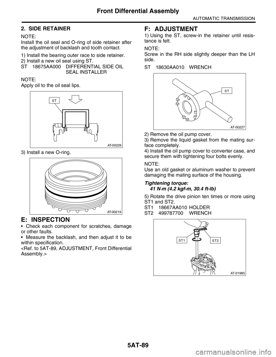
2. SIDE RETAINER
NOTE:
Install the oil seal and O-ring of side retainer after
the adjustment of backlash and tooth contact.
1) Install the bearing outer race to side retainer.
2) Install a new oil seal using ST.
ST 18675AA000 DIFFERENTIAL SIDE OIL
SEAL INSTALLER
NOTE:
Apply oil to the oil seal lips.
3) Install a new O-ring.
E: INSPECTION
•Check each component for scratches, damage
or other faults.
•Measure the backlash, and then adjust it to be
within specification.
F: ADJUSTMENT
1) Using the ST, screw-in the retainer until resis-
tance is felt.
NOTE:
Screw in the RH side slightly deeper than the LH
side.
ST 18630AA010 WRENCH
2) Remove the oil pump cover.
3) Remove the liquid gasket from the mating sur-
face completely.
4) Install the oil pump cover to converter case, and
secure them with tightening four bolts evenly.
NOTE:
Use an old gasket or aluminum washer to prevent
damaging the mating surface of the housing.
Tightening torque:
41 N·m (4.2 kgf-m, 30.4 ft-lb)
5) Rotate the drive pinion ten times or more using
ST1 and ST2.
ST1 18667AA010 HOLDER
ST2 499787700 WRENCH
AT-00226
ST
AT-00219
AT-00227
ST
AT-01985
ST2ST1
Page 2107 of 2453
5AT-91
AT Main Case
AUTOMATIC TRANSMISSION
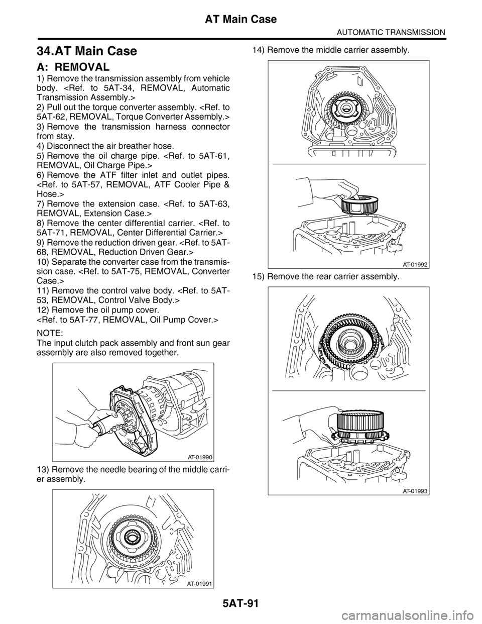
34.AT Main Case
A: REMOVAL
1) Remove the transmission assembly from vehicle
body.
2) Pull out the torque converter assembly.
3) Remove the transmission harness connector
from stay.
4) Disconnect the air breather hose.
5) Remove the oil charge pipe.
6) Remove the ATF filter inlet and outlet pipes.
7) Remove the extension case.
8) Remove the center differential carrier.
9) Remove the reduction driven gear.
10) Separate the converter case from the transmis-
sion case.
11) Remove the control valve body.
12) Remove the oil pump cover.
NOTE:
The input clutch pack assembly and front sun gear
assembly are also removed together.
13) Remove the needle bearing of the middle carri-
er assembly.
14) Remove the middle carrier assembly.
15) Remove the rear carrier assembly.
AT-01990
AT-01991
AT-01992
AT-01993
Page 2112 of 2453
5AT-96
AT Main Case
AUTOMATIC TRANSMISSION
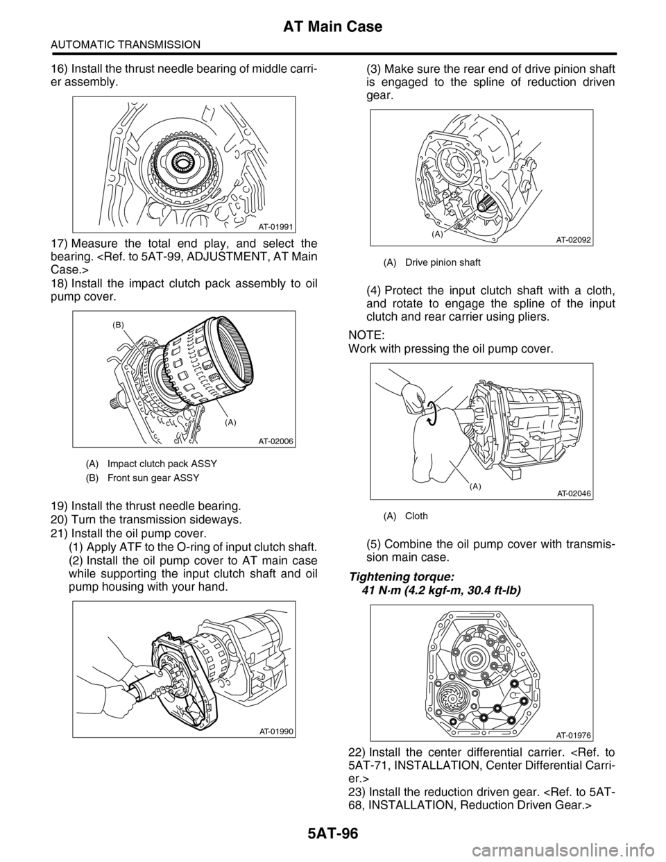
16) Install the thrust needle bearing of middle carri-
er assembly.
17) Measure the total end play, and select the
bearing.
18) Install the impact clutch pack assembly to oil
pump cover.
19) Install the thrust needle bearing.
20) Turn the transmission sideways.
21) Install the oil pump cover.
(1) Apply ATF to the O-ring of input clutch shaft.
(2) Install the oil pump cover to AT main case
while supporting the input clutch shaft and oil
pump housing with your hand.
(3) Make sure the rear end of drive pinion shaft
is engaged to the spline of reduction driven
gear.
(4) Protect the input clutch shaft with a cloth,
and rotate to engage the spline of the input
clutch and rear carrier using pliers.
NOTE:
Work with pressing the oil pump cover.
(5) Combine the oil pump cover with transmis-
sion main case.
Tightening torque:
41 N·m (4.2 kgf-m, 30.4 ft-lb)
22) Install the center differential carrier.
er.>
23) Install the reduction driven gear.
(A) Impact clutch pack ASSY
(B) Front sun gear ASSY
AT-01991
AT-02006
(A)
(B)
AT-01990
(A) Drive pinion shaft
(A) Cloth
AT-02092(A)
AT-02046(A)
AT-01976