ATF temp sensor SUBARU TRIBECA 2009 1.G Service Workshop Manual
[x] Cancel search | Manufacturer: SUBARU, Model Year: 2009, Model line: TRIBECA, Model: SUBARU TRIBECA 2009 1.GPages: 2453, PDF Size: 46.32 MB
Page 1135 of 2453
CO(H6DO)-16
Radiator
COOLING
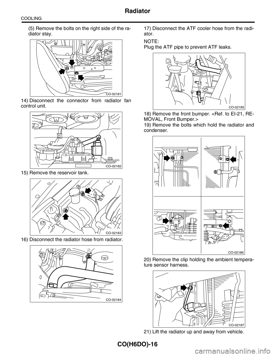
(5) Remove the bolts on the right side of the ra-
diator stay.
14) Disconnect the connector from radiator fan
control unit.
15) Remove the reservoir tank.
16) Disconnect the radiator hose from radiator.
17) Disconnect the ATF cooler hose from the radi-
ator.
NOTE:
Plug the ATF pipe to prevent ATF leaks.
18) Remove the front bumper.
19) Remove the bolts which hold the radiator and
condenser.
20) Remove the clip holding the ambient tempera-
ture sensor harness.
21) Lift the radiator up and away from vehicle.
CO-02181
CO-02182
CO-02183
CO-02184
CO-02185
CO-02186
CO-02187
Page 1136 of 2453
CO(H6DO)-17
Radiator
COOLING
B: INSTALLATION
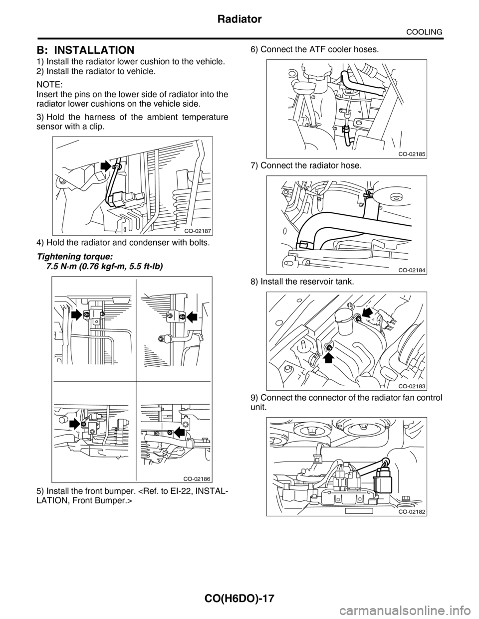
1) Install the radiator lower cushion to the vehicle.
2) Install the radiator to vehicle.
NOTE:
Insert the pins on the lower side of radiator into the
radiator lower cushions on the vehicle side.
3) Hold the harness of the ambient temperature
sensor with a clip.
4) Hold the radiator and condenser with bolts.
Tightening torque:
7.5 N·m (0.76 kgf-m, 5.5 ft-lb)
5) Install the front bumper.
6) Connect the ATF cooler hoses.
7) Connect the radiator hose.
8) Install the reservoir tank.
9) Connect the connector of the radiator fan control
unit.
CO-02187
CO-02186
CO-02185
CO-02184
CO-02183
CO-02182
Page 2125 of 2453
5AT(diag)-8
Electrical Component Location
AUTOMATIC TRANSMISSION (DIAGNOSTICS)
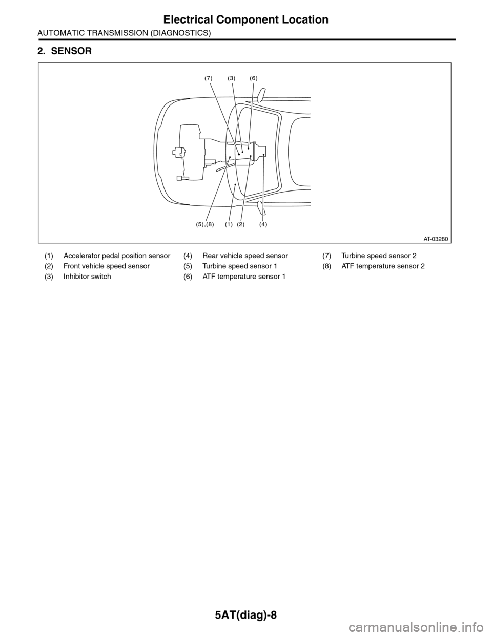
2. SENSOR
(1) Accelerator pedal position sensor (4) Rear vehicle speed sensor (7) Turbine speed sensor 2
(2) Front vehicle speed sensor (5) Turbine speed sensor 1 (8) ATF temperature sensor 2
(3) Inhibitor switch (6) ATF temperature sensor 1
AT-03280
(3) (6)
(5),(8) (2) (4)
(7)
(1)
Page 2129 of 2453
5AT(diag)-12
Transmission Control Module (TCM) I/O Signal
AUTOMATIC TRANSMISSION (DIAGNOSTICS)
I/C solenoid output B54 18
While driving at 1st —
3rd of manual mode
Approx. 5.5 —
7.5 V3 — 9 Ω (ATF
temperature
20°C (68°F))
Driving fre-
quency 750 —
850 HzWhile driving at 4th or
5th of manual modeApprox. 0 V
H & LR/C solenoid
outputB54 17
While driving at 2nd of
manual mode
Approx. 5.5 —
7.5 V3 — 9 Ω (ATF
temperature
20°C (68°F))
Driving fre-
quency 750 —
850 HzWhile driving at 3rd —
5th of manual modeApprox. 0 V
Control valve power
supply outputB54 16Ignition switch ONPow er s up p ly
voltage—
Ignition switch OFF Approx. 0 V
LC/B solenoid output B54 15
While driving at 1st —
2nd of manual mode
Pow er s up p ly
voltage5 — 17 Ω (ATF
temperature
25°C (77°F))
While driving at 3rd —
5th of manual modeApprox. 0 V
Pow er GN D B 5 4 1 4 A lways A pp r ox . 0 V —
Analog GND (sensor
GND)B54 13 Always Approx. 0 V —
LC/B oil pressure
switch inputB54 12 — — —
The condition
of LC/B oil
pressure switch
cannot be read
by the tester.
AT F t e m p e r a t u r e s e n -
sor 2 inputB54 11 Ignition switch ON
2.3 — 2.7 V
(ATF tempera-
ture 20°C
(68°F))
0.6 — 0.8 V
(ATF tempera-
ture 80°C
(176°F))
3.0 — 3.6 kΩ
(ATF tempera-
ture 20°C
(68°F))
0.4 — 0.6 kΩ
(ATF tempera-
ture 80°C
(176°F))
PVIGN power supply
relay outputB54 10 Ignition switch ON 0 — 1.5 V —
Fr / B so le n oi d o u tp u t B 5 4 2 4
While driving at other
than 4th of manual
mode
Approx. 4.5 —
6.5 V3 — 9 Ω (ATF
temperature
20°C (68°F))
Driving fre-
quency 750 —
850 HzWhile driving at 4th of
manual modeApprox. 0 V
L/U solenoid output B54 23When lock-upApprox. 3.5 —
5.5 V3 — 9 Ω (ATF
temperature
20°C (68°F))
Driving fre-
quency 750 —
850 HzWhen not lock-up Approx. 0 V
D/C solenoid output B54 22
While driving at 1st or
5th of manual mode
Approx. 5.5 —
7.5 V3 — 9 Ω (ATF
temperature
20°C (68°F))
Driving fre-
quency 750 —
850 HzWhile driving at 2nd —
4th of manual modeApprox. 0 V
D/C oil pressure
switch inputB54 21 — — —
The condition
of D/C oil pres-
sure switch
cannot be read
by the tester.
Subaru Select Moni-
tor communication
line
B54 20 — — —
Control GND B54 19 Always Approx. 0 V —
ItemConnector
No.
Te r m i n a l
No.Measuring condition Measured value
Resistance
between termi-
nal and chassis
ground
Remarks
Page 2131 of 2453
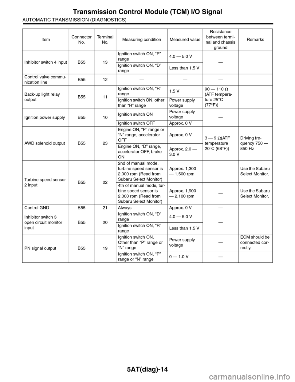
5AT(diag)-14
Transmission Control Module (TCM) I/O Signal
AUTOMATIC TRANSMISSION (DIAGNOSTICS)
Inhibitor switch 4 input B55 13
Ignition switch ON, “P”
range4.0 — 5.0 V
—
Ignition switch ON, “D”
rangeLess than 1.5 V
Control valve commu-
nication lineB55 12 — — —
Back-up light relay
outputB55 11
Ignition switch ON, “R”
range1.5 V90 — 110 Ω
(ATF tempera-
ture 25°C
(77°F))
Ignition switch ON, other
than “R” range
Pow er s up p ly
voltage
Ignition power supply B55 10Ignition switch ONPow er s up p ly
voltage—
Ignition switch OFF Approx. 0 V
AW D s o le n oi d o u tp u t B 5 5 2 3
Engine ON, “P” range or
“N” range, accelerator
OFF
Approx. 0 V3 — 9 Ω(ATF
temperature
20°C (68°F))
Driving fre-
quency 750 —
850 HzEngine ON, “D” range,
accelerator OFF, brake
ON
Approx. 2.0 —
3.0 V
Tu r b i n e s p e e d s e n s o r
2 inputB55 22
2nd of manual mode,
turbine speed sensor is
2,000 rpm (Read from
Subaru Select Monitor)
Approx. 1,300
— 1,500 rpm
Use the Subaru
Select Monitor.
4th of manual mode, tur-
bine speed sensor is
2,000 rpm (Read from
Subaru Select Monitor)
Approx. 1,900
— 2,100 rpm—Use the Subaru
Select Monitor.
Control GND B55 21 Always Approx. 0 V —
Inhibitor switch 3
open circuit monitor
input
B55 20
Ignition switch ON, “D”
range4.0 — 5.0 V
—
Ignition switch ON, “R”
rangeLess than 1.5 V
PN signal output B55 19
Ignition switch ON,
Other than “P” range or
“N” range
Pow er s up p ly
voltage—
ECM should be
connected cor-
rectly.
Ignition switch ON, “P”
range or “N” range0 — 1.0 V —
ItemConnector
No.
Te r m i n a l
No.Measuring condition Measured value
Resistance
between termi-
nal and chassis
ground
Remarks
Page 2133 of 2453
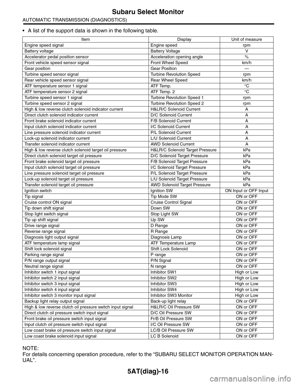
5AT(diag)-16
Subaru Select Monitor
AUTOMATIC TRANSMISSION (DIAGNOSTICS)
•A list of the support data is shown in the following table.
NOTE:
For details concerning operation procedure, refer to the “SUBARU SELECT MONITOR OPERATION MAN-
UAL”.
Item Display Unit of measure
Engine speed signal Engine speed rpm
Battery voltage Battery Voltage V
Accelerator pedal position sensor Acceleration opening angle %
Fr o nt veh ic l e sp e ed se n so r s ig n al Fr o n t W h ee l S p e ed km/ h
Gear position Gear Position —
Tu r b i n e s p e e d s e n s o r s i g n a l Tu r b i n e R e v o l u t i o n S p e e d r p m
Rear vehicle speed sensor signal Rear Wheel Speed km/h
ATF temperature sensor 1 signal ATF Temp. °C
ATF temperature sensor 2 signal ATF Temp. 2 °C
Tu r b i n e s p e e d s e n s o r 1 s i g n a l Tu r b i n e R e v o l u t i o n S p e e d 1 r p m
Tu r b i n e s p e e d s e n s o r 2 s i g n a l Tu r b i n e R e v o l u t i o n S p e e d 2 r p m
High & low reverse clutch solenoid indicator current H&LR/C Solenoid Current A
Direct clutch solenoid indicator current D/C Solenoid Current A
Fr o nt b rake so l en oi d in di c at o r c u rr e n t F / B S o l en o id Cur r e nt A
Input clutch solenoid indicator current I/C Solenoid Current A
Line pressure solenoid indicator current P/L Solenoid Current A
Lock-up solenoid indicator current L/U Solenoid Current A
Tr a n s f e r s o l e n o i d i n d i c a t o r c u r r e n t A W D S o l e n o i d C u r r e n t A
High & low reverse clutch solenoid target oil pressure H&LR/C Solenoid Target Pressure kPa
Direct clutch solenoid target oil pressure D/C Solenoid Target Pressure kPa
Fr o nt b rake so l en oi d ta r g et o il pr e ss ur e F / B S o l en o id Ta r g et P r es su r e kPa
Input clutch solenoid target oil pressure I/C Solenoid Target Pressure kPa
Line pressure solenoid target oil pressure P/L Solenoid Target Pressure kPa
Lock-up solenoid target oil pressure L/U Solenoid Target Pressure kPa
Tr a n s f e r s o l e n o i d t a r g e t o i l p r e s s u r e A W D S o l e n o i d Ta r g e t P r e s s u r e k P a
Ignition switch Ignition SW ON Input or OFF Input
Tip signal Tip Mode SW ON or OFF
Cruise control ON signal Cruise Control Signal ON or OFF
Tip down shift signal Down SW ON or OFF
Stop light switch signal Stop Light SW ON or OFF
Tip up shift signal Up SW ON or OFF
Drive range signal D Range ON or OFF
Reverse range signal R Range ON or OFF
Diagnosis light output signal Diagnosis Lamp ON or OFF
AT F t e m p e r a t u r e l a m p s i g n a l AT F Te m p e r a t u r e L a m p O N o r O F F
Shift lock solenoid signal Shift Lock Solenoid ON or OFF
Par king range signal P range ON or OFF
P/N range output signal P/N Signal ON or OFF
Neutral range signal N range ON or OFF
Inhibitor switch 1 input signal Inhibitor SW1 High or Low
Inhibitor switch 2 input signal Inhibitor SW2 High or Low
Inhibitor switch 3 input signal Inhibitor SW3 High or Low
Inhibitor switch 4 input signal Inhibitor SW4 High or Low
Inhibitor switch 3 monitor input signal Inhibitor SW3 Monitor High or Low
Backup light relay output signal Back-up light relay ON or OFF
High & low reverse clutch oil pressure switch input signal H&LR/C Oil Pressure SW ON or OFF
Direct clutch oil pressure switch input signal D/C Oil Pressure SW ON or OFF
Fr o nt b rake oi l pr e ss ur e swi tc h i n pu t si gn a l Fr / B Oi l P r e ss ur e S W ON or OF F
Input clutch oil pressure switch input signal I/C Oil Pressure SW ON or OFF
Low coast brake oil pressure switch input signal LC/B Oil Pressure SW ON or OFF
Low coast brake solenoid input signal LC B Solenoid ON or OFF
Page 2147 of 2453
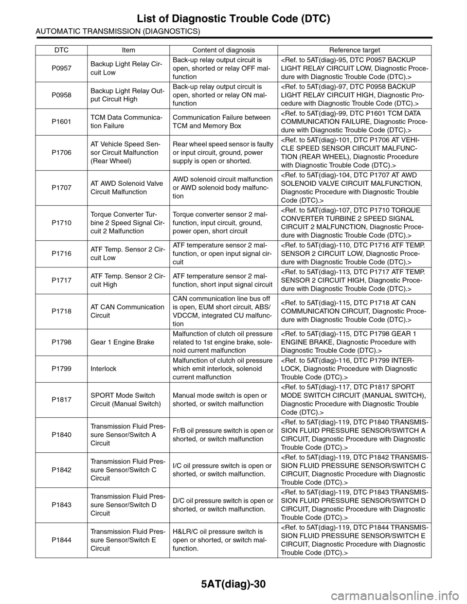
5AT(diag)-30
List of Diagnostic Trouble Code (DTC)
AUTOMATIC TRANSMISSION (DIAGNOSTICS)
P0957Backup Light Relay Cir-
cuit Low
Back-up relay output circuit is
open, shorted or relay OFF mal-
function
dure with Diagnostic Trouble Code (DTC).>
P0958Backup Light Relay Out-
put Circuit High
Back-up relay output circuit is
open, shorted or relay ON mal-
function
cedure with Diagnostic Trouble Code (DTC).>
P1601TCM Data Communica-
tion Failure
Communication Failure between
TCM and Memory Box
dure with Diagnostic Trouble Code (DTC).>
P1706
AT Ve h i c l e S p e e d S e n -
sor Circuit Malfunction
(Rear Wheel)
Rear wheel speed sensor is faulty
or input circuit, ground, power
supply is open or shorted.
TION (REAR WHEEL), Diagnostic Procedure
with Diagnostic Trouble Code (DTC).>
P1707AT A W D S o l e n o i d V a l v e
Circuit Malfunction
AWD solenoid circuit malfunction
or AWD solenoid body malfunc-
tion
Diagnostic Procedure with Diagnostic Trouble
Code (DTC).>
P1710
To r q u e C o n v e r t e r Tu r -
bine 2 Speed Signal Cir-
cuit 2 Malfunction
To r q u e c o n v e r t e r s e n s o r 2 m a l -
function, input circuit, ground,
power open, short circuit
CIRCUIT 2 MALFUNCTION, Diagnostic Proce-
dure with Diagnostic Trouble Code (DTC).>
P1716AT F Te m p . S e n s o r 2 C i r -
cuit Low
AT F t e m p e r a t u r e s e n s o r 2 m a l -
function, or open input signal cir-
cuit
dure with Diagnostic Trouble Code (DTC).>
P1717AT F Te m p . S e n s o r 2 C i r -
cuit High
AT F t e m p e r a t u r e s e n s o r 2 m a l -
function, short input signal circuit
dure with Diagnostic Trouble Code (DTC).>
P1718AT C A N C o m m u n i c a t i o n
Circuit
CAN communication line bus off
is open, EUM short circuit, ABS/
VDCCM, integrated CU malfunc-
tion
dure with Diagnostic Trouble Code (DTC).>
P1798 Gear 1 Engine Brake
Malfunction of clutch oil pressure
related to 1st engine brake, sole-
noid current malfunction
Diagnostic Trouble Code (DTC).>
P1799 Interlock
Malfunction of clutch oil pressure
which emit interlock, solenoid
current malfunction
Tr o u b l e C o d e ( D T C ) . >
P1817SPORT Mode Switch
Circuit (Manual Switch)
Manual mode switch is open or
shorted, or switch malfunction
Diagnostic Procedure with Diagnostic Trouble
Code (DTC).>
P1840
Tr a n s m i s s i o n F l u i d P r e s -
sure Sensor/Switch A
Circuit
Fr/B oil pressure switch is open or
shorted, or switch malfunction
CIRCUIT, Diagnostic Procedure with Diagnostic
Tr o u b l e C o d e ( D T C ) . >
P1842
Tr a n s m i s s i o n F l u i d P r e s -
sure Sensor/Switch C
Circuit
I/C oil pressure switch is open or
shorted, or switch malfunction.
CIRCUIT, Diagnostic Procedure with Diagnostic
Tr o u b l e C o d e ( D T C ) . >
P1843
Tr a n s m i s s i o n F l u i d P r e s -
sure Sensor/Switch D
Circuit
D/C oil pressure switch is open or
shorted, or switch malfunction.
CIRCUIT, Diagnostic Procedure with Diagnostic
Tr o u b l e C o d e ( D T C ) . >
P1844
Tr a n s m i s s i o n F l u i d P r e s -
sure Sensor/Switch E
Circuit
H&LR/C oil pressure switch is
open or shorted, or switch mal-
function.
CIRCUIT, Diagnostic Procedure with Diagnostic
Tr o u b l e C o d e ( D T C ) . >
DTC Item Content of diagnosis Reference target
Page 2152 of 2453
5AT(diag)-35
Diagnostic Procedure with Diagnostic Trouble Code (DTC)
AUTOMATIC TRANSMISSION (DIAGNOSTICS)
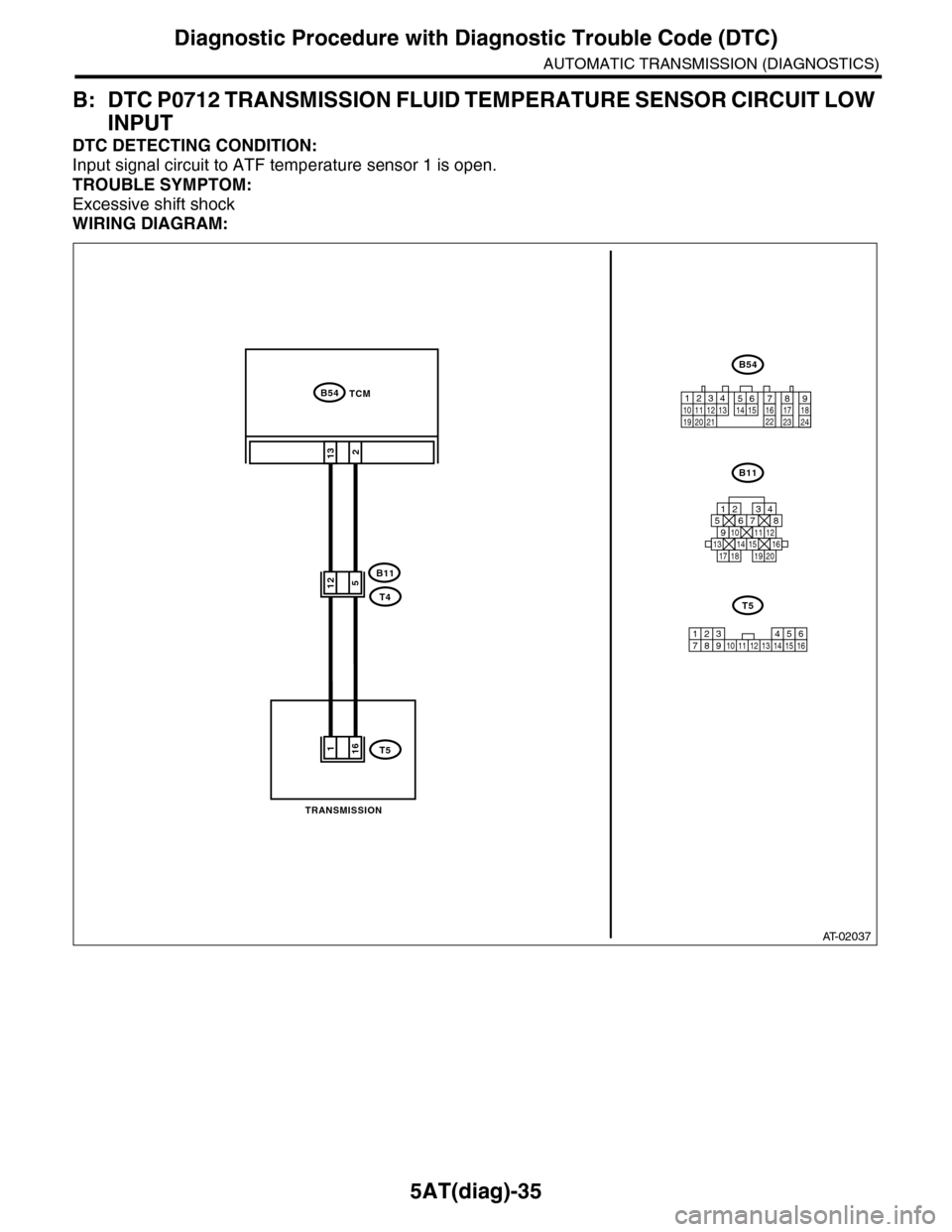
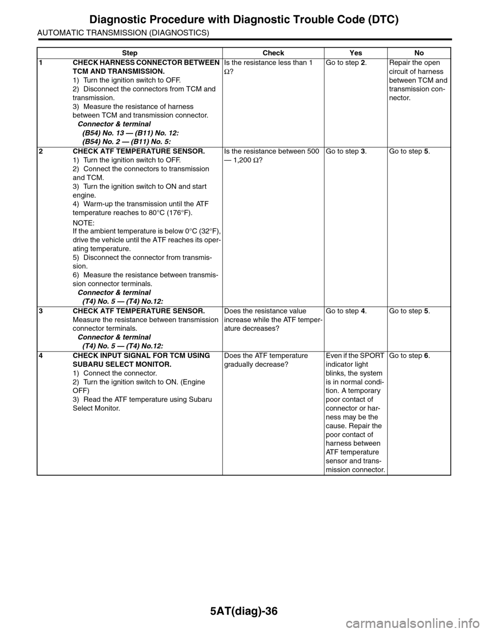
B: DTC P0712 TRANSMISSION FLUID TEMPERATURE SENSOR CIRCUIT LOW
INPUT
DTC DETECTING CONDITION:
Input signal circuit to ATF temperature sensor 1 is open.
TROUBLE SYMPTOM:
Excessive shift shock
WIRING DIAGRAM:
AT-02037
2
B54
B11
T4
T5
TCM
13
B54
B11
12789563410 11 1219 20 2113 14 15 16 17 18222324
TRANSMISSION
125678
131415169101112
34
17181920
512
161
123 68910 11 12 13 14451516
T5
7
Page 2153 of 2453
5AT(diag)-36
Diagnostic Procedure with Diagnostic Trouble Code (DTC)
AUTOMATIC TRANSMISSION (DIAGNOSTICS)
Step Check Yes No
1CHECK HARNESS CONNECTOR BETWEEN
TCM AND TRANSMISSION.
1) Turn the ignition switch to OFF.
2) Disconnect the connectors from TCM and
transmission.
3) Measure the resistance of harness
between TCM and transmission connector.
Connector & terminal
(B54) No. 13 — (B11) No. 12:
(B54) No. 2 — (B11) No. 5:
Is the resistance less than 1
Ω?
Go to step 2.Repair the open
circuit of harness
between TCM and
transmission con-
nector.
2CHECK ATF TEMPERATURE SENSOR.
1) Turn the ignition switch to OFF.
2) Connect the connectors to transmission
and TCM.
3) Turn the ignition switch to ON and start
engine.
4) Warm-up the transmission until the ATF
temperature reaches to 80°C (176°F).
NOTE:
If the ambient temperature is below 0°C (32°F),
drive the vehicle until the ATF reaches its oper-
ating temperature.
5) Disconnect the connector from transmis-
sion.
6) Measure the resistance between transmis-
sion connector terminals.
Connector & terminal
(T4) No. 5 — (T4) No.12:
Is the resistance between 500
— 1,200 Ω?
Go to step 3.Go to step 5.
3CHECK ATF TEMPERATURE SENSOR.
Measure the resistance between transmission
connector terminals.
Connector & terminal
(T4) No. 5 — (T4) No.12:
Does the resistance value
increase while the ATF temper-
ature decreases?
Go to step 4.Go to step 5.
4CHECK INPUT SIGNAL FOR TCM USING
SUBARU SELECT MONITOR.
1) Connect the connector.
2) Turn the ignition switch to ON. (Engine
OFF)
3) Read the ATF temperature using Subaru
Select Monitor.
Does the ATF temperature
gradually decrease?
Even if the SPORT
indicator light
blinks, the system
is in normal condi-
tion. A temporary
poor contact of
connector or har-
ness may be the
cause. Repair the
poor contact of
harness between
AT F t e m p e r a t u r e
sensor and trans-
mission connector.
Go to step 6.
Page 2154 of 2453
5AT(diag)-37
Diagnostic Procedure with Diagnostic Trouble Code (DTC)
AUTOMATIC TRANSMISSION (DIAGNOSTICS)
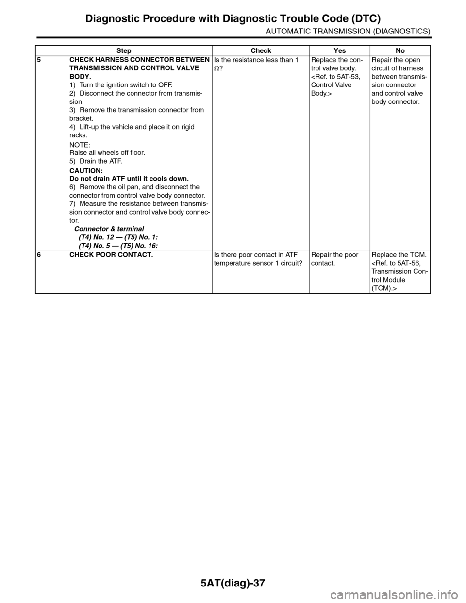
5CHECK HARNESS CONNECTOR BETWEEN
TRANSMISSION AND CONTROL VALVE
BODY.
1) Turn the ignition switch to OFF.
2) Disconnect the connector from transmis-
sion.
3) Remove the transmission connector from
bracket.
4) Lift-up the vehicle and place it on rigid
racks.
NOTE:Raise all wheels off floor.
5) Drain the ATF.
CAUTION:Do not drain ATF until it cools down.
6) Remove the oil pan, and disconnect the
connector from control valve body connector.
7) Measure the resistance between transmis-
sion connector and control valve body connec-
tor.
Connector & terminal
(T4) No. 12 — (T5) No. 1:
(T4) No. 5 — (T5) No. 16:
Is the resistance less than 1
Ω?
Replace the con-
trol valve body.
Body.>
Repair the open
circuit of harness
between transmis-
sion connector
and control valve
body connector.
6CHECK POOR CONTACT.Is there poor contact in ATF
temperature sensor 1 circuit?
Repair the poor
contact.
Replace the TCM.
trol Module
(TCM).>
Step Check Yes No