Reverse lamp SUBARU TRIBECA 2009 1.G Service Workshop Manual
[x] Cancel search | Manufacturer: SUBARU, Model Year: 2009, Model line: TRIBECA, Model: SUBARU TRIBECA 2009 1.GPages: 2453, PDF Size: 46.32 MB
Page 213 of 2453
ET-28
Rear Entertainment
ENTERTAINMENT
23.Rear Entertainment
A: REMOVAL
1) Disconnect the ground cable from battery.
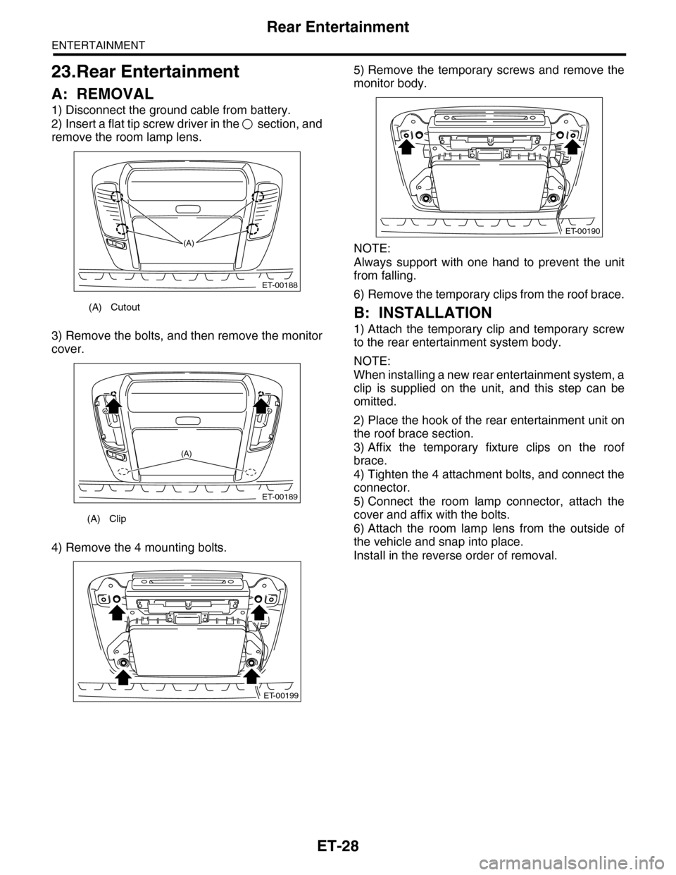
2) Insert a flat tip screw driver in the section, and
remove the room lamp lens.
3) Remove the bolts, and then remove the monitor
cover.
4) Remove the 4 mounting bolts.
5) Remove the temporary screws and remove the
monitor body.
NOTE:
Always support with one hand to prevent the unit
from falling.
6) Remove the temporary clips from the roof brace.
B: INSTALLATION
1) Attach the temporary clip and temporary screw
to the rear entertainment system body.
NOTE:
When installing a new rear entertainment system, a
clip is supplied on the unit, and this step can be
omitted.
2) Place the hook of the rear entertainment unit on
the roof brace section.
3) Affix the temporary fixture clips on the roof
brace.
4) Tighten the 4 attachment bolts, and connect the
connector.
5) Connect the room lamp connector, attach the
cover and affix with the bolts.
6) Attach the room lamp lens from the outside of
the vehicle and snap into place.
Install in the reverse order of removal.
(A) Cutout
(A) Clip
ET-00188
(A)
ET-00189
(A)
ET-00199
ET-00190
Page 356 of 2453
AC-30
Heater Core
HVAC SYSTEM (HEATER, VENTILATOR AND A/C)
11.Heater Core
A: REMOVAL
1) Disconnect the ground cable from battery.
2) Draw out the refrigerant with the refrigerant re-
covery unit
3) Remove the heater and cooling unit.
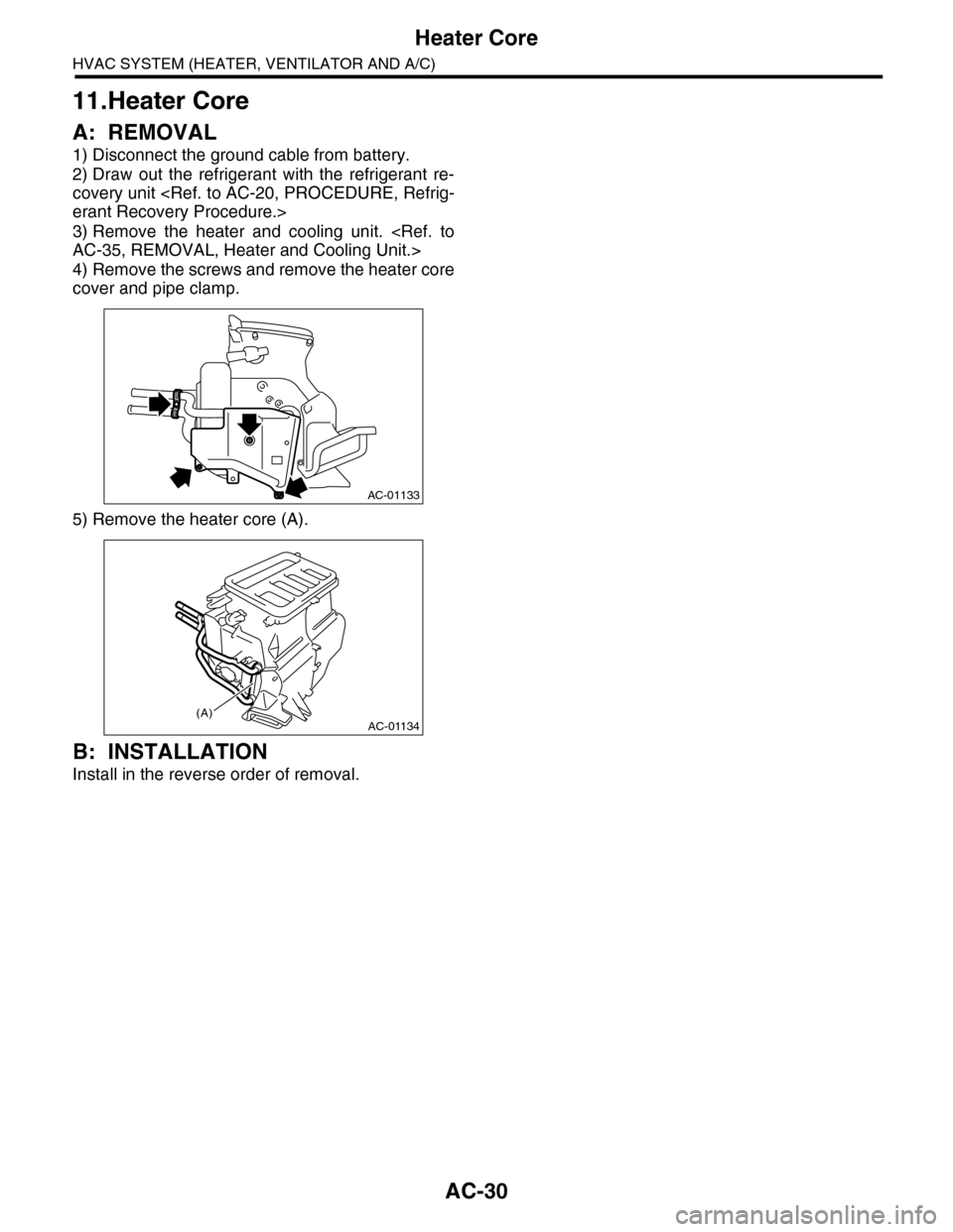
4) Remove the screws and remove the heater core
cover and pipe clamp.
5) Remove the heater core (A).
B: INSTALLATION
Install in the reverse order of removal.
AC-01133
AC-01134(A)
Page 361 of 2453
AC-35
Heater and Cooling Unit
HVAC SYSTEM (HEATER, VENTILATOR AND A/C)
16.Heater and Cooling Unit
A: REMOVAL
1. FRONT
1) Disconnect the ground cable from battery.
2) Using the refrigerant recovery system, dis-
charge refrigerant.
3) Drain engine coolant from the radiator.
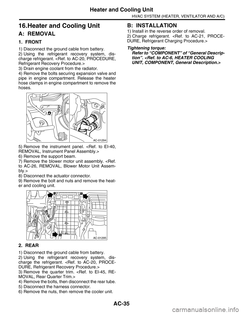
4) Remove the bolts securing expansion valve and
pipe in engine compartment. Release the heater
hose clamps in engine compartment to remove the
hoses.
5) Remove the instrument panel.
6) Remove the support beam.
7) Remove the blower motor unit assembly.
bly.>
8) Disconnect the actuator connector.
9) Remove the bolt and nuts and remove the heat-
er and cooling unit.
2. REAR
1) Disconnect the ground cable from battery.
2) Using the refrigerant recovery system, dis-
charge the refrigerant.
3) Remove the quarter trim.
4) Remove the bolts, then disconnect the rear tube.
5) Disconnect the harness connector.
6) Remove the nuts, then remove the cooler unit.
B: INSTALLATION
1) Install in the reverse order of removal.
2) Charge refrigerant.
Tightening torque:
Refer to “COMPONENT” of “General Descrip-
tion”.
AC-01294
AC-01295
Page 544 of 2453
LI-11
Headlight Assembly
LIGHTING SYSTEM
10.Headlight Assembly
A: REMOVAL
1) Disconnect the ground cable from battery.
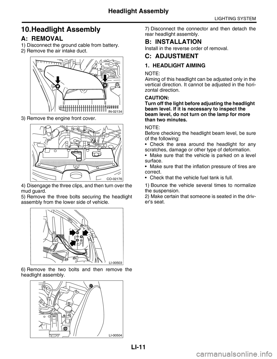
2) Remove the air intake duct.
3) Remove the engine front cover.
4) Disengage the three clips, and then turn over the
mud guard.
5) Remove the three bolts securing the headlight
assembly from the lower side of vehicle.
6) Remove the two bolts and then remove the
headlight assembly.
7) Disconnect the connector and then detach the
rear headlight assembly.
B: INSTALLATION
Install in the reverse order of removal.
C: ADJUSTMENT
1. HEADLIGHT AIMING
NOTE:
Aiming of this headlight can be adjusted only in the
vertical direction. It cannot be adjusted in the hori-
zontal direction.
CAUTION:
Turn off the light before adjusting the headlight
beam level. If it is necessary to inspect the
beam level, do not turn on the lamp for more
than two minutes.
NOTE:
Before checking the headlight beam level, be sure
of the following:
•Check the area around the headlight for any
scratches, damage or other type of deformation.
•Make sure that the vehicle is parked on a level
surface.
•Make sure that the inflation pressure of tires are
correct.
•Check that the vehicle fuel tank is full.
1) Bounce the vehicle several times to normalize
the suspension.
2) Make certain that someone is seated in the driv-
er's seat.
IN-02134
CO-02176
LI-00503
LI-00504
Page 559 of 2453
LI-26
License Plate Light Assembly
LIGHTING SYSTEM
24.License Plate Light Assembly
A: REMOVAL
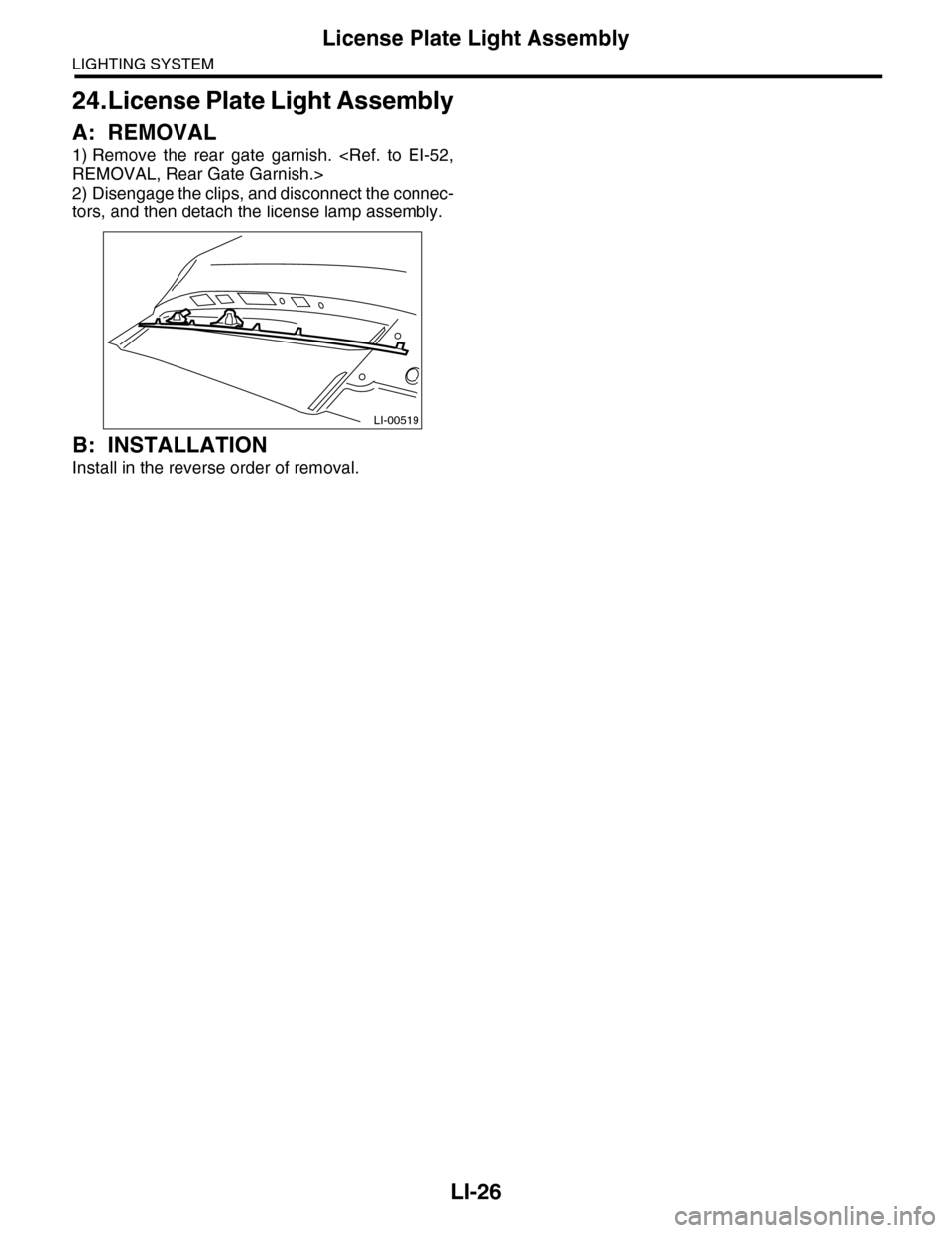
1) Remove the rear gate garnish.
2) Disengage the clips, and disconnect the connec-
tors, and then detach the license lamp assembly.
B: INSTALLATION
Install in the reverse order of removal.
LI-00519
Page 664 of 2453
SL-35
Front Outer Handle
SECURITY AND LOCKS
6. Front Outer Handle
A: REMOVAL
1) Raise the front door glass to the top position.
2) Remove the door trim.
3) Remove the sealing cover.
4) Remove the plug at the rear end of the door pan-
el.
5) Remove the rod clamp.
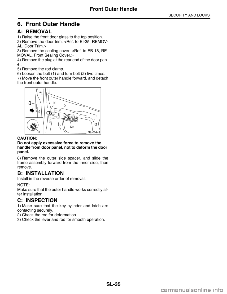
6) Loosen the bolt (1) and turn bolt (2) five times.
7) Move the front outer handle forward, and detach
the front outer handle.
CAUTION:
Do not apply excessive force to remove the
handle from door panel, not to deform the door
panel.
8) Remove the outer side spacer, and slide the
frame assembly forward from the inner side, then
remove.
B: INSTALLATION
Install in the reverse order of removal.
NOTE:
Make sure that the outer handle works correctly af-
ter installation.
C: INSPECTION
1) Make sure that the key cylinder and latch are
contacting securely.
2) Check the rod for deformation.
3) Check the lever and rod for smooth operation.
SL-00442
(1)
(1)
(2)
Page 669 of 2453
SL-40
Rear Door Latch and Door Lock Actuator Assembly
SECURITY AND LOCKS
11.Rear Door Latch and Door
Lock Actuator Assembly
A: REMOVAL
1) Raise the door glass to the top position.
2) Disconnect the ground cable from battery.
3) Remove the rear door trim.
4) Remove the cable from rear inner remote.
5) Remove the sealing cover.
6) Remove the rear sash.
7) Pull out the cable from the cable clamp of the
outer handle.
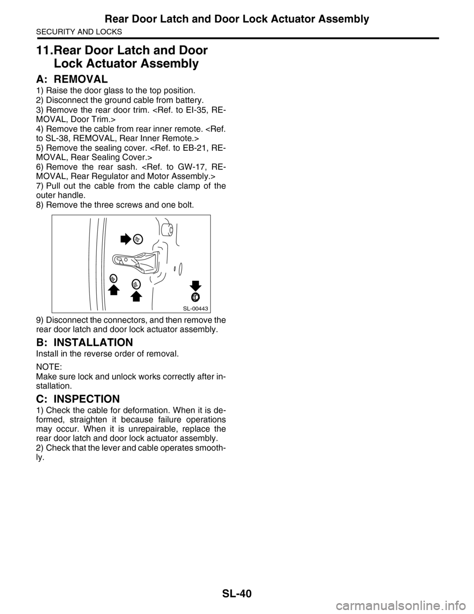
8) Remove the three screws and one bolt.
9) Disconnect the connectors, and then remove the
rear door latch and door lock actuator assembly.
B: INSTALLATION
Install in the reverse order of removal.
NOTE:
Make sure lock and unlock works correctly after in-
stallation.
C: INSPECTION
1) Check the cable for deformation. When it is de-
formed, straighten it because failure operations
may occur. When it is unrepairable, replace the
rear door latch and door lock actuator assembly.
2) Check that the lever and cable operates smooth-
ly.
SL-00443
Page 862 of 2453
FS-14
Front Stabilizer
FRONT SUSPENSION
4. Front Stabilizer
A: REMOVAL
1) Lift-up the vehicle, and then remove the front
wheels.
2) Remove the front under cover.
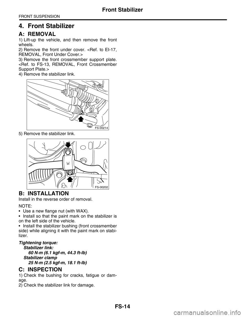
3) Remove the front crossmember support plate.
4) Remove the stabilizer link.
5) Remove the stabilizer link.
B: INSTALLATION
Install in the reverse order of removal.
NOTE:
•Use a new flange nut (with WAX).
•Install so that the paint mark on the stabilizer is
on the left side of the vehicle.
•Install the stabilizer bushing (front crossmember
side) while aligning it with the paint mark on stabi-
lizer.
Tightening torque:
Stabilizer link:
60 N·m (6.1 kgf-m, 44.3 ft-lb)
Stabilizer clamp
25 N·m (2.5 kgf-m, 18.1 ft-lb)
C: INSPECTION
1) Check the bushing for cracks, fatigue or dam-
age.
2) Check the stabilizer link for damage.
FS-00214
FS-00202
Page 871 of 2453
FS-23
Front Crossmember
FRONT SUSPENSION
8. Front Crossmember
A: REMOVAL
1) Lift-up the vehicle, and then remove the front
wheels.
2) Remove the front exhaust pipe.
3) Remove the front crossmember support plate.
4) Remove the front stabilizer.
5) Disconnect the tie-rod end from housing.
6) Remove the front arm.
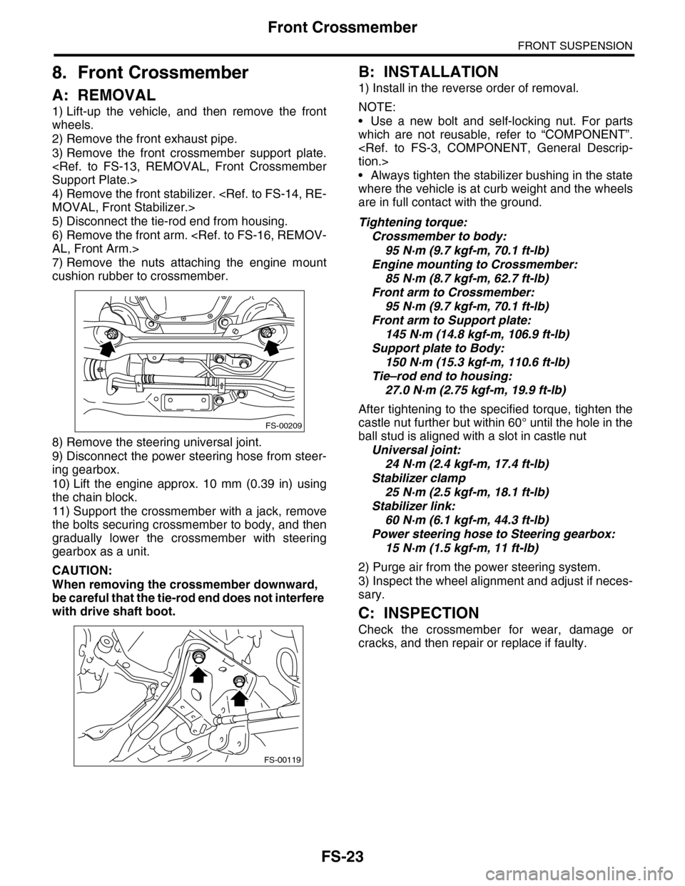
7) Remove the nuts attaching the engine mount
cushion rubber to crossmember.
8) Remove the steering universal joint.
9) Disconnect the power steering hose from steer-
ing gearbox.
10) Lift the engine approx. 10 mm (0.39 in) using
the chain block.
11) Support the crossmember with a jack, remove
the bolts securing crossmember to body, and then
gradually lower the crossmember with steering
gearbox as a unit.
CAUTION:
When removing the crossmember downward,
be careful that the tie-rod end does not interfere
with drive shaft boot.
B: INSTALLATION
1) Install in the reverse order of removal.
NOTE:
•Use a new bolt and self-locking nut. For parts
which are not reusable, refer to “COMPONENT”.
•Always tighten the stabilizer bushing in the state
where the vehicle is at curb weight and the wheels
are in full contact with the ground.
Tightening torque:
Crossmember to body:
95 N·m (9.7 kgf-m, 70.1 ft-lb)
Engine mounting to Crossmember:
85 N·m (8.7 kgf-m, 62.7 ft-lb)
Front arm to Crossmember:
95 N·m (9.7 kgf-m, 70.1 ft-lb)
Front arm to Support plate:
145 N·m (14.8 kgf-m, 106.9 ft-lb)
Support plate to Body:
150 N·m (15.3 kgf-m, 110.6 ft-lb)
Tie–rod end to housing:
27.0 N·m (2.75 kgf-m, 19.9 ft-lb)
After tightening to the specified torque, tighten the
castle nut further but within 60° until the hole in the
ball stud is aligned with a slot in castle nut
Universal joint:
24 N·m (2.4 kgf-m, 17.4 ft-lb)
Stabilizer clamp
25 N·m (2.5 kgf-m, 18.1 ft-lb)
Stabilizer link:
60 N·m (6.1 kgf-m, 44.3 ft-lb)
Power steering hose to Steering gearbox:
15 N·m (1.5 kgf-m, 11 ft-lb)
2) Purge air from the power steering system.
3) Inspect the wheel alignment and adjust if neces-
sary.
C: INSPECTION
Check the crossmember for wear, damage or
cracks, and then repair or replace if faulty.
FS-00209
FS-00119
Page 877 of 2453
PB-6
Parking Brake Cable
PARKING BRAKE
5) Lift-up the vehicle, and then remove the rear
wheels.
6) Remove the rear parking brake cable from the
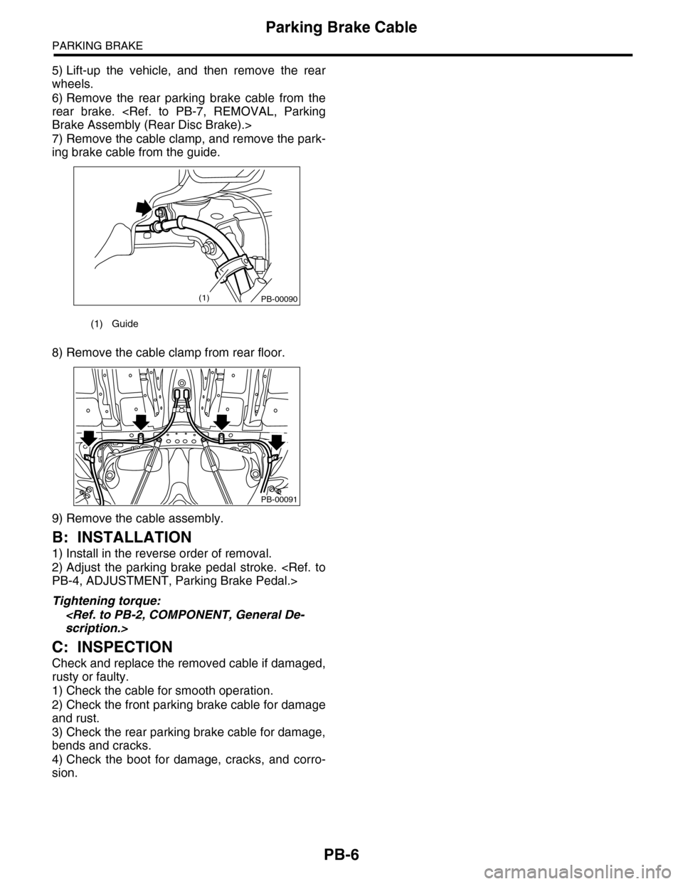
rear brake.
7) Remove the cable clamp, and remove the park-
ing brake cable from the guide.
8) Remove the cable clamp from rear floor.
9) Remove the cable assembly.
B: INSTALLATION
1) Install in the reverse order of removal.
2) Adjust the parking brake pedal stroke.
Tightening torque:
C: INSPECTION
Check and replace the removed cable if damaged,
rusty or faulty.
1) Check the cable for smooth operation.
2) Check the front parking brake cable for damage
and rust.
3) Check the rear parking brake cable for damage,
bends and cracks.
4) Check the boot for damage, cracks, and corro-
sion.
(1) Guide
PB-00090(1)
PB-00091