center console SUBARU TRIBECA 2009 1.G Service Workshop Manual
[x] Cancel search | Manufacturer: SUBARU, Model Year: 2009, Model line: TRIBECA, Model: SUBARU TRIBECA 2009 1.GPages: 2453, PDF Size: 46.32 MB
Page 20 of 2453
AB-21
Airbag Control Module
AIRBAG SYSTEM
8. Airbag Control Module
A: REMOVAL
CAUTION:
•Do not disassemble the airbag control mod-
ule.
•If the airbag control module is deformed or if
the fault occurs by water, replace the airbag
control module with a new one.
•Do not drop the airbag control module.
•After removal, keep the airbag control mod-
ule on a dry, clean surface away from moisture,
heat and dust.
1) Turn the ignition switch to OFF.
2) Disconnect the ground cable from battery and
wait for at least 20 seconds before starting work.
3) Remove the center console.
4) Remove the console box.
5) Remove the instrument panel lower cover.
er.>
6) Remove the glove box.
7) Remove the audio unit.
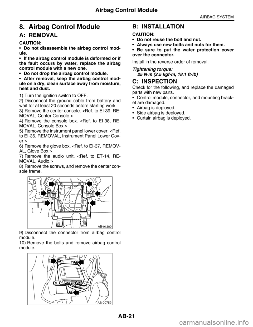
8) Remove the screws, and remove the center con-
sole frame.
9) Disconnect the connector from airbag control
module.
10) Remove the bolts and remove airbag control
module.
B: INSTALLATION
CAUTION:
•Do not reuse the bolt and nut.
•Always use new bolts and nuts for them.
•Be sure to put the water protection cover
over the connector.
Install in the reverse order of removal.
Tightening torque:
25 N·m (2.5 kgf-m, 18.1 ft-lb)
C: INSPECTION
Check for the following, and replace the damaged
parts with new parts.
•Control module, connector, and mounting brack-
et are damaged.
•Airbag is deployed.
•Side airbag is deployed.
•Curtain airbag is deployed.
AB-01280
AB-00759
Page 200 of 2453
ET-14
Audio
ENTERTAINMENT
9. Audio
A: REMOVAL
1) Disconnect the ground cable from battery.
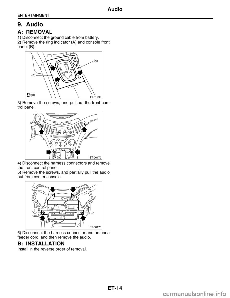
2) Remove the ring indicator (A) and console front
panel (B).
3) Remove the screws, and pull out the front con-
trol panel.
4) Disconnect the harness connectors and remove
the front control panel.
5) Remove the screws, and partially pull the audio
out from center console.
6) Disconnect the harness connector and antenna
feeder cord, and then remove the audio.
B: INSTALLATION
Install in the reverse order of removal.
EI-01299
PRND
:(B)
(B)
(A)
ET-00172
ET-00173
Page 215 of 2453
ET-30
Front Accessory Power Supply Socket
ENTERTAINMENT
25.Front Accessory Power Sup-
ply Socket
A: REMOVAL
1) Disconnect the ground cable from battery.
2) Remove the console box.
3) Disconnect the harness connector, and remove
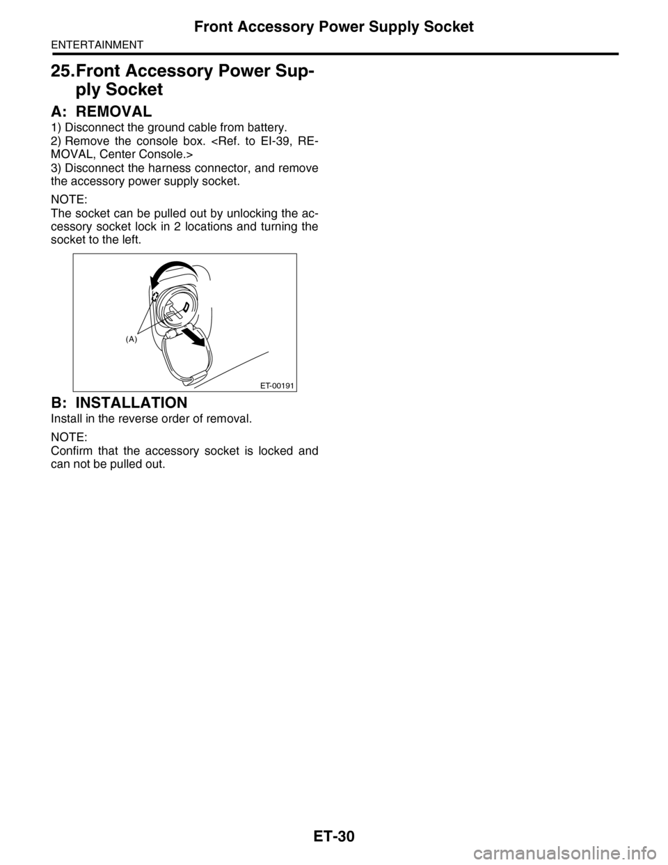
the accessory power supply socket.
NOTE:
The socket can be pulled out by unlocking the ac-
cessory socket lock in 2 locations and turning the
socket to the left.
B: INSTALLATION
Install in the reverse order of removal.
NOTE:
Confirm that the accessory socket is locked and
can not be pulled out.
ET-00191
(A)
Page 216 of 2453
ET-31
Rear Accessory Power Supply Socket
ENTERTAINMENT
26.Rear Accessory Power Sup-
ply Socket
A: REMOVAL
1) Disconnect the ground cable from battery.
2) Remove the console box.
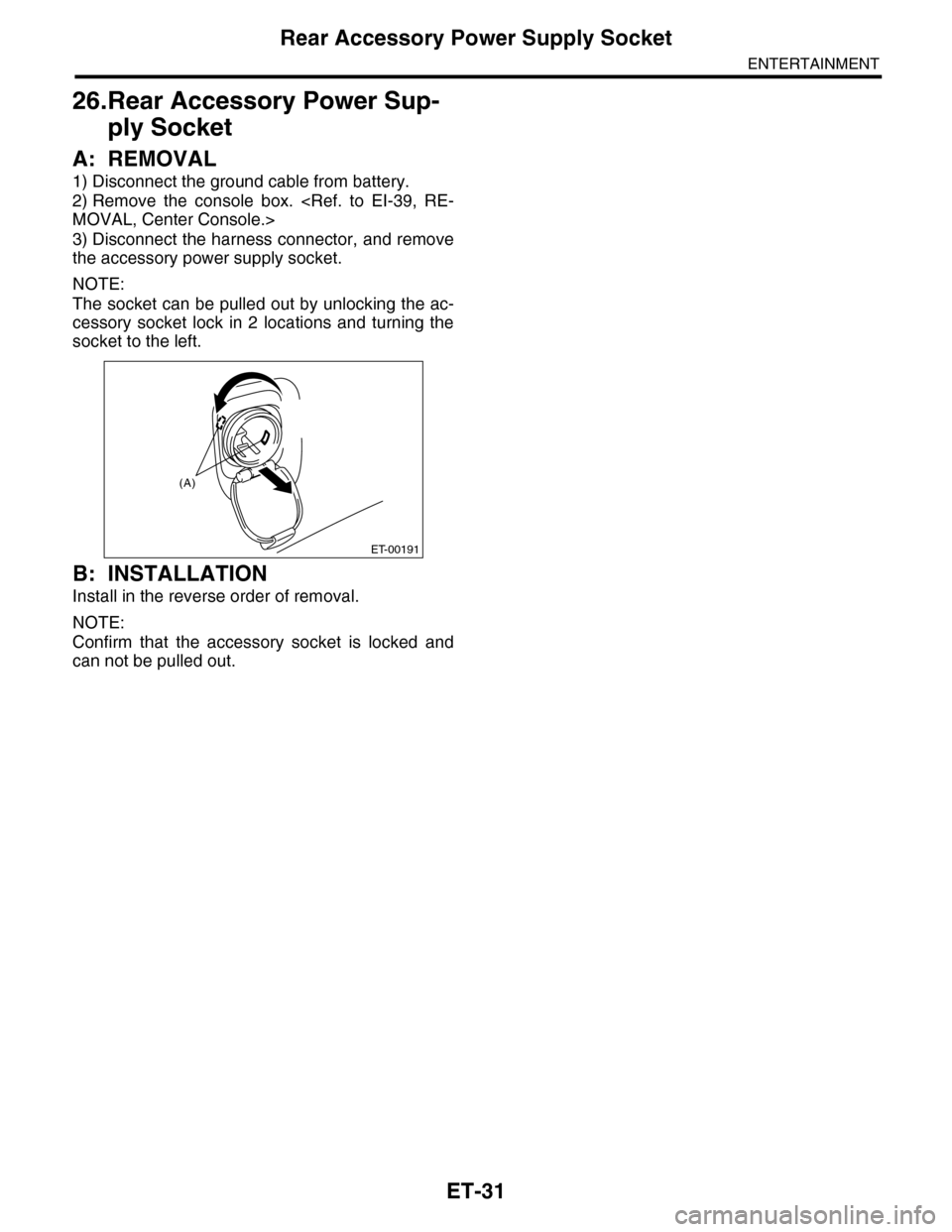
3) Disconnect the harness connector, and remove
the accessory power supply socket.
NOTE:
The socket can be pulled out by unlocking the ac-
cessory socket lock in 2 locations and turning the
socket to the left.
B: INSTALLATION
Install in the reverse order of removal.
NOTE:
Confirm that the accessory socket is locked and
can not be pulled out.
ET-00191
(A)
Page 254 of 2453
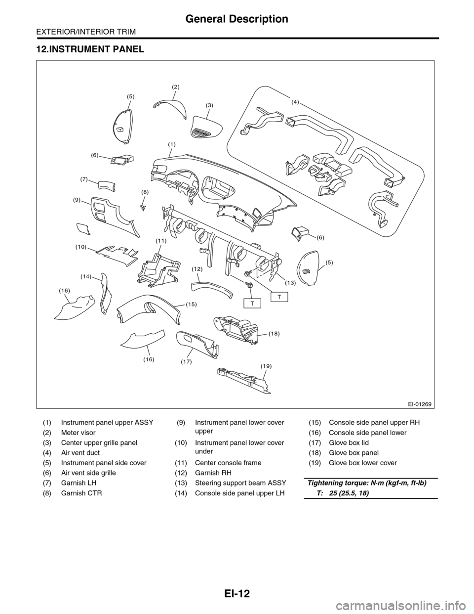
EI-12
General Description
EXTERIOR/INTERIOR TRIM
12.INSTRUMENT PANEL
(1) Instrument panel upper ASSY (9)
Instrument panel lower cover
upper
(15) Console side panel upper RH
(2) Meter visor (16) Console side panel lower
(3) Center upper grille panel (10)
Instrument panel lower cover
under
(17) Glove box lid
(4) Air vent duct (18) Glove box panel
(5) Instrument panel side cover (11) Center console frame (19) Glove box lower cover
(6) Air vent side grille (12) Garnish RH
(7) Garnish LH (13) Steering support beam ASSYTightening torque: N·m (kgf-m, ft-lb)
(8) Garnish CTR (14) Console side panel upper LHT: 25 (25.5, 18)
EI-01269
TT
(2)
(5)
(1)
(8)
(6)
(19)
(11)
(12)
(15)
(17)
(5)
(6)
(3)(4)
(7)
(9)
(10)
(14)
(16)
(18)
(13)
(16)
Page 281 of 2453
EI-39
Center Console
EXTERIOR/INTERIOR TRIM
16.Center Console
A: REMOVAL
1) Remove the control panel.
2) Remove the instrument panel lower cover.
er.>
3) Remove the glove box.
4) Remove the console box.
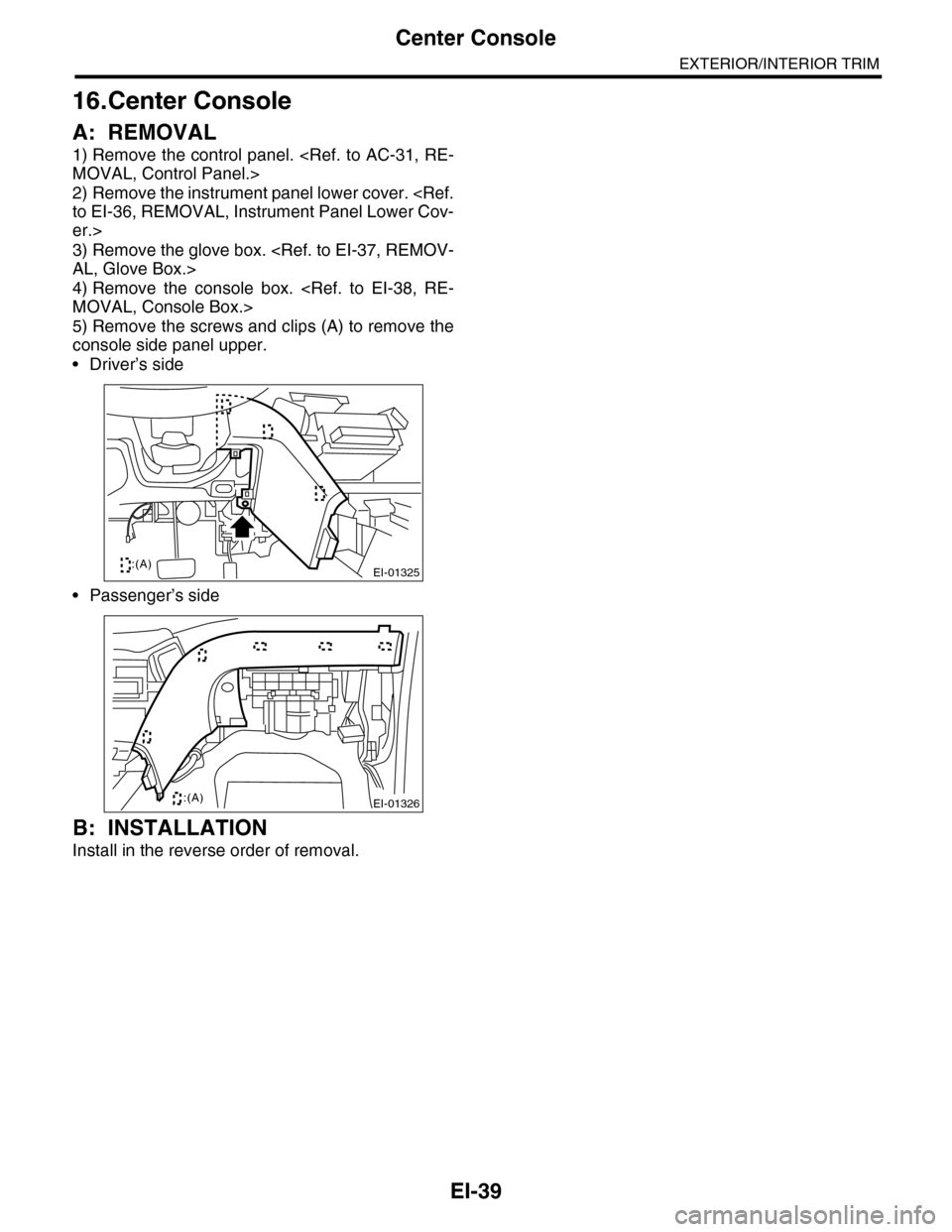
5) Remove the screws and clips (A) to remove the
console side panel upper.
•Driver’s side
•Passenger’s side
B: INSTALLATION
Install in the reverse order of removal.
EI-01325:(A)
EI-01326:(A)
Page 282 of 2453
EI-40
Instrument Panel Assembly
EXTERIOR/INTERIOR TRIM
17.Instrument Panel Assembly
A: REMOVAL
CAUTION:
Take care of the following when removing the
instrument panel from the vehicle body.
•Refer to “CAUTION” of “General Description”
before starting the work.
•Be sure to disconnect each harness connec-
tor. Applying excessive pulling force may dam-
age the harness.
•Be careful to the harness of airbag system.
Damage of the harness may cause the air bag
system malfunction.
•Take care not to damage the interior trims
when removing the instrument panel from the
vehicle body.
NOTE:
•Putting alignment marks to each connector as
necessary facilitates the reassembly work.
•When storing the removed instrument panel, be
sure to prepare a table or the like to put the instru-
ment panel on in order to prevent damage.
1. INSTRUMENT PANEL UPPER
1) Disconnect the ground cable from battery and
wait for at least 20 seconds before starting work.
2) Remove the console box.
3) Remove the instrument panel lower cover.
er.>
4) Remove the glove box.
5) Remove the center console.
6) Remove the audio unit.
7) Remove the combination meter assembly.
8) Remove the upper grille.
9) Remove the multi function display or navigation
monitor, and warning box.
10) Remove the front pillar upper trim.
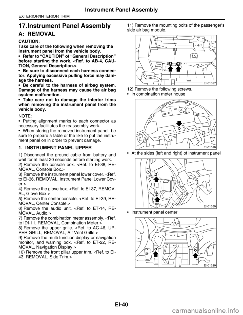
11) Remove the mounting bolts of the passenger’s
side air bag module.
12) Remove the following screws.
•In combination meter house
•At the sides (left and right) of instrument panel
•Instrument panel center
EI-01327
EI-01328
EI-01330
EI-01329
Page 283 of 2453
EI-41
Instrument Panel Assembly
EXTERIOR/INTERIOR TRIM
13) Make sure that the instrument panel upper is
removed from the steering support beam
14) Disconnect the connectors, and remove the in-
strument panel from vehicle body.
15) Remove the heater vent duct.
16) Remove the air vent grille.
17) Remove the passenger airbag module.
ule.>
2. STEERING SUPPORT BEAM
1) Remove the instrument panel upper.
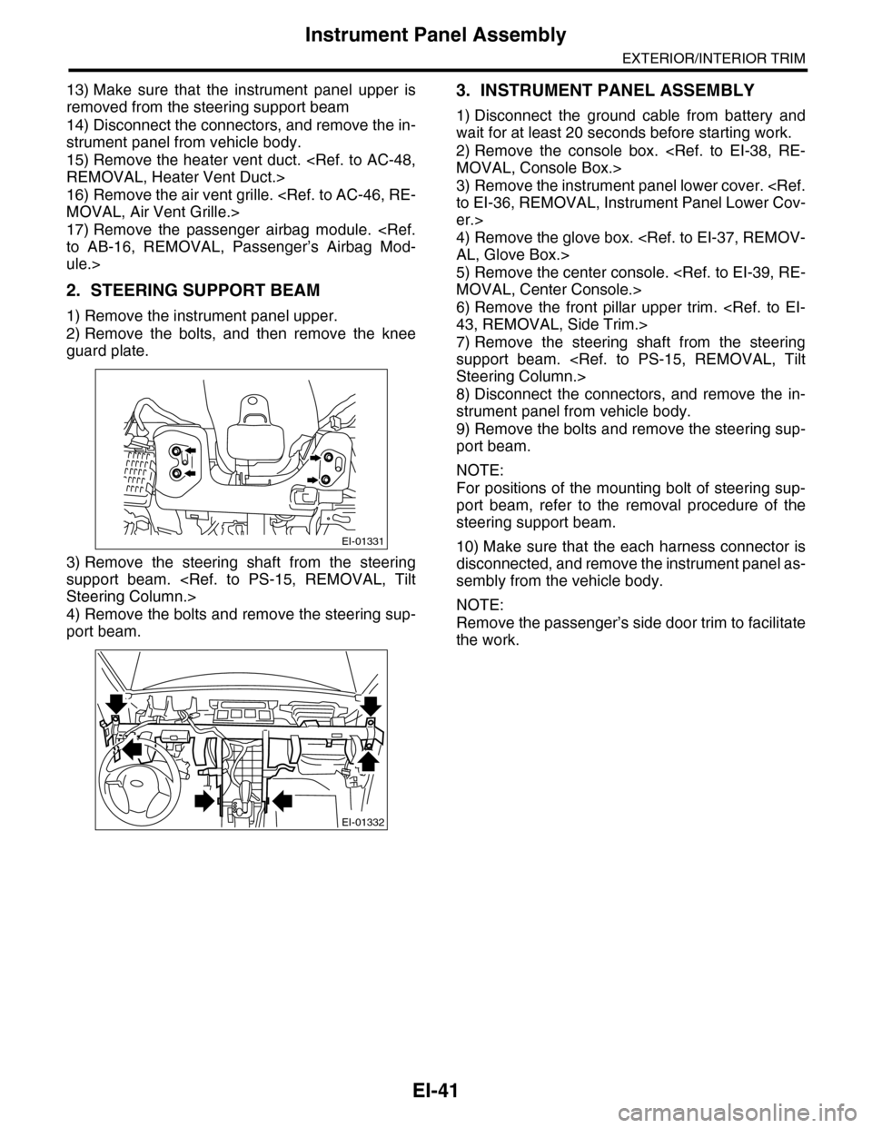
2) Remove the bolts, and then remove the knee
guard plate.
3) Remove the steering shaft from the steering
support beam.
4) Remove the bolts and remove the steering sup-
port beam.
3. INSTRUMENT PANEL ASSEMBLY
1) Disconnect the ground cable from battery and
wait for at least 20 seconds before starting work.
2) Remove the console box.
3) Remove the instrument panel lower cover.
er.>
4) Remove the glove box.
5) Remove the center console.
6) Remove the front pillar upper trim.
7) Remove the steering shaft from the steering
support beam.
8) Disconnect the connectors, and remove the in-
strument panel from vehicle body.
9) Remove the bolts and remove the steering sup-
port beam.
NOTE:
For positions of the mounting bolt of steering sup-
port beam, refer to the removal procedure of the
steering support beam.
10) Make sure that the each harness connector is
disconnected, and remove the instrument panel as-
sembly from the vehicle body.
NOTE:
Remove the passenger’s side door trim to facilitate
the work.
EI-01331
EI-01332
Page 289 of 2453
EI-47
Floor Mat
EXTERIOR/INTERIOR TRIM
20.Floor Mat
A: REMOVAL
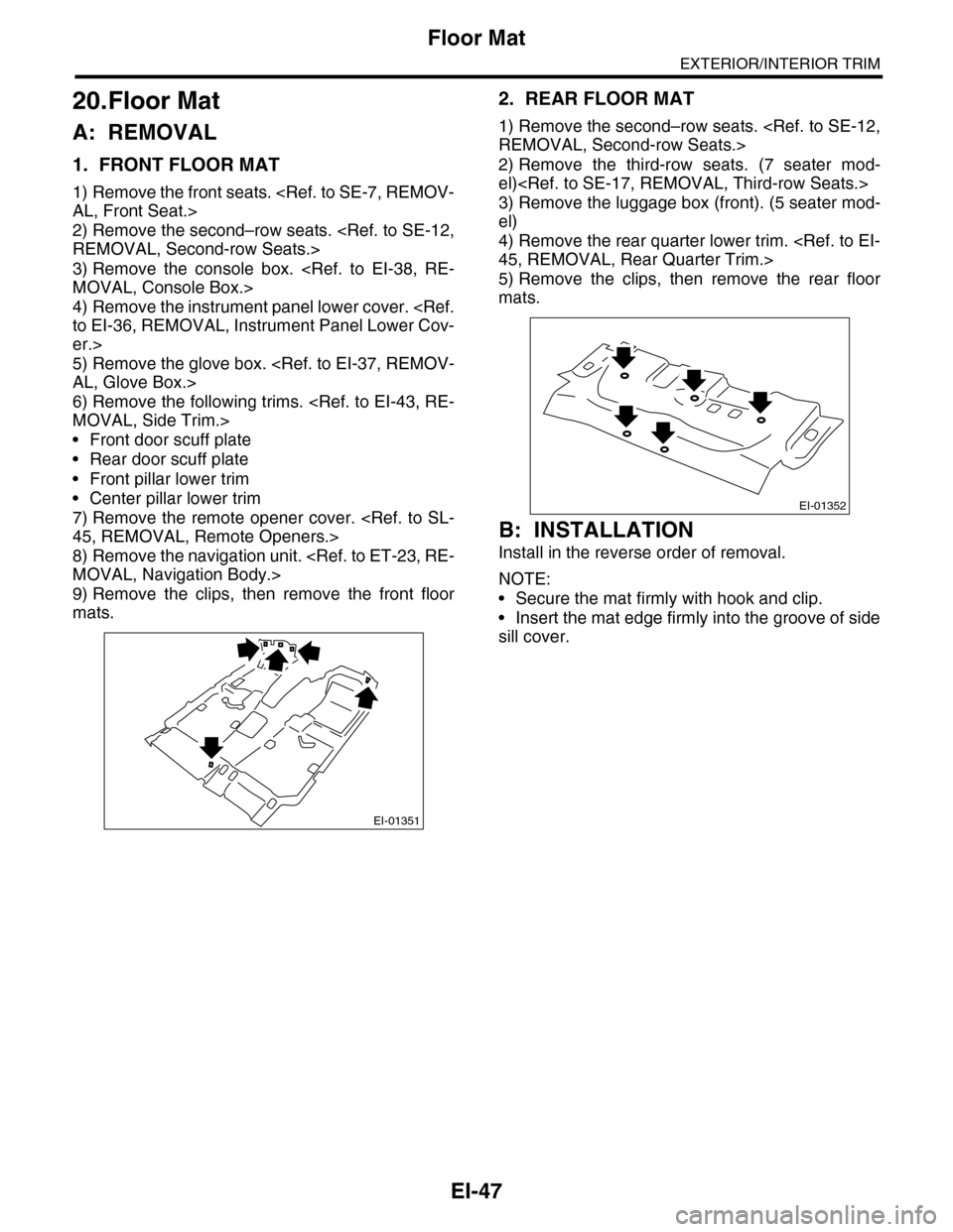
1. FRONT FLOOR MAT
1) Remove the front seats.
2) Remove the second–row seats.
3) Remove the console box.
4) Remove the instrument panel lower cover.
er.>
5) Remove the glove box.
6) Remove the following trims.
•Front door scuff plate
•Rear door scuff plate
•Front pillar lower trim
•Center pillar lower trim
7) Remove the remote opener cover.
8) Remove the navigation unit.
9) Remove the clips, then remove the front floor
mats.
2. REAR FLOOR MAT
1) Remove the second–row seats.
2) Remove the third-row seats. (7 seater mod-
el)
3) Remove the luggage box (front). (5 seater mod-
el)
4) Remove the rear quarter lower trim.
5) Remove the clips, then remove the rear floor
mats.
B: INSTALLATION
Install in the reverse order of removal.
NOTE:
•Secure the mat firmly with hook and clip.
•Insert the mat edge firmly into the groove of side
sill cover.
EI-01351
EI-01352
Page 380 of 2453
AC(diag)-3
General Description
HVAC SYSTEM (AUTO A/C) (DIAGNOSTICS)
2. General Description
A: CAUTION
1) Never connect the battery in reverse polarity.
•Auto A/C control module may be destroyed in-
stantly.
2) Do not disconnect the battery terminals while the
engine is running.
•A large counter electromotive force will be gener-
ated in the generator, and this voltage may damage
electronic parts such as auto A/C control module
etc.
3) Before disconnecting the connectors of each
sensor and the auto A/C control module, be sure to
turn the ignition switch to OFF.
•Auto A/C control module may be damaged.
4) Every A/C-related part is a precision part. Do not
drop them.
5) Airbag system wiring harness is routed near the
A/C control panel and junction box.
CAUTION:
•For airbag system, yellow-colored wiring har-
ness and connectors are all used. Do not use
the electrical test equipment on these circuits.
•Be careful not to damage the airbag system
wiring harness when servicing the A/C control
panel and junction box.
B: INSPECTION
Before performing the diagnosis, check the follow-
ing items which might affect A/C system problems.
1. BATTERY
1) Measure the battery voltage and specific gravity
of electrolyte.
Standard voltage: 12 V
Specific gravity: 1.260 or more
2) Check the condition of the fuses for A/C system
power supply and other fuses.
3) Check the condition of harness and harness
connector connections.
2. ASPIRATOR HOSE
1) Turn the ignition switch to ON, and press the A/
C switch.
2) Turn the temperature control dial to maximum
hot position.
3) Turn the air flow control dial to “DEF” position.
4) Turn the fan speed control dial to 4th position.
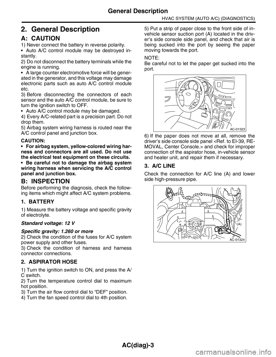
5) Put a strip of paper close to the front side of in-
vehicle sensor suction port (A) located in the driv-
er’s side console side panel, and check that air is
being sucked into the port by seeing the paper
moving towards the port.
NOTE:
Be careful not to let the paper get sucked into the
port.
6) If the paper does not move at all, remove the
driver’s side console side panel
connection of the aspirator hose, in-vehicle sensor
and heater unit, and repair them if necessary.
3. A/C LINE
Check the connection for A/C line (A) and lower
side high-pressure pipe.
AC-01323
AC-01324
(A)