oil pressure SUBARU TRIBECA 2009 1.G Service Workshop Manual
[x] Cancel search | Manufacturer: SUBARU, Model Year: 2009, Model line: TRIBECA, Model: SUBARU TRIBECA 2009 1.GPages: 2453, PDF Size: 46.32 MB
Page 243 of 2453
EB-24
Rear Gate
EXTERIOR BODY PANELS
C: DISPOSAL
1. REAR GATE DAMPER STAY
CAUTION:
Gas is colorless, odorless, and harmless. How-
ever, gas pressure may spray cutting powder or
oil. Be sure to wear dust-resistant goggles.
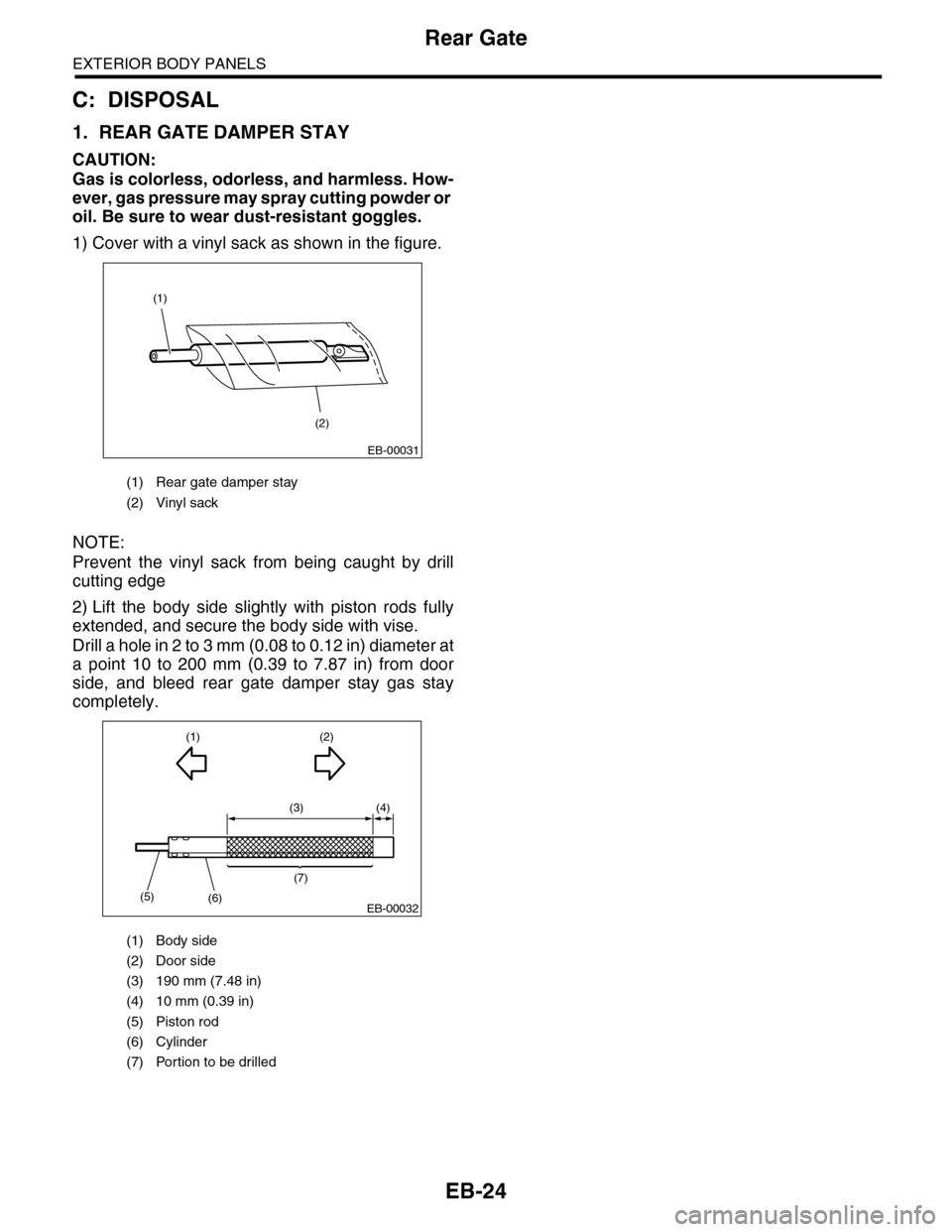
1) Cover with a vinyl sack as shown in the figure.
NOTE:
Prevent the vinyl sack from being caught by drill
cutting edge
2) Lift the body side slightly with piston rods fully
extended, and secure the body side with vise.
Drill a hole in 2 to 3 mm (0.08 to 0.12 in) diameter at
a point 10 to 200 mm (0.39 to 7.87 in) from door
side, and bleed rear gate damper stay gas stay
completely.
(1) Rear gate damper stay
(2) Vinyl sack
(1) Body side
(2) Door side
(3) 190 mm (7.48 in)
(4) 10 mm (0.39 in)
(5) Piston rod
(6) Cylinder
(7) Portion to be drilled
(1)
(2)
EB-00031
(3) (4)
(1)
(5)(6)
(7)
(2)
EB-00032
Page 265 of 2453
EI-23
Front Bumper
EXTERIOR/INTERIOR TRIM
C: REPAIR
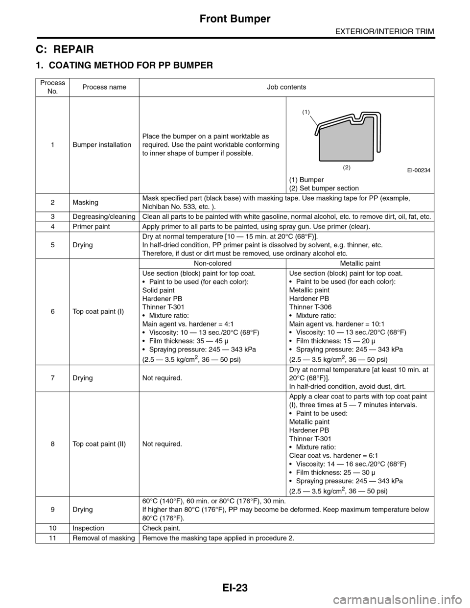
1. COATING METHOD FOR PP BUMPER
Process
No.Process name Job contents
1Bumper installation
Place the bumper on a paint worktable as
required. Use the paint worktable conforming
to inner shape of bumper if possible.
(1) Bumper
(2) Set bumper section
2MaskingMask specified part (black base) with masking tape. Use masking tape for PP (example,
Nichiban No. 533, etc. ).
3Degreasing/cleaningClean all parts to be painted with white gasoline, normal alcohol, etc. to remove dirt, oil, fat, etc.
4Primer paint Apply primer to all parts to be painted, using spray gun. Use primer (clear).
5Drying
Dry at normal temperature [10 — 15 min. at 20°C (68°F)].
In half-dried condition, PP primer paint is dissolved by solvent, e.g. thinner, etc.
Therefore, if dust or dirt must be removed, use ordinary alcohol etc.
6Top coat paint (I)
Non-colored Metallic paint
Use section (block) paint for top coat.
•Paint to be used (for each color):
Solid paint
Hardener PB
Thinner T-301
•Mixture ratio:
Main agent vs. hardener = 4:1
• Viscosity: 10 — 13 sec./20°C (68°F)
•Film thickness: 35 — 45 µ
•Spraying pressure: 245 — 343 kPa
(2.5 — 3.5 kg/cm2, 36 — 50 psi)
Use section (block) paint for top coat.
•Paint to be used (for each color):
Metallic paint
Hardener PB
Thinner T-306
•Mixture ratio:
Main agent vs. hardener = 10:1
•Viscosity: 10 — 13 sec./20°C (68°F)
•Film thickness: 15 — 20 µ
•Spraying pressure: 245 — 343 kPa
(2.5 — 3.5 kg/cm2, 36 — 50 psi)
7Drying Not required.
Dry at normal temperature [at least 10 min. at
20°C (68°F)].
In half-dried condition, avoid dust, dirt.
8Top coat paint (II)Not required.
Apply a clear coat to parts with top coat paint
(I), three times at 5 — 7 minutes intervals.
•Paint to be used:
Metallic paint
Hardener PB
Thinner T-301
•Mixture ratio:
Clear coat vs. hardener = 6:1
•Viscosity: 14 — 16 sec./20°C (68°F)
•Film thickness: 25 — 30 µ
•Spraying pressure: 245 — 343 kPa
(2.5 — 3.5 kg/cm2, 36 — 50 psi)
9Drying
60°C (140°F), 60 min. or 80°C (176°F), 30 min.
If higher than 80°C (176°F), PP may become be deformed. Keep maximum temperature below
80°C (176°F).
10 Inspection Check paint.
11 Removal of masking Remove the masking tape applied in procedure 2.
EI-00234(2)
(1)
Page 340 of 2453
AC-14
General Description
HVAC SYSTEM (HEATER, VENTILATOR AND A/C)
C: CAUTION
1. HFC-134A A/C SYSTEM
•The cooling system components for the HFC-
134a system such as the refrigerant and compres-
sor oil are different from the conventional CFC-12
system components and they are incompatible with
each other.
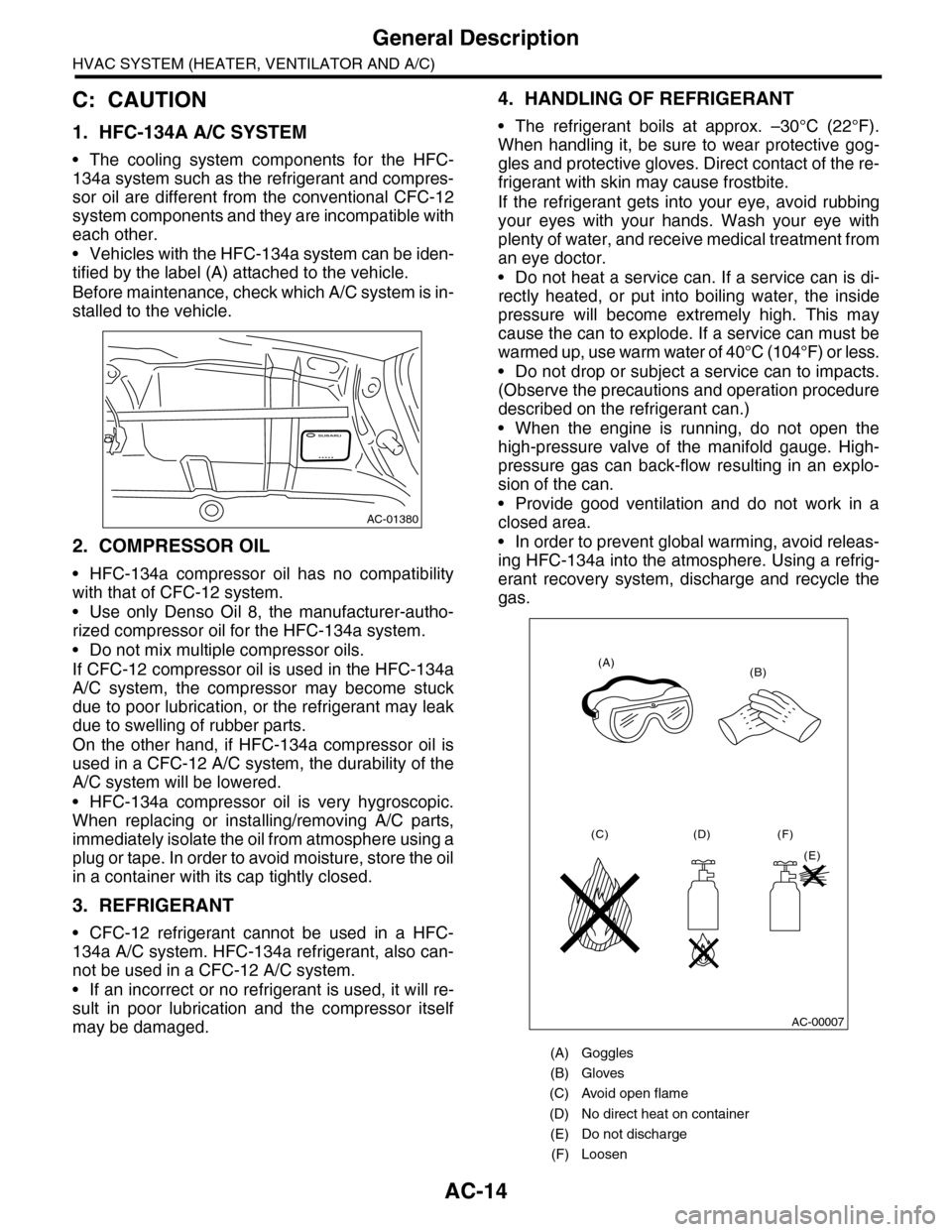
•Vehicles with the HFC-134a system can be iden-
tified by the label (A) attached to the vehicle.
Before maintenance, check which A/C system is in-
stalled to the vehicle.
2. COMPRESSOR OIL
•HFC-134a compressor oil has no compatibility
with that of CFC-12 system.
•Use only Denso Oil 8, the manufacturer-autho-
rized compressor oil for the HFC-134a system.
•Do not mix multiple compressor oils.
If CFC-12 compressor oil is used in the HFC-134a
A/C system, the compressor may become stuck
due to poor lubrication, or the refrigerant may leak
due to swelling of rubber parts.
On the other hand, if HFC-134a compressor oil is
used in a CFC-12 A/C system, the durability of the
A/C system will be lowered.
•HFC-134a compressor oil is very hygroscopic.
When replacing or installing/removing A/C parts,
immediately isolate the oil from atmosphere using a
plug or tape. In order to avoid moisture, store the oil
in a container with its cap tightly closed.
3. REFRIGERANT
•CFC-12 refrigerant cannot be used in a HFC-
134a A/C system. HFC-134a refrigerant, also can-
not be used in a CFC-12 A/C system.
•If an incorrect or no refrigerant is used, it will re-
sult in poor lubrication and the compressor itself
may be damaged.
4. HANDLING OF REFRIGERANT
•The refrigerant boils at approx. –30°C (22°F).
When handling it, be sure to wear protective gog-
gles and protective gloves. Direct contact of the re-
frigerant with skin may cause frostbite.
If the refrigerant gets into your eye, avoid rubbing
your eyes with your hands. Wash your eye with
plenty of water, and receive medical treatment from
an eye doctor.
•Do not heat a service can. If a service can is di-
rectly heated, or put into boiling water, the inside
pressure will become extremely high. This may
cause the can to explode. If a service can must be
warmed up, use warm water of 40°C (104°F) or less.
•Do not drop or subject a service can to impacts.
(Observe the precautions and operation procedure
described on the refrigerant can.)
•When the engine is running, do not open the
high-pressure valve of the manifold gauge. High-
pressure gas can back-flow resulting in an explo-
sion of the can.
•Provide good ventilation and do not work in a
closed area.
•In order to prevent global warming, avoid releas-
ing HFC-134a into the atmosphere. Using a refrig-
erant recovery system, discharge and recycle the
gas.
AC-01380
(A) Goggles
(B) Gloves
(C) Avoid open flame
(D) No direct heat on container
(E) Do not discharge
(F) Loosen
(A)(B)
(C) (D)
(E)
(F)
AC-00007
Page 342 of 2453
AC-16
General Description
HVAC SYSTEM (HEATER, VENTILATOR AND A/C)
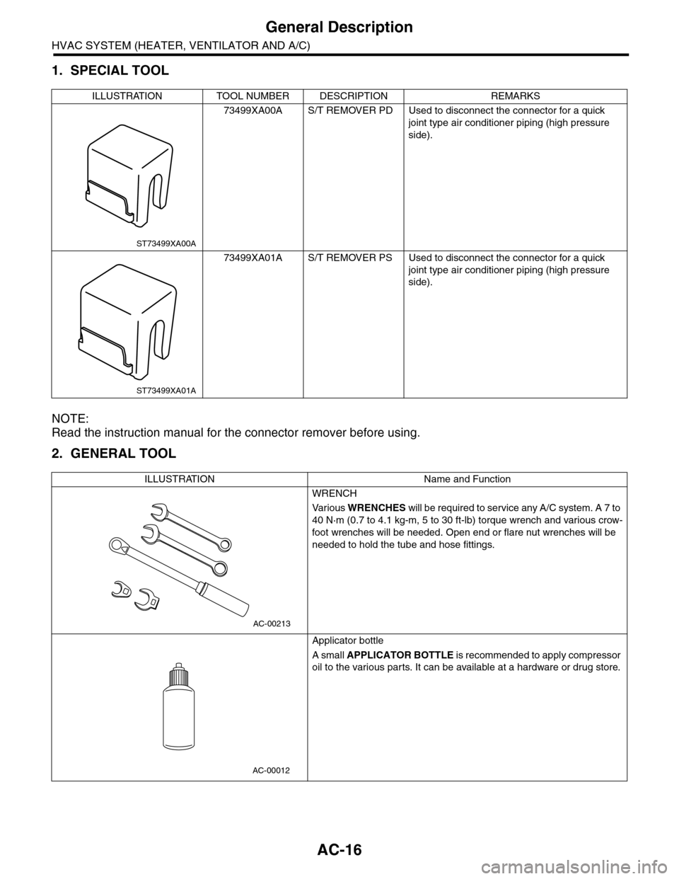
1. SPECIAL TOOL
NOTE:
Read the instruction manual for the connector remover before using.
2. GENERAL TOOL
ILLUSTRATION TOOL NUMBER DESCRIPTION REMARKS
73499XA00A S/T REMOVER PD Used to disconnect the connector for a quick
joint type air conditioner piping (high pressure
side).
73499XA01A S/T REMOVER PS Used to disconnect the connector for a quick
joint type air conditioner piping (high pressure
side).
ILLUSTRATION Name and Function
WRENCH
Va r i o u s WRENCHES will be required to service any A/C system. A 7 to
40 N·m (0.7 to 4.1 kg-m, 5 to 30 ft-lb) torque wrench and various crow-
foot wrenches will be needed. Open end or flare nut wrenches will be
needed to hold the tube and hose fittings.
Applicator bottle
A small APPLICATOR BOTTLE i s r e c om me nd e d to a p pl y co mp r e ss or
oil to the various parts. It can be available at a hardware or drug store.
ST73499XA00A
ST73499XA01A
AC-00213
AC-00012
Page 346 of 2453
AC-20
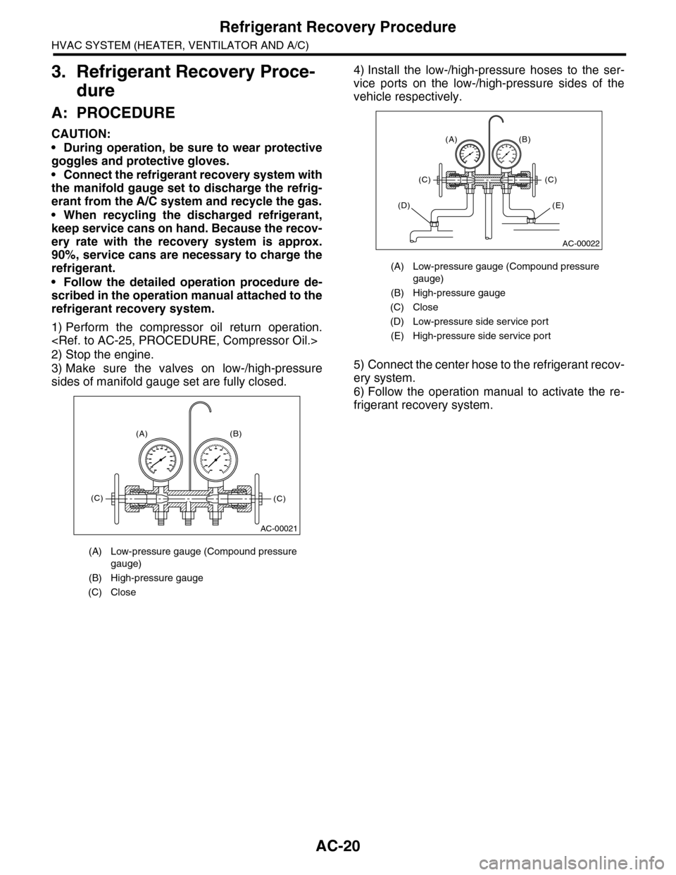
Refrigerant Recovery Procedure
HVAC SYSTEM (HEATER, VENTILATOR AND A/C)
3. Refrigerant Recovery Proce-
dure
A: PROCEDURE
CAUTION:
•During operation, be sure to wear protective
goggles and protective gloves.
•Connect the refrigerant recovery system with
the manifold gauge set to discharge the refrig-
erant from the A/C system and recycle the gas.
•When recycling the discharged refrigerant,
keep service cans on hand. Because the recov-
ery rate with the recovery system is approx.
90%, service cans are necessary to charge the
refrigerant.
•Follow the detailed operation procedure de-
scribed in the operation manual attached to the
refrigerant recovery system.
1) Perform the compressor oil return operation.
2) Stop the engine.
3) Make sure the valves on low-/high-pressure
sides of manifold gauge set are fully closed.
4) Install the low-/high-pressure hoses to the ser-
vice ports on the low-/high-pressure sides of the
vehicle respectively.
5) Connect the center hose to the refrigerant recov-
ery system.
6) Follow the operation manual to activate the re-
frigerant recovery system.
(A) Low-pressure gauge (Compound pressure
gauge)
(B) High-pressure gauge
(C) Close
AC-00021
(A) (B)
(C)(C)
(A) Low-pressure gauge (Compound pressure
gauge)
(B) High-pressure gauge
(C) Close
(D) Low-pressure side service port
(E) High-pressure side service port
AC-00022
(A) (B)
(C)(C)
(E)(D)
Page 347 of 2453
AC-21
Refrigerant Charging Procedure
HVAC SYSTEM (HEATER, VENTILATOR AND A/C)
4. Refrigerant Charging Proce-
dure
A: PROCEDURE
CAUTION:
•During operation, be sure to wear protective
goggles and protective gloves.
•Before charging the refrigerant, evacuate the
system to remove small amounts of moisture
remaining in the system.
The moisture in the system can be completely
evacuated only under the minimum vacuum
level. The minimum vacuum level affects the
temperature in the system.
•The list below shows the vacuum values nec-
essary to boil water at various temperatures. In
addition, the vacuum levels indicated on the
gauge are approx. 3.3 kPa (25 mmHg, 0.98 inHg)
lower than those measured at 304.8 m (1,000 ft)
above sea level.
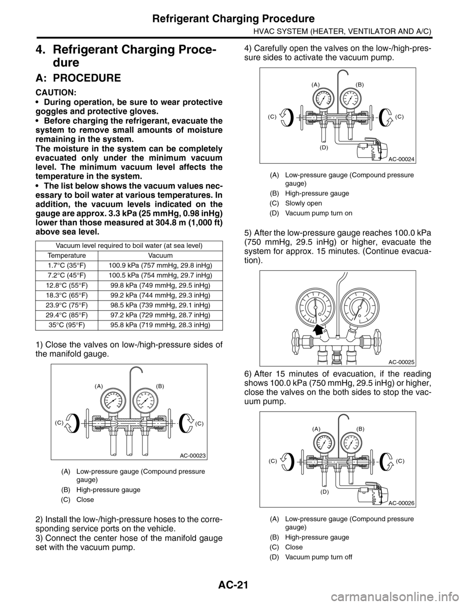
1) Close the valves on low-/high-pressure sides of
the manifold gauge.
2) Install the low-/high-pressure hoses to the corre-
sponding service ports on the vehicle.
3) Connect the center hose of the manifold gauge
set with the vacuum pump.
4) Carefully open the valves on the low-/high-pres-
sure sides to activate the vacuum pump.
5) After the low-pressure gauge reaches 100.0 kPa
(750 mmHg, 29.5 inHg) or higher, evacuate the
system for approx. 15 minutes. (Continue evacua-
tion).
6) After 15 minutes of evacuation, if the reading
shows 100.0 kPa (750 mmHg, 29.5 inHg) or higher,
close the valves on the both sides to stop the vac-
uum pump.
Va c u u m l eve l r e q u i r e d t o b o i l w a t e r ( a t s e a l eve l )
Te m p e r a t u r e Va c u u m
1.7°C (35°F) 100.9 kPa (757 mmHg, 29.8 inHg)
7.2°C (45°F) 100.5 kPa (754 mmHg, 29.7 inHg)
12.8°C (55°F) 99.8 kPa (749 mmHg, 29.5 inHg)
18.3°C (65°F) 99.2 kPa (744 mmHg, 29.3 inHg)
23.9°C (75°F) 98.5 kPa (739 mmHg, 29.1 inHg)
29.4°C (85°F) 97.2 kPa (729 mmHg, 28.7 inHg)
35°C (95°F) 95.8 kPa (719 mmHg, 28.3 inHg)
(A) Low-pressure gauge (Compound pressure
gauge)
(B) High-pressure gauge
(C) Close
AC-00023
(A) (B)
(C)(C)
(A) Low-pressure gauge (Compound pressure
gauge)
(B) High-pressure gauge
(C) Slowly open
(D) Vacuum pump turn on
(A) Low-pressure gauge (Compound pressure
gauge)
(B) High-pressure gauge
(C) Close
(D) Vacuum pump turn off
AC-00024
(A) (B)
(D)
(C)(C)
AC-00025
AC-00026
(A) (B)
(D)
(C)(C)
Page 350 of 2453
AC-24
Refrigerant Leak Check
HVAC SYSTEM (HEATER, VENTILATOR AND A/C)
5. Refrigerant Leak Check
A: INSPECTION
1) At engine speed below 1500rpm, operate the A/
C system for approx. 10 minutes, and confirm that
the high-side pressure shows at least 690 kPa
(7.03 kg/cm2, 100 psi). Then stop the engine to
start the leak test.
2) Starting from the connection between high-pres-
sure pipe and evaporator, check the system for
leaks along the high-pressure side through the
compressor. The following items must be checked
thoroughly.
3) Check the joint and seam between pressure
switch (dual switch) and high-pressure pipe.
4) Check the connections between condenser and
pipes, and welded joints on the condenser.
The leak tester may detect the oil on the condenser
fins as a leak.
5) Check the joint between compressor and hoses.
6) Check the machined area of the compressor and
other joints on the compressor.
7) Check the compressor shaft seal at the area
near the center of compressor clutch pulley.
Some shaft seals show a slight amount of leakage,
about 3 g (0.1 oz) per year. This is not a problem.
8) Starting from the connection between low-pres-
sure pipe and evaporator, check the system for
leakage along the low-pressure side through the
compressor. The following items must be checked
thoroughly.
•Connection between 2 parts
•Connection between pipe and plate
•Connection between pipes
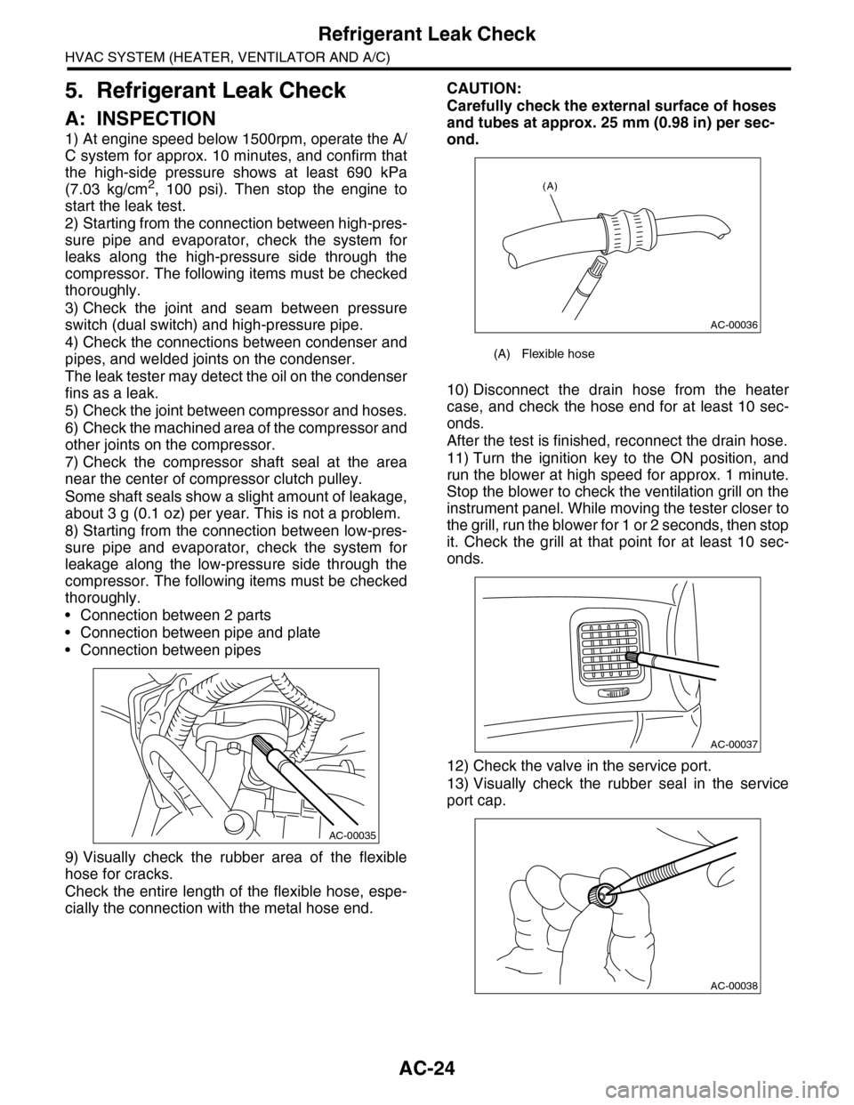
9) Visually check the rubber area of the flexible
hose for cracks.
Check the entire length of the flexible hose, espe-
cially the connection with the metal hose end.
CAUTION:
Carefully check the external surface of hoses
and tubes at approx. 25 mm (0.98 in) per sec-
ond.
10) Disconnect the drain hose from the heater
case, and check the hose end for at least 10 sec-
onds.
After the test is finished, reconnect the drain hose.
11) Turn the ignition key to the ON position, and
run the blower at high speed for approx. 1 minute.
Stop the blower to check the ventilation grill on the
instrument panel. While moving the tester closer to
the grill, run the blower for 1 or 2 seconds, then stop
it. Check the grill at that point for at least 10 sec-
onds.
12) Check the valve in the service port.
13) Visually check the rubber seal in the service
port cap.
AC-00035
(A) Flexible hose
AC-00036
(A)
AC-00037
AC-00038
Page 359 of 2453
AC-33
Compressor
HVAC SYSTEM (HEATER, VENTILATOR AND A/C)
14.Compressor
A: INSPECTION
1. MAGNETIC CLUTCH CLEARANCE
Check the clearance of the entire circumference
around the drive plate and pulley.
Standard:
0.45±0.15 mm (0.0177±0.0059 in)
2. MAGNETIC CLUTCH OPERATION
1) Disconnect the compressor connector.
2) Connect the positive (+) lead from the battery to
the compressor connector terminal, and the nega-
tive (–) lead to the compressor body.
3) Check the magnet clutch engagement.
If there is a problem, replace the compressor.
B: REMOVAL
1) Perform the compressor oil return operation.
2) Turn the A/C switch to OFF and stop the engine.
3) Using the refrigerant recovery system, dis-
charge refrigerant.
4) Disconnect the ground cable from battery.
5) Remove the V-belts.
6) Remove the generator.
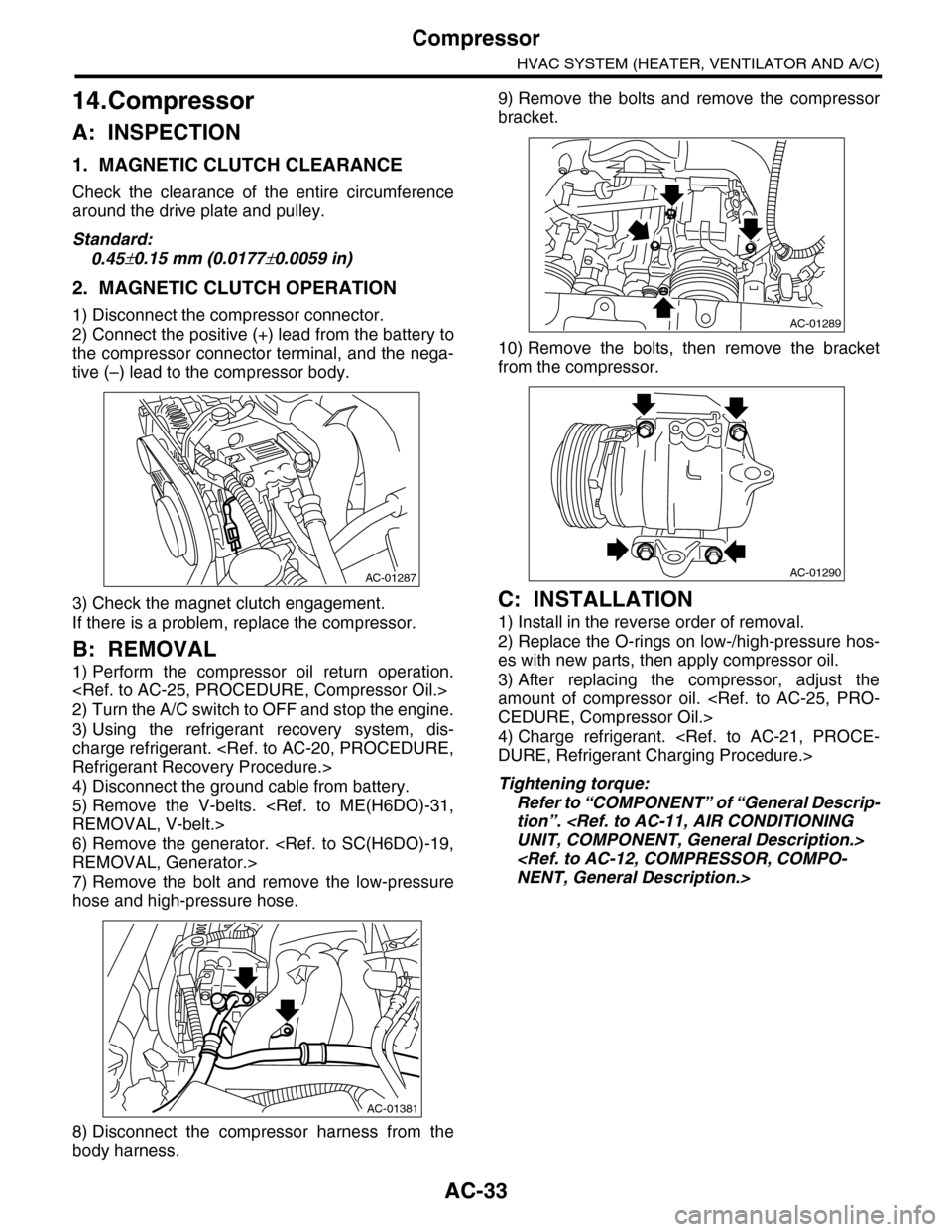
7) Remove the bolt and remove the low-pressure
hose and high-pressure hose.
8) Disconnect the compressor harness from the
body harness.
9) Remove the bolts and remove the compressor
bracket.
10) Remove the bolts, then remove the bracket
from the compressor.
C: INSTALLATION
1) Install in the reverse order of removal.
2) Replace the O-rings on low-/high-pressure hos-
es with new parts, then apply compressor oil.
3) After replacing the compressor, adjust the
amount of compressor oil.
4) Charge refrigerant.
Tightening torque:
Refer to “COMPONENT” of “General Descrip-
tion”.
AC-01287
AC-01381
AC-01289
AC-01290
Page 360 of 2453
AC-34
Condenser
HVAC SYSTEM (HEATER, VENTILATOR AND A/C)
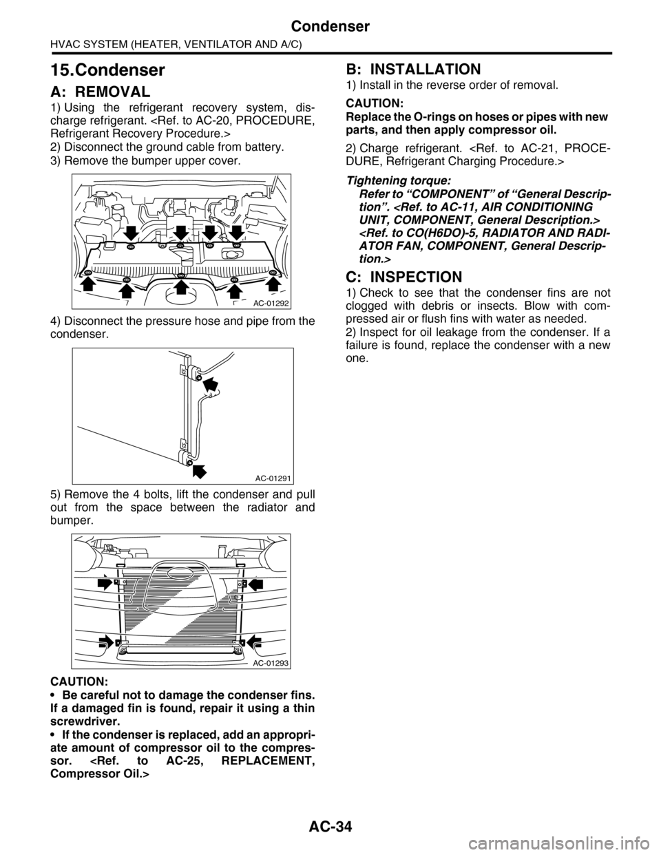
15.Condenser
A: REMOVAL
1) Using the refrigerant recovery system, dis-
charge refrigerant.
2) Disconnect the ground cable from battery.
3) Remove the bumper upper cover.
4) Disconnect the pressure hose and pipe from the
condenser.
5) Remove the 4 bolts, lift the condenser and pull
out from the space between the radiator and
bumper.
CAUTION:
•Be careful not to damage the condenser fins.
If a damaged fin is found, repair it using a thin
screwdriver.
•If the condenser is replaced, add an appropri-
ate amount of compressor oil to the compres-
sor.
B: INSTALLATION
1) Install in the reverse order of removal.
CAUTION:
Replace the O-rings on hoses or pipes with new
parts, and then apply compressor oil.
2) Charge refrigerant.
Tightening torque:
Refer to “COMPONENT” of “General Descrip-
tion”.
tion.>
C: INSPECTION
1) Check to see that the condenser fins are not
clogged with debris or insects. Blow with com-
pressed air or flush fins with water as needed.
2) Inspect for oil leakage from the condenser. If a
failure is found, replace the condenser with a new
one.
AC-01292
AC-01291
AC-01293
Page 441 of 2453
IDI-2
General Description
INSTRUMENTATION/DRIVER INFO
1. General Description
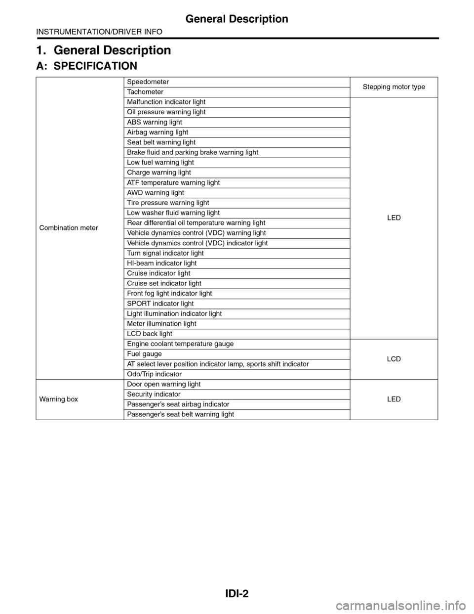
A: SPECIFICATION
Combination meter
SpeedometerStepping motor typeTa c h o m e t e r
Malfunction indicator light
LED
Oil pressure warning light
ABS warning light
Airbag warning light
Seat belt warning light
Brake fluid and parking brake warning light
Low fuel warning light
Charge warning light
AT F t e m p e r a t u r e w a r n i n g l i g h t
AW D war n in g l i gh t
Tire pressure warning light
Low washer fluid warning light
Rear differential oil temperature warning light
Ve h i c l e d y n a m i c s c o n t r o l ( V D C ) w a r n i n g l i g h t
Ve h i c l e d y n a m i c s c o n t r o l ( V D C ) i n d i c a t o r l i g h t
Tu r n s i g n a l i n d i c a t o r l i g h t
HI-beam indicator light
Cruise indicator light
Cruise set indicator light
Fr o nt fog li g ht i nd i ca to r li g ht
SPORT indicator light
Light illumination indicator light
Meter illumination light
LCD back light
Engine coolant temperature gauge
LCDFuel gauge
AT s e l e c t l e v e r p o s i t i o n i n d i c a t o r l a m p , s p o r t s s h i f t i n d i c a t o r
Odo/Trip indicator
Wa r ni n g b ox
Door open warning light
LEDSecurity indicator
Passenger’s seat airbag indicator
Passenger’s seat belt war ning light