rear seat SUBARU TRIBECA 2009 1.G Service Workshop Manual
[x] Cancel search | Manufacturer: SUBARU, Model Year: 2009, Model line: TRIBECA, Model: SUBARU TRIBECA 2009 1.GPages: 2453, PDF Size: 46.32 MB
Page 10 of 2453
AB-11
Airbag Connector
AIRBAG SYSTEM
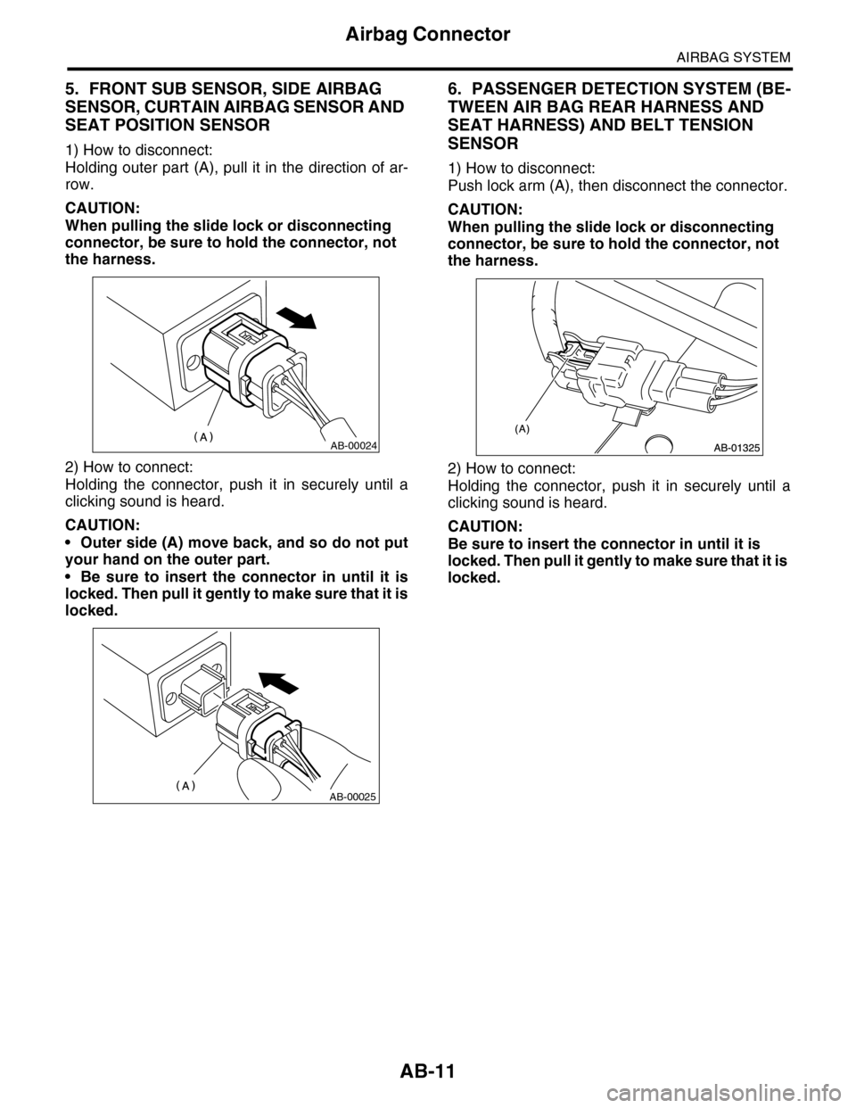
5. FRONT SUB SENSOR, SIDE AIRBAG
SENSOR, CURTAIN AIRBAG SENSOR AND
SEAT POSITION SENSOR
1) How to disconnect:
Holding outer part (A), pull it in the direction of ar-
row.
CAUTION:
When pulling the slide lock or disconnecting
connector, be sure to hold the connector, not
the harness.
2) How to connect:
Holding the connector, push it in securely until a
clicking sound is heard.
CAUTION:
•Outer side (A) move back, and so do not put
your hand on the outer part.
•Be sure to insert the connector in until it is
locked. Then pull it gently to make sure that it is
locked.
6. PASSENGER DETECTION SYSTEM (BE-
TWEEN AIR BAG REAR HARNESS AND
SEAT HARNESS) AND BELT TENSION
SENSOR
1) How to disconnect:
Push lock arm (A), then disconnect the connector.
CAUTION:
When pulling the slide lock or disconnecting
connector, be sure to hold the connector, not
the harness.
2) How to connect:
Holding the connector, push it in securely until a
clicking sound is heard.
CAUTION:
Be sure to insert the connector in until it is
locked. Then pull it gently to make sure that it is
locked.
AB-00024
AB-00025
Page 11 of 2453
AB-12
Inspection Locations After a Collision
AIRBAG SYSTEM
3. Inspection Locations After a
Collision
A: REPLACEMENT
Replace the following parts when the airbag is de-
ployed.
1. FRONT COLLISION
1) Driver’s airbag module
2) Passenger’s airbag module
3) Driver’s seat belt (Pretensioner)
4) Passenger’s seat belt (Pretensioner)
5) Airbag control module
6) Front sub sensor (L/R)
7) Roll connector
8) Instrument panel (for integrating with passen-
ger’s airbag module)
9) Passenger side seat cushion pad and frame as-
sembly
2. SIDE COLLISION
1) Airbag control module
2) Side airbag module (operating side seat back-
rest)
3) Side airbag sensor (operating side)
4) Curtain airbag module (operating side)
5) Curtain airbag sensor (operating side)
3. INSPECTION OF OTHER PARTS
Check for the following parts, and replace the dam-
aged parts with new parts.
1) Steering wheel and steering shaft
Check the steering shaft for mounting conditions
and deflection of front and rear, upward and down-
ward directions, and deflection of front and rear di-
rection with tilt lever released. (After a collision,
there is a good chance that the shock absorbing
part of steering shaft may have operated.)
2) Check the connectors of airbag module, preten-
sioner, etc. for damage, and also check each har-
ness for pinch and connector damage. Replace the
harness as a unit if damage is found.
3) Check the seat cushion frame, backrest, seat rail
and headrest for deformation, distortion, crack, and
installing condition and play.
4) For passengers seat, replace the seat cushion
frame assembly with new one if the seat cushion
frame is deformed or cracked.
5) If there are tears or loosening in the passenger
side seat cushion cover, it may interfere with the
proper operation of the passenger detection sys-
tem. Replace with a new cushion cover.
6) Be sure to perform the system calibration for the
occupant detection system after removing or re-
placing the passenger seat cushion cover. Failure
to do so may cause improper operation of the pas-
senger detection system.
TION, Subaru Select Monitor.>
7) Use the Subaru Select Monitor to check whether
the drivers seat position sensor and the drivers and
the front left/right seat belt buckle switches are op-
erating normally.
B: INSPECTION
If the vehicle is involved in a collision, even if it is a
slight collision, be sure to check the following sys-
tems.
1. DRIVER’S AIRBAG MODULE
1) Check for the following, and replace the dam-
aged parts with new parts.
•Airbag module is cracked or deformed.
•Harness and/or connector is cracked, deformed
or open. Harness wire is exposed.
•The module surface is fouled with grease, oil,
water or cleaning solvent.
2) When installing a new driver’s airbag module,
check for the following, and replace the damaged
parts with new parts.
•The steering wheel is in the way, making it diffi-
cult to install the airbag module.
•The clearance between the driver’s airbag mod-
ule and steering wheel is not constant.
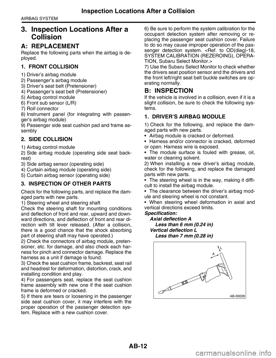
•When steering wheel deformation in axial and
vertical directions exceed limits.
Specification:
Axial deflection A
Less than 6 mm (0.24 in)
Vertical deflection L
Less than 7 mm (0.28 in)
AB-00028
L
A
Page 30 of 2453
AB(diag)-6
General Description
AIRBAG SYSTEM (DIAGNOSTICS)
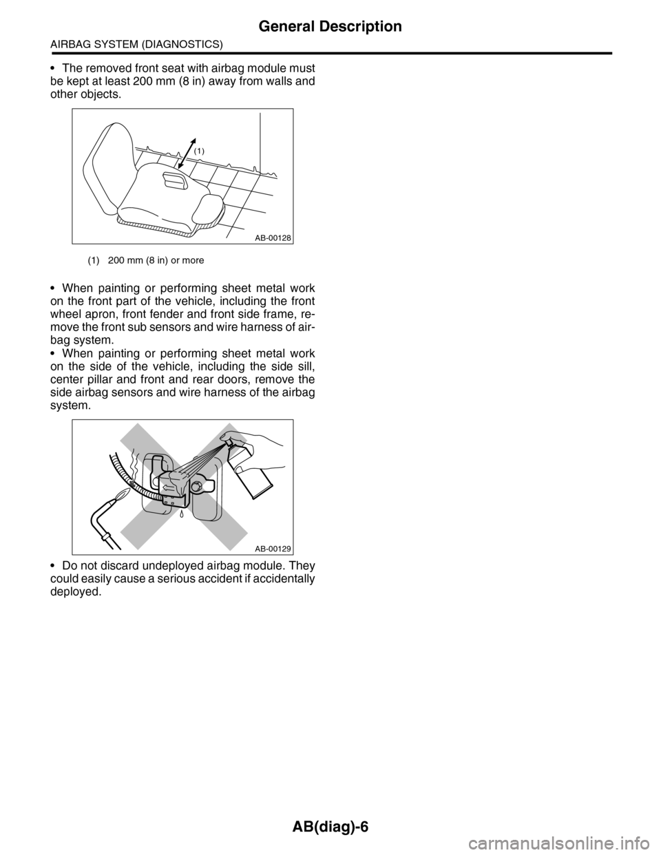
•The removed front seat with airbag module must
be kept at least 200 mm (8 in) away from walls and
other objects.
•When painting or performing sheet metal work
on the front part of the vehicle, including the front
wheel apron, front fender and front side frame, re-
move the front sub sensors and wire harness of air-
bag system.
•When painting or performing sheet metal work
on the side of the vehicle, including the side sill,
center pillar and front and rear doors, remove the
side airbag sensors and wire harness of the airbag
system.
•Do not discard undeployed airbag module. They
could easily cause a serious accident if accidentally
deployed.
(1) 200 mm (8 in) or more
AB-00128
(1)
AB-00129
Page 48 of 2453
AB(diag)-24
Electrical Component Location
AIRBAG SYSTEM (DIAGNOSTICS)
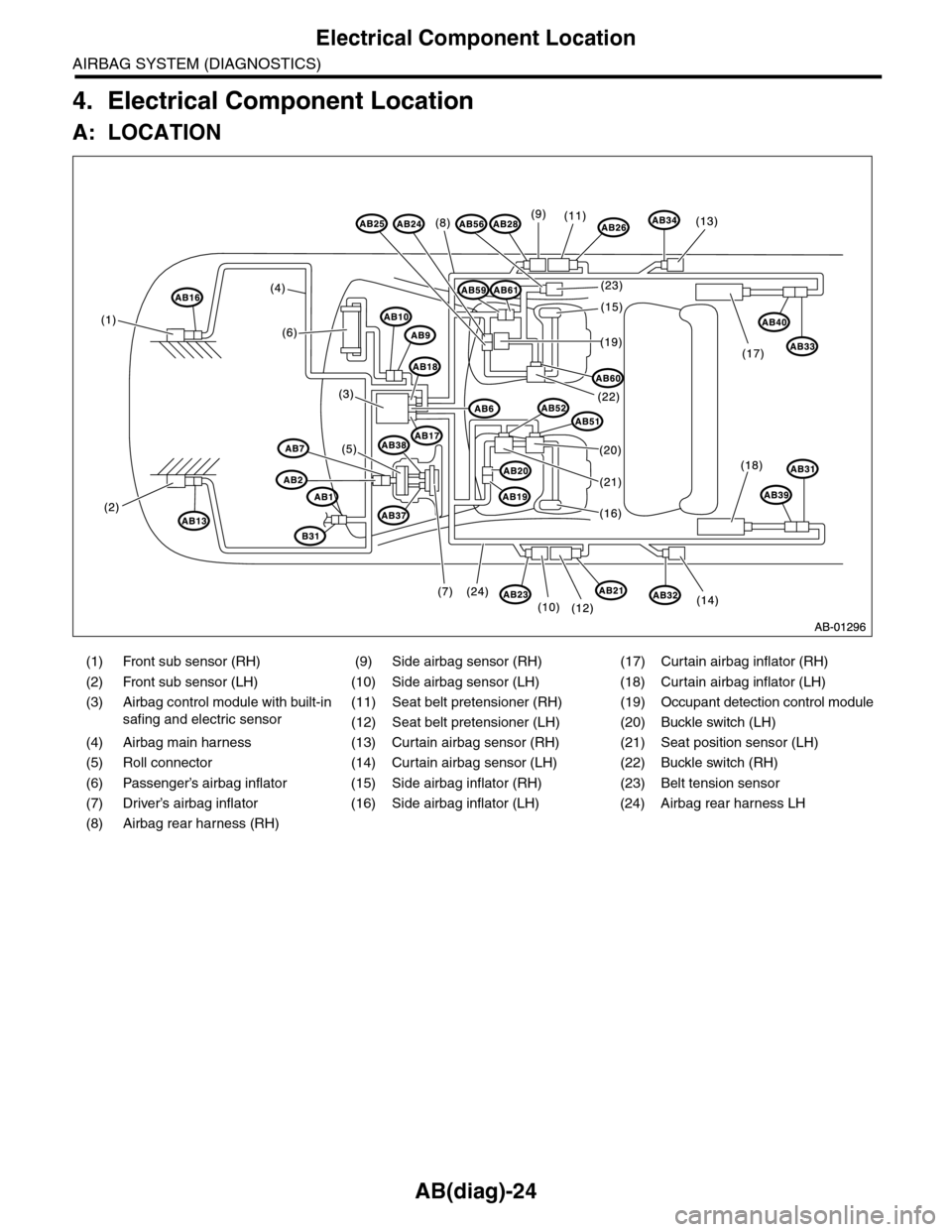
4. Electrical Component Location
A: LOCATION
(1) Front sub sensor (RH) (9) Side airbag sensor (RH) (17) Curtain airbag inflator (RH)
(2) Front sub sensor (LH) (10) Side airbag sensor (LH) (18) Curtain airbag inflator (LH)
(3)
Airbag control module with built-in
safing and electric sensor
(11) Seat belt pretensioner (RH) (19) Occupant detection control module
(12) Seat belt pretensioner (LH) (20) Buckle switch (LH)
(4) Airbag main harness (13) Curtain airbag sensor (RH) (21) Seat position sensor (LH)
(5) Roll connector (14) Curtain airbag sensor (LH) (22) Buckle switch (RH)
(6) Passenger’s airbag inflator (15) Side airbag inflator (RH) (23) Belt tension sensor
(7) Driver’s airbag inflator (16) Side airbag inflator (LH) (24) Airbag rear harness LH
(8) Airbag rear harness (RH)
Page 56 of 2453
AB(diag)-32
Subaru Select Monitor
AIRBAG SYSTEM (DIAGNOSTICS)
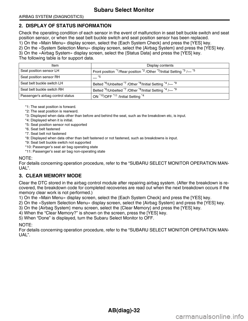
2. DISPLAY OF STATUS INFORMATION
Check the operating condition of each sensor in the event of malfunction in seat belt buckle switch and seat
position sensor, or when the seat belt buckle switch and seat position sensor has been replaced.
1) On the «Main Menu» display screen, select the {Each System Check} and press the [YES] key.
2) On the «System Selection Menu» display screen, select the {Airbag System} and press the [YES] key.
3) On the «Airbag System» display screen, select the {Status Data} and press the [YES] key.
The following table is for support data.
*1: The seat position is forward.
*2: The seat position is rearward.
*3: Displayed when data other than before and behind the seat, such as the breakdown etc, is input.
*4: Displayed when it is initial.
*5: Seat position sensor not supported
*6. Seat belt fastened
*7. Seat belt not fastened
*8: Displayed when data other than belt fastened or not fastened, such as breakdowns is input.
*9: Seat belt buckle switch not supported
*10: Passenger’s seat air bag operating state
*11: Passenger’s seat air bag non-operating state
NOTE:
For details concerning operation procedure, refer to the “SUBARU SELECT MONITOR OPERATION MAN-
UAL”.
3. CLEAR MEMORY MODE
Clear the DTC stored in the airbag control module after repairing airbag system. (After the breakdown is re-
covered, the breakdown code for completed recoveries are read out when the next breakdown occurs if the
memory clear work is not performed.)
1) On the «Main Menu» display screen, select the {Each System Check} and press the [YES] key.
2) On the «System Selection Menu» display screen, select the {Airbag System} and press the [YES] key.
3) On the {Airbag System} menu screen, select the {Clear Memory} and press the [YES] key.
4) When the “Clear Memory?” is shown on the screen, press the [YES] key.
5) When “Done” is displayed, turn the Subaru Select Monitor to OFF.
NOTE:
For details concerning operation procedure, refer to the “SUBARU SELECT MONITOR OPERATION MAN-
UAL”.
Item Display contents
Seat position sensor LHFr o nt p os it i on *1/Rear position *2 /Other *3/Initial Setting *3 /–– *5
Seat position sensor RH–– *5
Seat belt buckle switch LHBelted *6/Unbelted *7 /Other *8/Initial Setting *4 /–– *9
Seat belt buckle switch RHBelted *6/Unbelted *7 /Other *8/Initial Setting *4 /–– *9
Passenger’s airbag control statusON *10/OFF *11 /Initial Setting *4
Page 69 of 2453
AB(diag)-45
List of Diagnostic Trouble Code (DTC)
AIRBAG SYSTEM (DIAGNOSTICS)
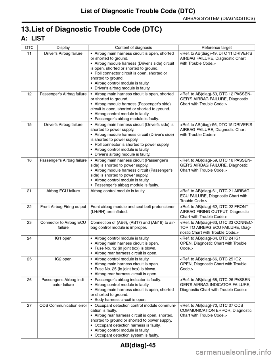
13.List of Diagnostic Trouble Code (DTC)
A: LIST
DTC Display Content of diagnosis Reference target
11 Driver’s Airbag failure • Airbag main harness circuit is open, shorted
or shorted to ground.
•Airbag module harness (Driver's side) circuit
is open, shorted or shorted to ground.
•Roll connector circuit is open, shorted or
shorted to ground.
•Airbag control module is faulty.
•Driver's airbag module is faulty.
with Trouble Code.>
12 Passenger's Airbag failure • Airbag main harness circuit is open, shorted
or shorted to ground.
•Airbag module harness (Passenger's side)
circuit is open, shorted or shorted to ground.
•Airbag control module is faulty.
•Passenger's airbag module is faulty.
Chart with Trouble Code.>
15 Driver’s Airbag failure • Airbag main harness circuit (Driver’s side) is
shorted to power supply.
•Airbag module harness circuit (Driver’s side)
is shorted to power supply.
•Roll connector is shorted to power supply.
•Airbag control module is faulty.
•Driver’s airbag module is faulty.
with Trouble Code.>
16 Passenger's Airbag failure • Airbag main harness circuit (Passenger's
side) is shorted to power supply.
•Airbag module harness circuit (Passenger's
side) is shorted to power supply.
•Airbag control module is faulty.
•Passenger's airbag module is faulty.
Chart with Trouble Code.>
21 Airbag ECU failure Airbag control module is faulty.
Tr o u b l e C o d e . >
22 Front Airbag Firing output Front airbag module and seat belt pretensioner
(LH/RH) are inflated.
Chart with Trouble Code.>
23 Connector to Airbag ECU
failure
Connection of (AB6), (AB17) and (AB18) to air-
bag control module is improper.
nostic Chart with Trouble Code.>
24 IG1 open • Airbag control module is faulty.
•Airbag main harness circuit is open.
•Fuse No. 12 (in joint box) is blown.
•Airbag rear harness circuit is open.
Code.>
25 IG2 open • Airbag control module is faulty.
•Airbag main harness circuit is open.
•Fuse No. 25 (in joint box) is blown.
•Airbag rear harness circuit is open.
Code.>
26 Passenger's Airbag indi-
cator failure
•Passenger's airbag indicator is faulty.
•Airbag control module is faulty.
•Airbag main harness circuit is open, shorted
or shorted to ground.
•Body harness circuit is open.
Diagnostic Chart with Trouble Code.>
27 ODS Communication error • Occupant detection control module communi-
cation is faulty.
•Airbag rear harness circuit is open, shorted,
shorted to ground or shorted to power supply.
•Occupant detection harness is faulty.
•Airbag control module is faulty.
•Occupant detection system is faulty.
Chart with Trouble Code.>
Page 70 of 2453
AB(diag)-46
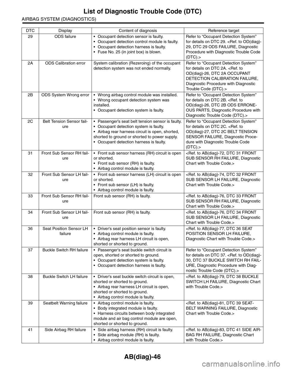
List of Diagnostic Trouble Code (DTC)
AIRBAG SYSTEM (DIAGNOSTICS)
29 ODS failure • Occupant detection sensor is faulty.
•Occupant detection control module is faulty.
•Occupant detection harness is faulty.
•Fuse No. 25 (in joint box) is blown.
Refer to “Occupant Detection System”
for details on DTC 29.
Procedure with Diagnostic Trouble Code
(DTC).>
2A ODS Calibration error System calibration (Rezeroing) of the occupant
detection system was not ended normally.
Refer to “Occupant Detection System”
for details on DTC 2A.
DETECTION CALIBRATION FAILURE,
Diagnostic Procedure with Diagnostic
Tr o u b l e C o d e ( D T C ) . >
2B ODS System Wrong error • Wrong airbag control module was installed.
•Wrong occupant detection system was
installed.
•Occupant detection system is faulty.
Refer to “Occupant Detection System”
for details on DTC 2B.
OUS PARTS, Diagnostic Procedure with
Diagnostic Trouble Code (DTC).>
2C Belt Tension Sensor fail-
ure
•Passenger’s seat belt tension sensor is faulty.
•Occupant detection system is faulty.
•Airbag rear harness circuit is open, shorted,
shorted to ground or shorted to power supply.
•Occupant detection harness is faulty.
Refer to “Occupant Detection System”
for details on DTC 2C.
SENSOR FAILURE, Diagnostic Proce-
dure with Diagnostic Trouble Code
(DTC).>
31 Front Sub Sensor RH fail-
ure
•Front sub sensor harness (RH) circuit is open
or shorted.
•Front sub sensor (RH) is faulty.
•Airbag control module is faulty.
Chart with Trouble Code.>
32 Front Sub Sensor LH fail-
ure
•Front sub sensor harness (LH) circuit is open
or shorted.
•Front sub sensor (LH) is faulty.
•Airbag control module is faulty.
Chart with Trouble Code.>
33 Front Sub Sensor RH fail-
ure
Fr o nt su b se ns or ( RH) i s fa u lt y. < Re f. t o A B ( d ia g ) - 76 , D TC 3 3 F RONT
SUB SENSOR RH FAILURE, Diagnostic
Chart with Trouble Code.>
34 Front Sub Sensor LH fail-
ure
Fr o nt su b se ns or ( RH) i s fa u lt y. < Re f. t o A B ( d ia g ) - 76 , D TC 3 4 F RONT
SUB SENSOR LH FAILURE, Diagnostic
Chart with Trouble Code.>
36 Seat Position Sensor LH
failure
•Driver's seat position sensor is faulty.
•Airbag control module is faulty.
•Airbag rear harness LH circuit is open,
shorted or shorted to ground.
Diagnostic Chart with Trouble Code.>
37 Buckle Switch RH failure • Passenger's seat buckle switch circuit is
open, shorted or shorted to ground.
•Occupant detection system is faulty.
•Occupant detection harness is faulty.
Refer to “Occupant Detection System”
for details on DTC 37.
URE, Diagnostic Procedure with Diag-
nostic Trouble Code (DTC).>
38 Buckle Switch LH failure • Driver's seat buckle switch circuit is open,
shorted or shorted to ground.
•Airbag rear harness LH circuit is open,
shorted or shorted to ground.
•Airbag control module is faulty.
with Trouble Code.>
39 Seatbelt Warning failure • Airbag control module is faulty.
•Body integrated module is faulty.
•Harness circuits between body integrated
module and air bag control module are open,
shorted or shorted to ground.
Chart with Trouble Code.>
41 Side Airbag RH failure • Side airbag harness (RH) circuit is faulty.
•Side airbag module (RH) is faulty.
•Airbag control module is faulty.
with Trouble Code.>
DTC Display Content of diagnosis Reference target
Page 94 of 2453
AB(diag)-70
Diagnostic Chart with Trouble Code
AIRBAG SYSTEM (DIAGNOSTICS)
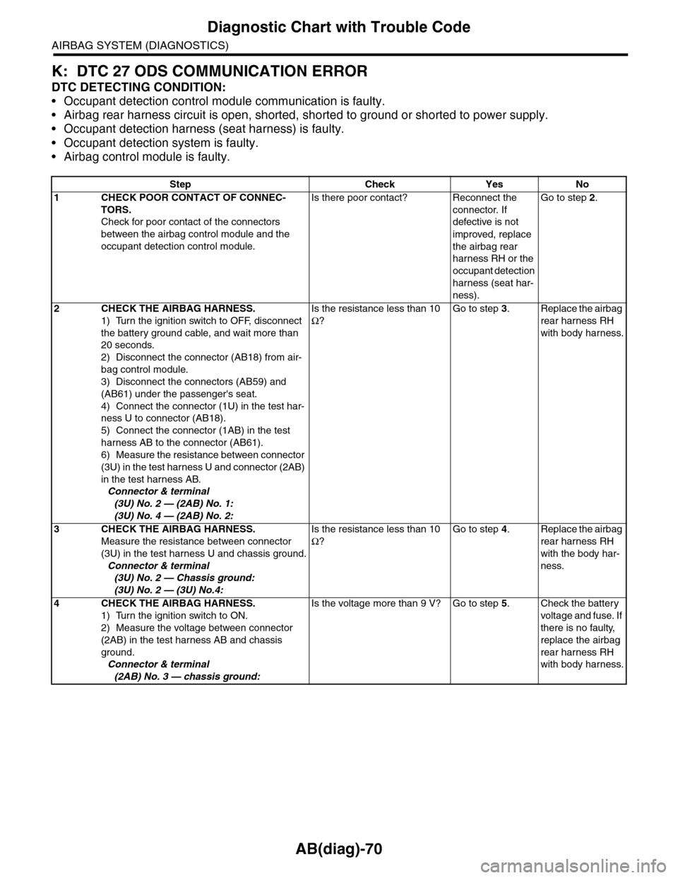
K: DTC 27 ODS COMMUNICATION ERROR
DTC DETECTING CONDITION:
•Occupant detection control module communication is faulty.
•Airbag rear harness circuit is open, shorted, shorted to ground or shorted to power supply.
•Occupant detection harness (seat harness) is faulty.
•Occupant detection system is faulty.
•Airbag control module is faulty.
Step Check Yes No
1CHECK POOR CONTACT OF CONNEC-
TORS.
Check for poor contact of the connectors
between the airbag control module and the
occupant detection control module.
Is there poor contact? Reconnect the
connector. If
defective is not
improved, replace
the airbag rear
harness RH or the
occupant detection
harness (seat har-
ness).
Go to step 2.
2CHECK THE AIRBAG HARNESS.
1) Turn the ignition switch to OFF, disconnect
the battery ground cable, and wait more than
20 seconds.
2) Disconnect the connector (AB18) from air-
bag control module.
3) Disconnect the connectors (AB59) and
(AB61) under the passenger's seat.
4) Connect the connector (1U) in the test har-
ness U to connector (AB18).
5) Connect the connector (1AB) in the test
harness AB to the connector (AB61).
6) Measure the resistance between connector
(3U) in the test harness U and connector (2AB)
in the test harness AB.
Connector & terminal
(3U) No. 2 — (2AB) No. 1:
(3U) No. 4 — (2AB) No. 2:
Is the resistance less than 10
Ω?
Go to step 3.Replace the airbag
rear harness RH
with body harness.
3CHECK THE AIRBAG HARNESS.
Measure the resistance between connector
(3U) in the test harness U and chassis ground.
Connector & terminal
(3U) No. 2 — Chassis ground:
(3U) No. 2 — (3U) No.4:
Is the resistance less than 10
Ω?
Go to step 4.Replace the airbag
rear harness RH
with the body har-
ness.
4CHECK THE AIRBAG HARNESS.
1) Turn the ignition switch to ON.
2) Measure the voltage between connector
(2AB) in the test harness AB and chassis
ground.
Connector & terminal
(2AB) No. 3 — chassis ground:
Is the voltage more than 9 V? Go to step 5.Check the battery
voltage and fuse. If
there is no faulty,
replace the airbag
rear harness RH
with body harness.
Page 95 of 2453
AB(diag)-71
Diagnostic Chart with Trouble Code
AIRBAG SYSTEM (DIAGNOSTICS)
L: DTC 29 ODS FAILURE
NOTE:
Refer to “Occupant Detection System” for details on DTC 29.
M: DTC 2A OCCUPANT DETECTION CALIBRATION FAILURE
NOTE:
Refer to “Occupant Detection System” for details on DTC 2A.
N: DTC 2B ODS ERRONEOUS PARTS
NOTE:
Refer to “Occupant Detection System” for details on DTC 2B.
O: DTC 2C BELT TENSION SENSOR FAILURE
NOTE:
Refer to “Occupant Detection System” for details on DTC 2C.
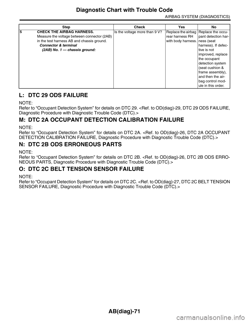
5CHECK THE AIRBAG HARNESS.
Measure the voltage between connector (2AB)
in the test harness AB and chassis ground.
Connector & terminal
(2AB) No. 1 — chassis ground:
Is the voltage more than 9 V? Replace the airbag
rear harness RH
with body harness.
Replace the occu-
pant detection har-
ness (seat
harness). If defec-
tive is not
improved, replace
the occupant
detection system
(seat cushion &
frame assembly),
and then the air-
bag control mod-
ule in this order.
Step Check Yes No
Page 101 of 2453
AB(diag)-77
Diagnostic Chart with Trouble Code
AIRBAG SYSTEM (DIAGNOSTICS)
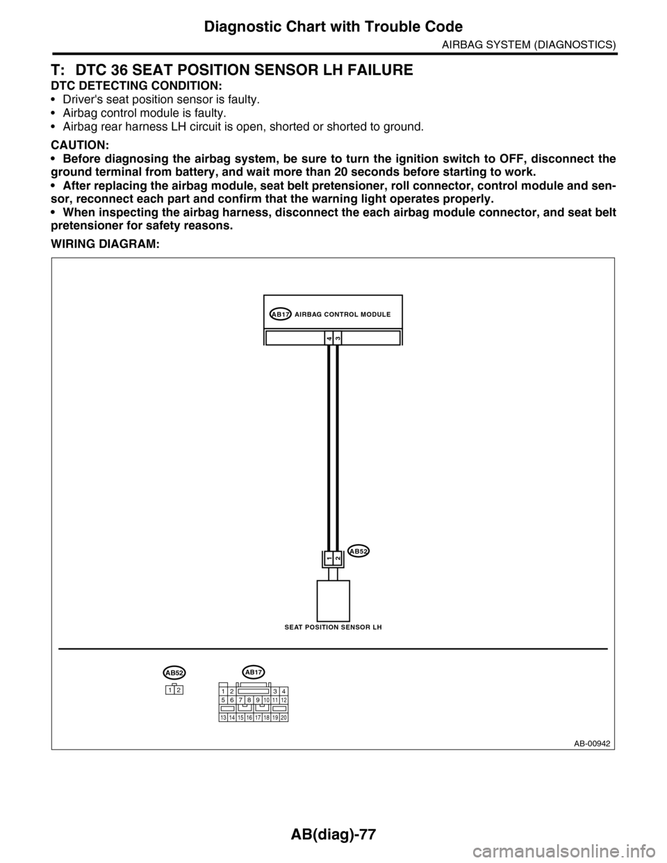
T: DTC 36 SEAT POSITION SENSOR LH FAILURE
DTC DETECTING CONDITION:
•Driver's seat position sensor is faulty.
•Airbag control module is faulty.
•Airbag rear harness LH circuit is open, shorted or shorted to ground.
CAUTION:
•Before diagnosing the airbag system, be sure to turn the ignition switch to OFF, disconnect the
ground terminal from battery, and wait more than 20 seconds before starting to work.
•After replacing the airbag module, seat belt pretensioner, roll connector, control module and sen-
sor, reconnect each part and confirm that the warning light operates properly.
•When inspecting the airbag harness, disconnect the each airbag module connector, and seat belt
pretensioner for safety reasons.
WIRING DIAGRAM:
AB-00942
AB17
AB52
43
1 2
AIRBAG CONTROL MODULE
SEAT POSITION SENSOR LH
AB52
12
AB17
12 345678910 11 12
13 14 15 16 17 18 19 20