self-diagnosis of combination meter SUBARU TRIBECA 2009 1.G Service Workshop Manual
[x] Cancel search | Manufacturer: SUBARU, Model Year: 2009, Model line: TRIBECA, Model: SUBARU TRIBECA 2009 1.GPages: 2453, PDF Size: 46.32 MB
Page 177 of 2453
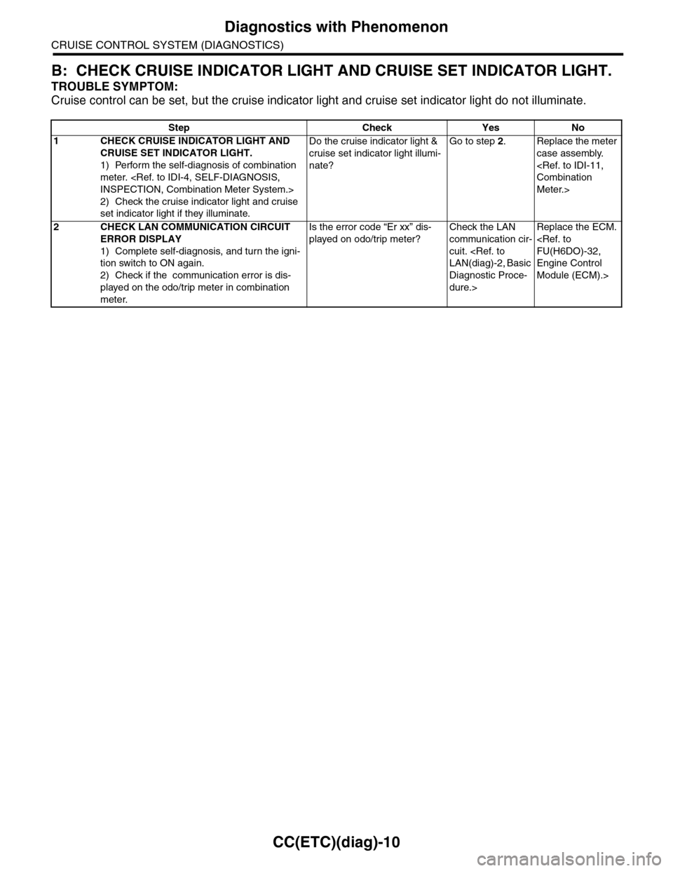
CC(ETC)(diag)-10
Diagnostics with Phenomenon
CRUISE CONTROL SYSTEM (DIAGNOSTICS)
B: CHECK CRUISE INDICATOR LIGHT AND CRUISE SET INDICATOR LIGHT.
TROUBLE SYMPTOM:
Cruise control can be set, but the cruise indicator light and cruise set indicator light do not illuminate.
Step Check Yes No
1CHECK CRUISE INDICATOR LIGHT AND
CRUISE SET INDICATOR LIGHT.
1) Perform the self-diagnosis of combination
meter.
2) Check the cruise indicator light and cruise
set indicator light if they illuminate.
Do the cruise indicator light &
cruise set indicator light illumi-
nate?
Go to step 2.Replace the meter
case assembly.
Meter.>
2CHECK LAN COMMUNICATION CIRCUIT
ERROR DISPLAY
1) Complete self-diagnosis, and turn the igni-
tion switch to ON again.
2) Check if the communication error is dis-
played on the odo/trip meter in combination
meter.
Is the error code “Er xx” dis-
played on odo/trip meter?
Check the LAN
communication cir-
cuit.
Diagnostic Proce-
dure.>
Replace the ECM.
Engine Control
Module (ECM).>
Page 443 of 2453
IDI-4
Combination Meter System
INSTRUMENTATION/DRIVER INFO
2. Combination Meter System
A: WIRING DIAGRAM
1. COMBINATION METER
B: INSPECTION
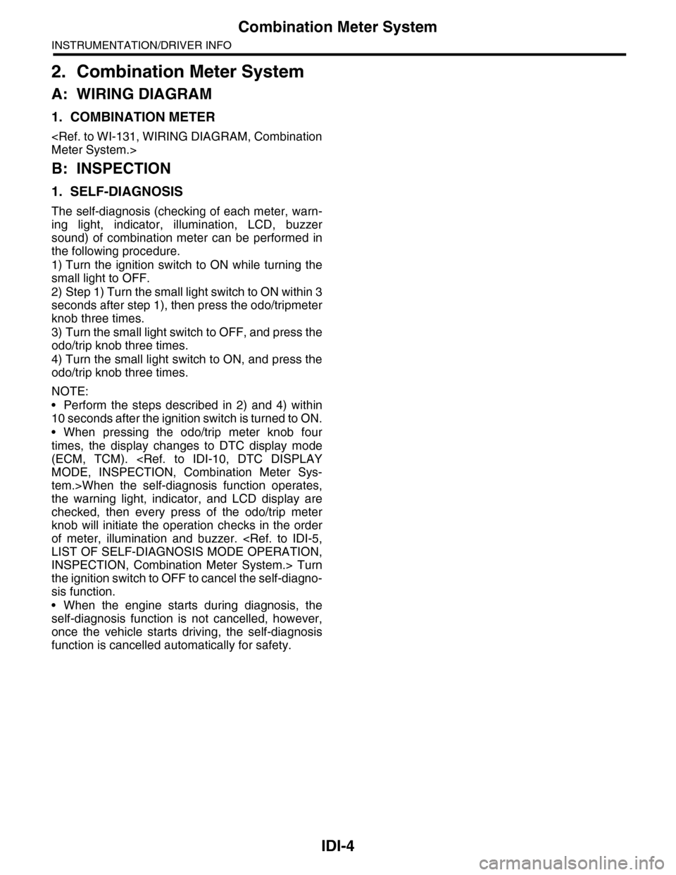
1. SELF-DIAGNOSIS
The self-diagnosis (checking of each meter, warn-
ing light, indicator, illumination, LCD, buzzer
sound) of combination meter can be performed in
the following procedure.
1) Turn the ignition switch to ON while turning the
small light to OFF.
2) Step 1) Turn the small light switch to ON within 3
seconds after step 1), then press the odo/tripmeter
knob three times.
3) Turn the small light switch to OFF, and press the
odo/trip knob three times.
4) Turn the small light switch to ON, and press the
odo/trip knob three times.
NOTE:
•Perform the steps described in 2) and 4) within
10 seconds after the ignition switch is turned to ON.
•When pressing the odo/trip meter knob four
times, the display changes to DTC display mode
(ECM, TCM).
tem.>When the self-diagnosis function operates,
the warning light, indicator, and LCD display are
checked, then every press of the odo/trip meter
knob will initiate the operation checks in the order
of meter, illumination and buzzer.
INSPECTION, Combination Meter System.> Turn
the ignition switch to OFF to cancel the self-diagno-
sis function.
•When the engine starts during diagnosis, the
self-diagnosis function is not cancelled, however,
once the vehicle starts driving, the self-diagnosis
function is cancelled automatically for safety.
Page 444 of 2453
IDI-5
Combination Meter System
INSTRUMENTATION/DRIVER INFO
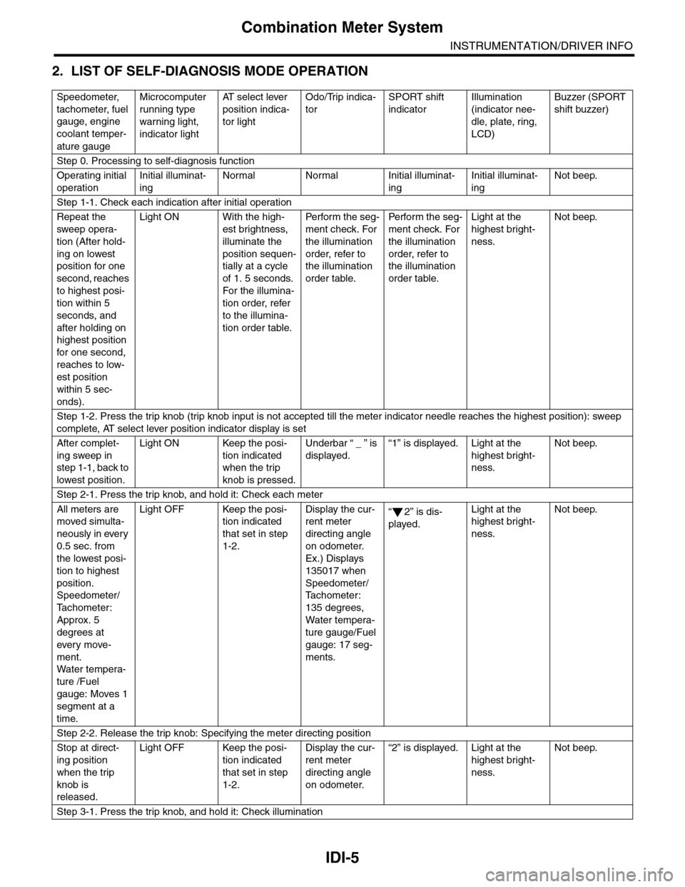
2. LIST OF SELF-DIAGNOSIS MODE OPERATION
Speedometer,
tachometer, fuel
gauge, engine
coolant temper-
ature gauge
Microcomputer
running type
warning light,
indicator light
AT s e l e c t l e v e r
position indica-
tor light
Odo/Trip indica-
tor
SPORT shift
indicator
Illumination
(indicator nee-
dle, plate, ring,
LCD)
Buzzer (SPORT
shift buzzer)
Step 0. Processing to self-diagnosis function
Operating initial
operation
Initial illuminat-
ing
Normal Normal Initial illuminat-
ing
Initial illuminat-
ing
Not beep.
Step 1-1. Check each indication after initial operation
Repeat the
sweep opera-
tion (After hold-
ing on lowest
position for one
second, reaches
to highest posi-
tion within 5
seconds, and
after holding on
highest position
for one second,
reaches to low-
est position
within 5 sec-
onds).
Light ON With the high-
est brightness,
illuminate the
position sequen-
tially at a cycle
of 1. 5 seconds.
For the illumina-
tion order, refer
to the illumina-
tion order table.
Pe r for m t he s eg -
ment check. For
the illumination
order, refer to
the illumination
order table.
Pe rfo r m t h e se g -
ment check. For
the illumination
order, refer to
the illumination
order table.
Light at the
highest bright-
ness.
Not beep.
Step 1-2. Press the trip knob (trip knob input is not accepted till the meter indicator needle reaches the highest position): sweep
complete, AT select lever position indicator display is set
After complet-
ing sweep in
step 1-1, back to
lowest position.
Light ON Keep the posi-
tion indicated
when the trip
knob is pressed.
Underbar “ _ ” is
displayed.
“1” is displayed. Light at the
highest bright-
ness.
Not beep.
Step 2-1. Press the trip knob, and hold it: Check each meter
All meters are
moved simulta-
neously in every
0.5 sec. from
the lowest posi-
tion to highest
position.
Speedometer/
Ta c h o m e t e r :
Approx. 5
degrees at
ever y move-
ment.
Wa t er t e mp er a-
ture /Fuel
gauge: Moves 1
segment at a
time.
Light OFF Keep the posi-
tion indicated
that set in step
1-2.
Display the cur-
rent meter
directing angle
on odometer.
Ex.) Displays
135017 when
Speedometer/
Ta c h o m e t e r :
135 degrees,
Water tempera-
ture gauge/Fuel
gauge: 17 seg-
ments.
“2” is dis-
played.
Light at the
highest bright-
ness.
Not beep.
Step 2-2. Release the trip knob: Specifying the meter directing position
Stop at direct-
ing position
when the trip
knob is
released.
Light OFF Keep the posi-
tion indicated
that set in step
1-2.
Display the cur-
rent meter
directing angle
on odometer.
“2” is displayed. Light at the
highest bright-
ness.
Not beep.
Step 3-1. Press the trip knob, and hold it: Check illumination
Page 445 of 2453
IDI-6
Combination Meter System
INSTRUMENTATION/DRIVER INFO
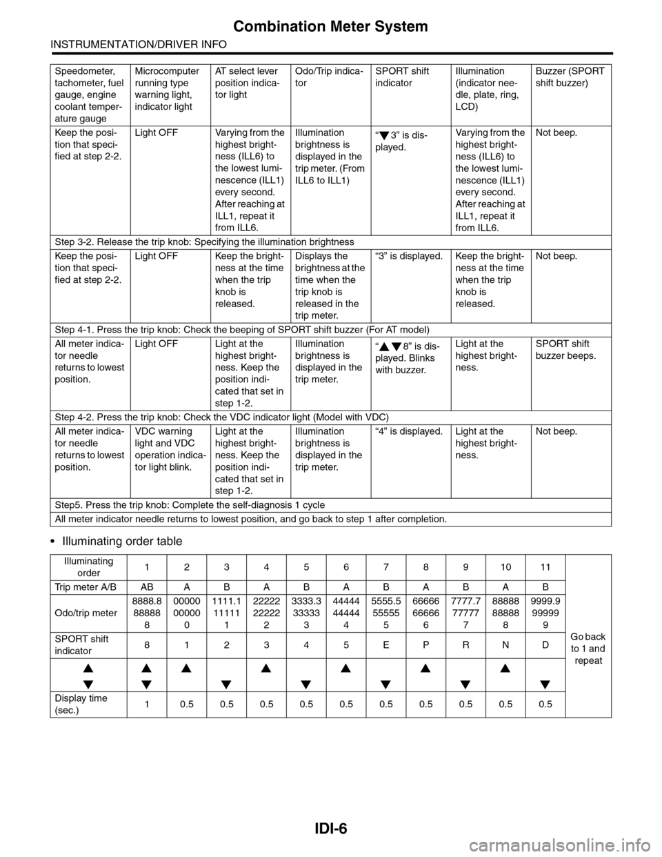
•Illuminating order table
Keep the posi-
tion that speci-
fied at step 2-2.
Light OFF Varying from the
highest bright-
ness (ILL6) to
the lowest lumi-
nescence (ILL1)
ever y second.
After reaching at
ILL1, repeat it
from ILL6.
Illumination
brightness is
displayed in the
trip meter. (From
ILL6 to ILL1)
“3” is dis-
played.
Va r y i n g f r o m t h e
highest bright-
ness (ILL6) to
the lowest lumi-
nescence (ILL1)
every second.
After reaching at
ILL1, repeat it
from ILL6.
Not beep.
Step 3-2. Release the trip knob: Specifying the illumination brightness
Keep the posi-
tion that speci-
fied at step 2-2.
Light OFF Keep the bright-
ness at the time
when the trip
knob is
released.
Displays the
brightness at the
time when the
trip knob is
released in the
trip meter.
“3” is displayed. Keep the bright-
ness at the time
when the trip
knob is
released.
Not beep.
Step 4-1. Press the trip knob: Check the beeping of SPORT shift buzzer (For AT model)
All meter indica-
tor needle
returns to lowest
position.
Light OFF Light at the
highest bright-
ness. Keep the
position indi-
cated that set in
step 1-2.
Illumination
brightness is
displayed in the
trip meter.
“8” is dis-
played. Blinks
with buzzer.
Light at the
highest bright-
ness.
SPORT shift
buzzer beeps.
Step 4-2. Press the trip knob: Check the VDC indicator light (Model with VDC)
All meter indica-
tor needle
returns to lowest
position.
VDC warning
light and VDC
operation indica-
tor light blink.
Light at the
highest bright-
ness. Keep the
position indi-
cated that set in
step 1-2.
Illumination
brightness is
displayed in the
trip meter.
“4” is displayed. Light at the
highest bright-
ness.
Not beep.
Step5. Press the trip knob: Complete the self-diagnosis 1 cycle
All meter indicator needle returns to lowest position, and go back to step 1 after completion.
Illuminating
order1234567891011
Tr i p m e t e r A / B A B A B A B A B A B A B
Go back
to 1 and
repeat
Odo/trip meter
8888.8
88888
8
00000
00000
0
1111.1
11111
1
22222
22222
2
3333.3
33333
3
44444
44444
4
5555.5
55555
5
66666
66666
6
7777.7
77777
7
88888
88888
8
9999.9
99999
9
SPORT shift
indicator812345EPRND
Display time
(sec.)10.50.50.50.50.50.50.50.50.50.5
Speedometer,
tachometer, fuel
gauge, engine
coolant temper-
ature gauge
Microcomputer
running type
warning light,
indicator light
AT s e l e c t l e v e r
position indica-
tor light
Odo/Trip indica-
tor
SPORT shift
indicator
Illumination
(indicator nee-
dle, plate, ring,
LCD)
Buzzer (SPORT
shift buzzer)
Page 491 of 2453
LAN(diag)-35
Diagnostic Procedure with Diagnostic Trouble Code (DTC)
LAN SYSTEM (DIAGNOSTICS)
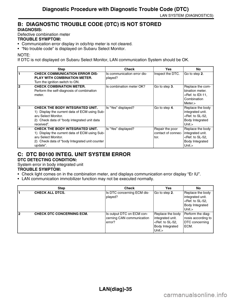
B: DIAGNOSTIC TROUBLE CODE (DTC) IS NOT STORED
DIAGNOSIS:
Defective combination meter
TROUBLE SYMPTOM:
•Communication error display in odo/trip meter is not cleared.
•“No trouble code” is displayed on Subaru Select Monitor.
NOTE:
If DTC is not displayed on Subaru Select Monitor, LAN communication System should be OK.
C: DTC B0100 INTEG. UNIT SYSTEM ERROR
DTC DETECTING CONDITION:
System error in body integrated unit
TROUBLE SYMPTOM:
•Check light comes on in the combination meter, and displays communication error display “Er IU”.
•LAN communication immobilizer function may not be executed normally.
Step Check Yes No
1CHECK COMMUNICATION ERROR DIS-
PLAY WITH COMBINATION METER.
Tu r n t h e i g n i t i o n s w i t c h t o O N .
Is communication error dis-
played?
Inspect the DTC. Go to step 2.
2CHECK COMBINATION METER.
Perfor m the self-diagnosis of combination
meter.
Is combination meter OK? Go to step 3.Replace the com-
bination meter.
Meter.>
3CHECK THE BODY INTEGRATED UNIT.
1) Display the current data of ECM using Sub-
aru Select Monitor.
2) Check data of “body integrated unit data
received”.
Is “Yes” displayed? Go to step 4.Replace the body
integrated unit.
Unit.>
4CHECK THE BODY INTEGRATED UNIT.
1) Display the current data of ECM using Sub-
aru Select Monitor.
2) Check data of “body Integrated unit counter
update”.
Is “Yes” displayed? Repair the poor
contact of connec-
tor.
Replace the body
integrated unit.
Unit.>
Step Check Yes No
1CHECK ALL DTCS.Is DTC concerning ECM dis-
played?
Go to step 2.Replace the body
integrated unit.
Unit.>
2CHECK DTC CONCERNING ECM.Is output DTC on ECM con-
cerning CAN communication
error?
Replace the body
integrated unit.
Unit.>
Per fo r m th e di ag -
nosis according to
DTC concerning
ECM.
Page 520 of 2453
LAN(diag)-64
Diagnostic Procedure with Diagnostic Trouble Code (DTC)
LAN SYSTEM (DIAGNOSTICS)
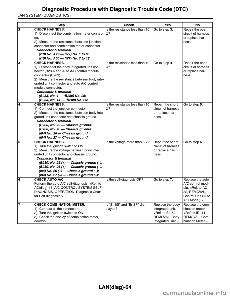
2CHECK HARNESS.
1) Disconnect the combination meter connec-
tor.
2) Measure the resistance between junction
connector and combination meter connector.
Connector & terminal
(i10) No. A29 — (i77) No. 1 to 6:
(i10) No. A30 — (i77) No. 7 to 12:
Is the resistance less than 10
Ω?
Go to step 3.Repair the open
circuit of harness
or replace har-
ness.
3CHECK HARNESS.
1) Disconnect the body integrated unit con-
nector (B280) and Auto A/C control module
connector (B283).
2) Measure the resistance between body inte-
grated unit connector and auto A/C control
module connector.
Connector & terminal
(B283) No. 1 — (B280) No. 26:
(B283) No. 14 — (B280) No. 25:
Is the resistance less than 10
Ω?
Go to step 4.Repair the open
circuit of harness
or replace har-
ness.
4CHECK HARNESS.
1) Connect the junction connector.
2) Measure the resistance between body inte-
grated unit connector and chassis ground.
Connector & terminal
(B280) No. 25 — Chassis ground:
(B280) No. 26 — Chassis ground:
(i84) No. 26 — Chassis ground:
(i84) No. 27 — Chassis ground:
Is the resistance less than 10
Ω?
Repair the short
circuit of harness
or replace har-
ness.
Go to step 5.
5CHECK HARNESS.
1) Turn the ignition switch to ON.
2) Measure the voltage between body inte-
grated unit connector and chassis ground.
Connector & terminal
(B280) No. 25 (+) — Chassis ground (–):
(B280) No. 26 (+) — Chassis ground (–):
(i84) No. 26 (+) — Chassis ground (–):
(i84) No. 27 (+) — Chassis ground (–):
Is the voltage more than 6 V? Repair the short
circuit of harness
or replace har-
ness.
Go to step 6.
6CHECK AUTO A/C.
Perfor m the auto A/C self-diagnosis.
DIAGNOSIS, OPERATION, Diagnostic Chart
for Self-diagnosis.>
Is the self-diagnosis OK? Go to step 7.Replace the auto
A/C control mod-
ule.
Control Unit (Auto
A/C Model).>
7CHECK COMBINATION METER.
1) Connect all the connectors.
2) Turn the ignition switch to ON.
3) Check the display of combination meter,
odo/trip.
Is “Er SS” and “Er SP” dis-
played?
Replace the body
integrated unit.
Integrated Unit.>
Replace the com-
bination meter.
bination Meter.>
Step Check Yes No
Page 522 of 2453
LAN(diag)-66
Diagnostic Procedure with Diagnostic Trouble Code (DTC)
LAN SYSTEM (DIAGNOSTICS)
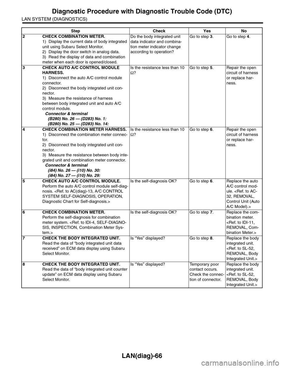
2CHECK COMBINATION METER.
1) Display the current data of body integrated
unit using Subaru Select Monitor.
2) Display the door switch in analog data.
3) Read the display of data and combination
meter when each door is opened/closed.
Do the body integrated unit
data indicator and combina-
tion meter indicator change
according to operation?
Go to step 3.Go to step 4.
3CHECK AUTO A/C CONTROL MODULE
HARNESS.
1) Disconnect the auto A/C control module
connector.
2) Disconnect the body integrated unit con-
nector.
3) Measure the resistance of harness
between body integrated unit and auto A/C
control module.
Connector & terminal
(B280) No. 26 — (D283) No. 1:
(B280) No. 25 — (D283) No. 14:
Is the resistance less than 10
Ω?
Go to step 5.Repair the open
circuit of harness
or replace har-
ness.
4CHECK COMBINATION METER HARNESS.
1) Disconnect the combination meter connec-
tor.
2) Disconnect the body integrated unit con-
nector.
3) Measure the resistance between body inte-
grated unit and combination meter connector.
Connector & terminal
(i84) No. 26 — (i10) No. 30:
(i84) No. 27 — (i10) No. 29:
Is the resistance less than 10
Ω?
Go to step 6.Repair the open
circuit of harness
or replace har-
ness.
5CHECK AUTO A/C CONTROL MODULE.
Perfor m the auto A/C control module self-diag-
nosis.
Diagnostic Chart for Self-diagnosis.>
Is the self-diagnosis OK? Go to step 6.Replace the auto
A/C control mod-
ule.
Control Unit (Auto
A/C Model).>
6CHECK COMBINATION METER.
Perfor m the self-diagnosis for combination
meter system.
tem.>
Is the self-diagnosis OK? Go to step 7.Replace the com-
bination meter.
bination Meter.>
7CHECK THE BODY INTEGRATED UNIT.
Read the data of “body integrated unit data
received” on ECM data display using Subaru
Select Monitor.
Is “Yes” displayed? Go to step 8.Replace the body
integrated unit.
Integrated Unit.>
8CHECK THE BODY INTEGRATED UNIT.
Read the data of “body integrated unit counter
update” on ECM data display using Subaru
Select Monitor.
Is “Yes” displayed? Temporary poor
contact occurs.
Check the connec-
tion of connector.
Replace the body
integrated unit.
Integrated Unit.>
Step Check Yes No
Page 524 of 2453
LAN(diag)-68
Diagnostic Procedure with Diagnostic Trouble Code (DTC)
LAN SYSTEM (DIAGNOSTICS)
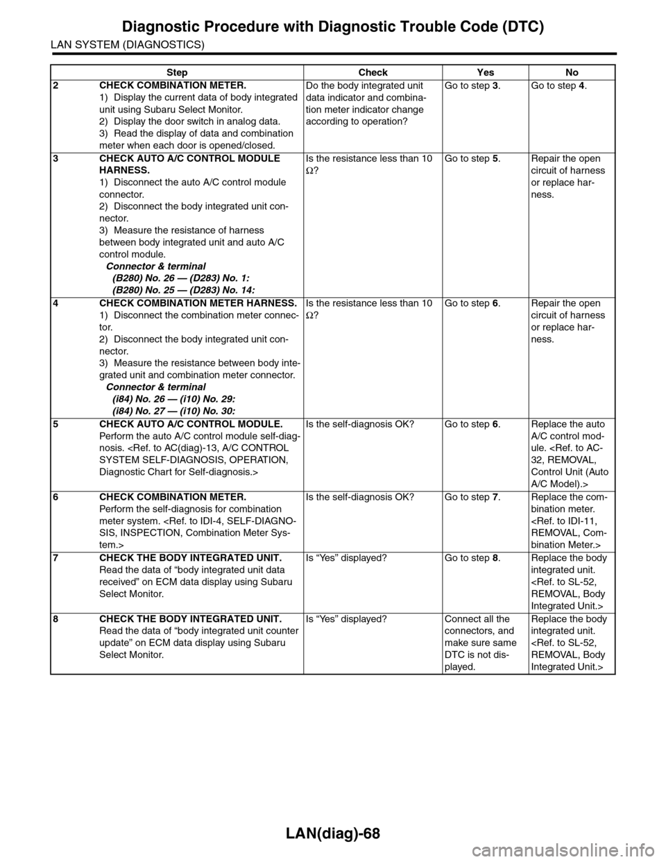
2CHECK COMBINATION METER.
1) Display the current data of body integrated
unit using Subaru Select Monitor.
2) Display the door switch in analog data.
3) Read the display of data and combination
meter when each door is opened/closed.
Do the body integrated unit
data indicator and combina-
tion meter indicator change
according to operation?
Go to step 3.Go to step 4.
3CHECK AUTO A/C CONTROL MODULE
HARNESS.
1) Disconnect the auto A/C control module
connector.
2) Disconnect the body integrated unit con-
nector.
3) Measure the resistance of harness
between body integrated unit and auto A/C
control module.
Connector & terminal
(B280) No. 26 — (D283) No. 1:
(B280) No. 25 — (D283) No. 14:
Is the resistance less than 10
Ω?
Go to step 5.Repair the open
circuit of harness
or replace har-
ness.
4CHECK COMBINATION METER HARNESS.
1) Disconnect the combination meter connec-
tor.
2) Disconnect the body integrated unit con-
nector.
3) Measure the resistance between body inte-
grated unit and combination meter connector.
Connector & terminal
(i84) No. 26 — (i10) No. 29:
(i84) No. 27 — (i10) No. 30:
Is the resistance less than 10
Ω?
Go to step 6.Repair the open
circuit of harness
or replace har-
ness.
5CHECK AUTO A/C CONTROL MODULE.
Perfor m the auto A/C control module self-diag-
nosis.
Diagnostic Chart for Self-diagnosis.>
Is the self-diagnosis OK? Go to step 6.Replace the auto
A/C control mod-
ule.
Control Unit (Auto
A/C Model).>
6CHECK COMBINATION METER.
Perfor m the self-diagnosis for combination
meter system.
tem.>
Is the self-diagnosis OK? Go to step 7.Replace the com-
bination meter.
bination Meter.>
7CHECK THE BODY INTEGRATED UNIT.
Read the data of “body integrated unit data
received” on ECM data display using Subaru
Select Monitor.
Is “Yes” displayed? Go to step 8.Replace the body
integrated unit.
Integrated Unit.>
8CHECK THE BODY INTEGRATED UNIT.
Read the data of “body integrated unit counter
update” on ECM data display using Subaru
Select Monitor.
Is “Yes” displayed? Connect all the
connectors, and
make sure same
DTC is not dis-
played.
Replace the body
integrated unit.
Integrated Unit.>
Step Check Yes No
Page 525 of 2453
LAN(diag)-69
Diagnostic Procedure with Diagnostic Trouble Code (DTC)
LAN SYSTEM (DIAGNOSTICS)
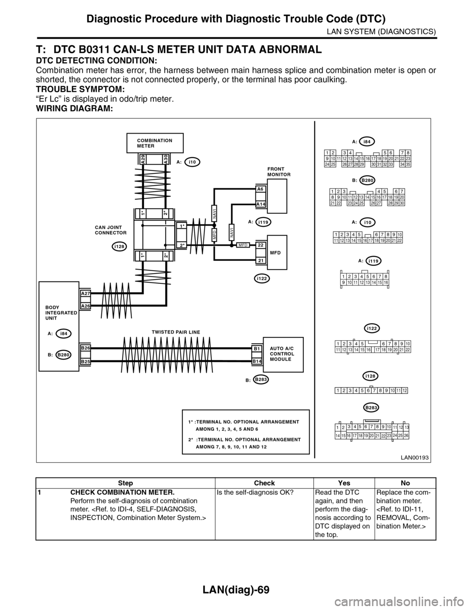
T: DTC B0311 CAN-LS METER UNIT DATA ABNORMAL
DTC DETECTING CONDITION:
Combination meter has error, the harness between main harness splice and combination meter is open or
shorted, the connector is not connected properly, or the terminal has poor caulking.
TROUBLE SYMPTOM:
“Er Lc” is displayed in odo/trip meter.
WIRING DIAGRAM:
i128
1*
2*1*
2*
CAN JOINTCONNECTOR
i10
B283
A29A30
A27
A26
B26
B25
A: i84
B: B280B1
B14
TWISTED PAIR LINE
5467821931022 231112131415242526 2716171828 29192021 30
B280
i84
1234567891011121314151617181920212223242526272829303132333435
2345 678912 13 14 15 16 17 18 19 20 21 2210111
B283
i10
COMBINATIONMETER
BODYINTEGRATEDUNIT
AUTO A/CCONTROLMODULE
123456789101112
LAN00193
A:
B:
2*
1*
A6
A14
FRONTMONITOR
21
22MFD
2* :TERMINAL NO. OPTIONAL ARRANGEMENT AMONG 7, 8, 9, 10, 11 AND 12
1* :TERMINAL NO. OPTIONAL ARRANGEMENT AMONG 1, 2, 3, 4, 5 AND 6
i119
i122
A:
A:
A:
i119A:
i122
i128B:
MFDNAVI
MFD
NAVI
9
19 20
105672143131211
14 15 16 17
8
18222125262423
12345678910 11 12 13 14 15 16
345 678919 20 2114 15 16 17 1812101211 13 22
Step Check Yes No
1CHECK COMBINATION METER.
Perfor m the self-diagnosis of combination
meter.
Is the self-diagnosis OK? Read the DTC
again, and then
perform the diag-
nosis according to
DTC displayed on
the top.
Replace the com-
bination meter.
bination Meter.>
Page 529 of 2453
LAN(diag)-73
Diagnostic Procedure with Diagnostic Trouble Code (DTC)
LAN SYSTEM (DIAGNOSTICS)
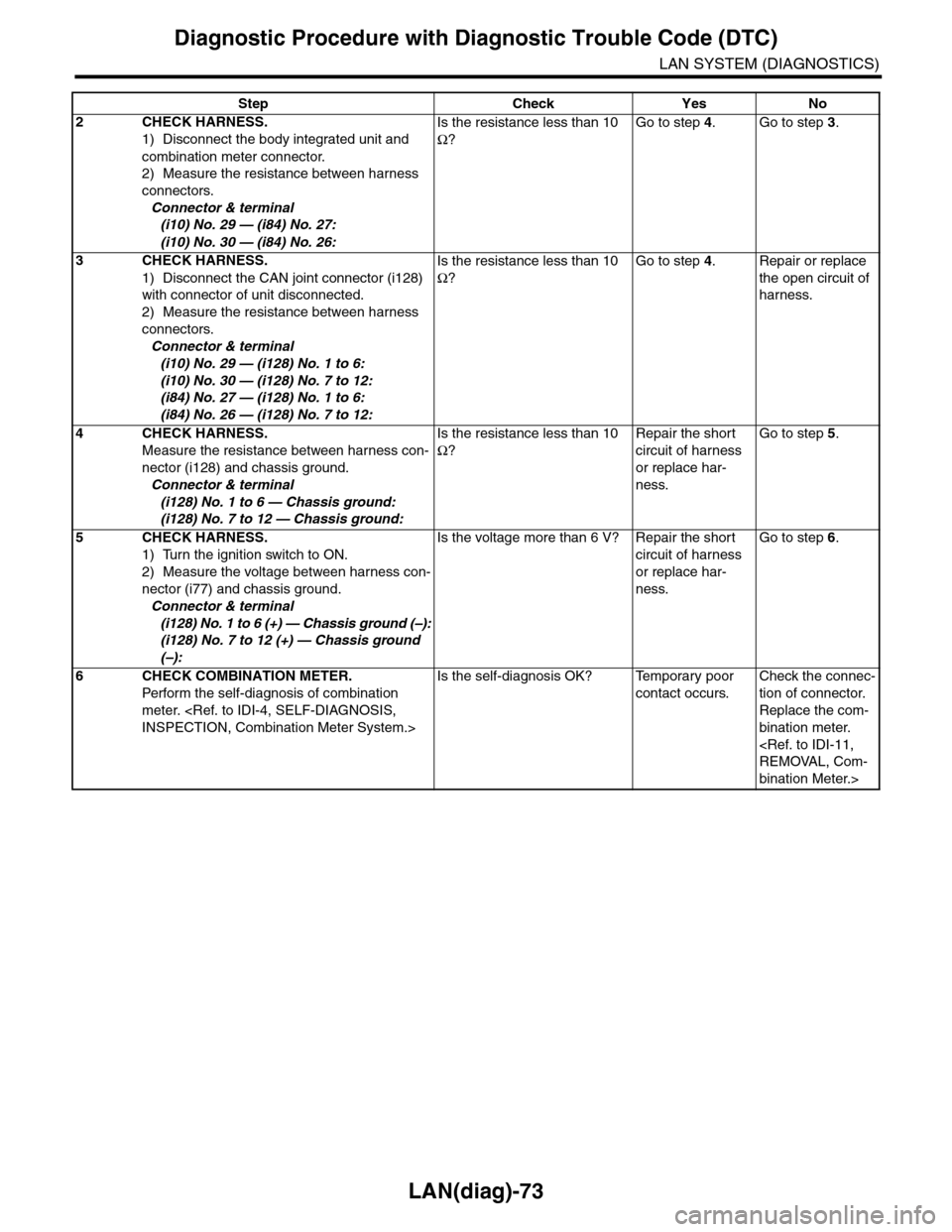
2CHECK HARNESS.
1) Disconnect the body integrated unit and
combination meter connector.
2) Measure the resistance between harness
connectors.
Connector & terminal
(i10) No. 29 — (i84) No. 27:
(i10) No. 30 — (i84) No. 26:
Is the resistance less than 10
Ω?
Go to step 4.Go to step 3.
3CHECK HARNESS.
1) Disconnect the CAN joint connector (i128)
with connector of unit disconnected.
2) Measure the resistance between harness
connectors.
Connector & terminal
(i10) No. 29 — (i128) No. 1 to 6:
(i10) No. 30 — (i128) No. 7 to 12:
(i84) No. 27 — (i128) No. 1 to 6:
(i84) No. 26 — (i128) No. 7 to 12:
Is the resistance less than 10
Ω?
Go to step 4.Repair or replace
the open circuit of
harness.
4CHECK HARNESS.
Measure the resistance between harness con-
nector (i128) and chassis ground.
Connector & terminal
(i128) No. 1 to 6 — Chassis ground:
(i128) No. 7 to 12 — Chassis ground:
Is the resistance less than 10
Ω?
Repair the short
circuit of harness
or replace har-
ness.
Go to step 5.
5CHECK HARNESS.
1) Turn the ignition switch to ON.
2) Measure the voltage between harness con-
nector (i77) and chassis ground.
Connector & terminal
(i128) No. 1 to 6 (+) — Chassis ground (–):
(i128) No. 7 to 12 (+) — Chassis ground
(–):
Is the voltage more than 6 V? Repair the short
circuit of harness
or replace har-
ness.
Go to step 6.
6CHECK COMBINATION METER.
Perfor m the self-diagnosis of combination
meter.
Is the self-diagnosis OK? Temporary poor
contact occurs.
Check the connec-
tion of connector.
Replace the com-
bination meter.
bination Meter.>
Step Check Yes No