window SUBARU TRIBECA 2009 1.G Service Workshop Manual
[x] Cancel search | Manufacturer: SUBARU, Model Year: 2009, Model line: TRIBECA, Model: SUBARU TRIBECA 2009 1.GPages: 2453, PDF Size: 46.32 MB
Page 233 of 2453
EB-14
Front Hood
EXTERIOR BODY PANELS
4) Remove the front fender.
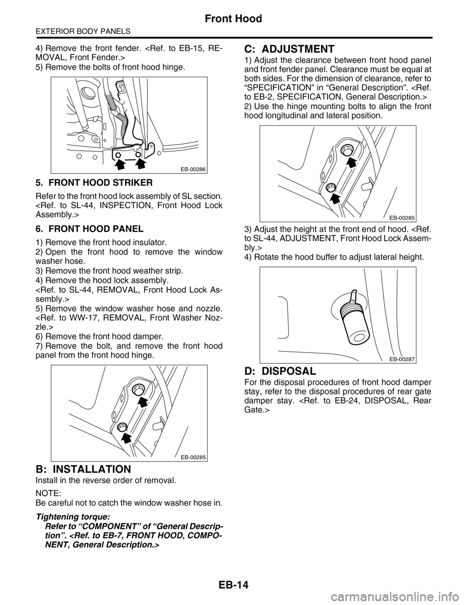
5) Remove the bolts of front hood hinge.
5. FRONT HOOD STRIKER
Refer to the front hood lock assembly of SL section.
6. FRONT HOOD PANEL
1) Remove the front hood insulator.
2) Open the front hood to remove the window
washer hose.
3) Remove the front hood weather strip.
4) Remove the hood lock assembly.
5) Remove the window washer hose and nozzle.
6) Remove the front hood damper.
7) Remove the bolt, and remove the front hood
panel from the front hood hinge.
B: INSTALLATION
Install in the reverse order of removal.
NOTE:
Be careful not to catch the window washer hose in.
Tightening torque:
Refer to “COMPONENT” of “General Descrip-
tion”.
C: ADJUSTMENT
1) Adjust the clearance between front hood panel
and front fender panel. Clearance must be equal at
both sides. For the dimension of clearance, refer to
“SPECIFICATION” in “General Description”.
2) Use the hinge mounting bolts to align the front
hood longitudinal and lateral position.
3) Adjust the height at the front end of hood.
bly.>
4) Rotate the hood buffer to adjust lateral height.
D: DISPOSAL
For the disposal procedures of front hood damper
stay, refer to the disposal procedures of rear gate
damper stay.
EB-00286
EB-00285
EB-00285
EB-00287
Page 252 of 2453
EI-10
General Description
EXTERIOR/INTERIOR TRIM
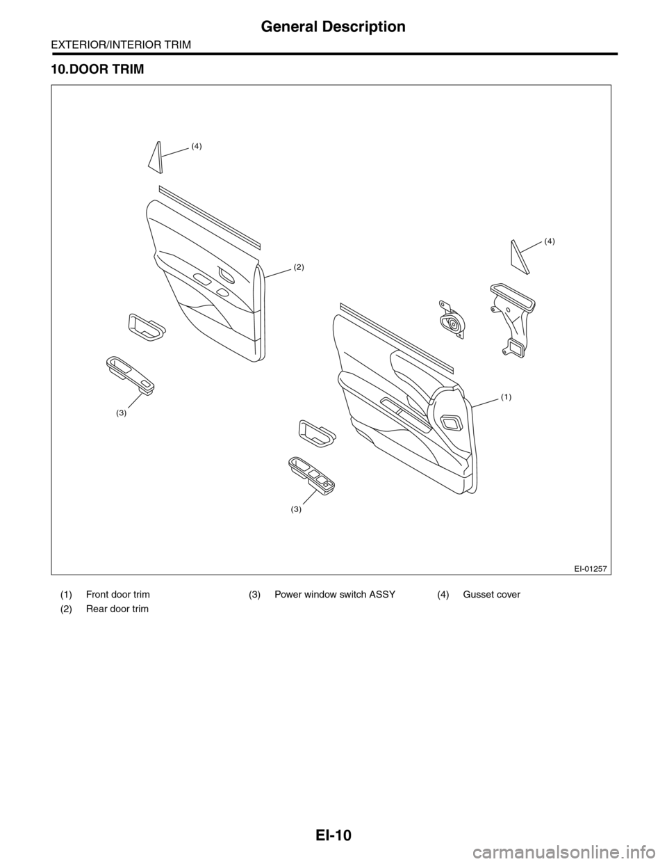
10.DOOR TRIM
(1) Front door trim (3) Power window switch ASSY (4) Gusset cover
(2) Rear door trim
EI-01257
(1)
(2)
(4)
(3)
(3)
(4)
Page 276 of 2453
EI-34
Roof Molding
EXTERIOR/INTERIOR TRIM
11.Roof Molding
A: REMOVAL
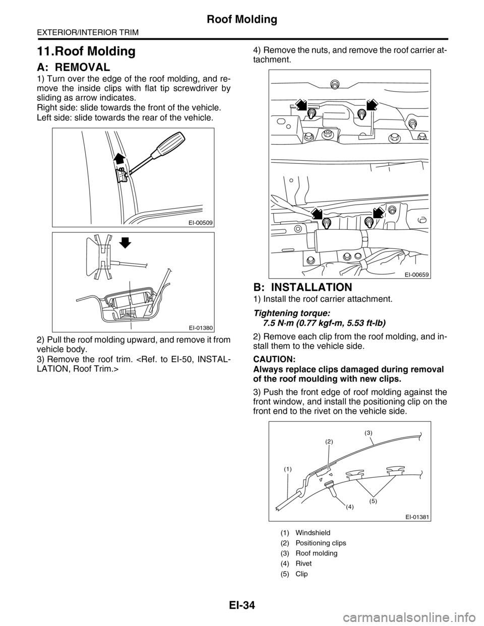
1) Turn over the edge of the roof molding, and re-
move the inside clips with flat tip screwdriver by
sliding as arrow indicates.
Right side: slide towards the front of the vehicle.
Left side: slide towards the rear of the vehicle.
2) Pull the roof molding upward, and remove it from
vehicle body.
3) Remove the roof trim.
4) Remove the nuts, and remove the roof carrier at-
tachment.
B: INSTALLATION
1) Install the roof carrier attachment.
Tightening torque:
7.5 N·m (0.77 kgf-m, 5.53 ft-lb)
2) Remove each clip from the roof molding, and in-
stall them to the vehicle side.
CAUTION:
Always replace clips damaged during removal
of the roof moulding with new clips.
3) Push the front edge of roof molding against the
front window, and install the positioning clip on the
front end to the rivet on the vehicle side.
EI-00509
EI-01380
(1) Windshield
(2) Positioning clips
(3) Roof molding
(4) Rivet
(5) Clip
EI-00659
EI-01381
(2)
(1)
(4)(5)
(3)
Page 277 of 2453
EI-35
Door Trim
EXTERIOR/INTERIOR TRIM
12.Door Trim
A: REMOVAL
1) Disconnect the ground cable from battery.
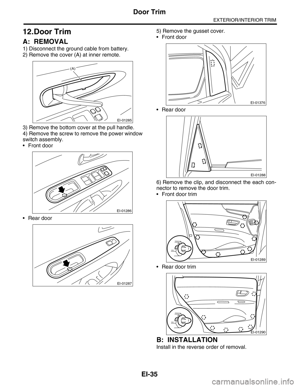
2) Remove the cover (A) at inner remote.
3) Remove the bottom cover at the pull handle.
4) Remove the screw to remove the power window
switch assembly.
•Front door
•Rear door
5) Remove the gusset cover.
•Front door
•Rear door
6) Remove the clip, and disconnect the each con-
nector to remove the door trim.
•Front door trim
•Rear door trim
B: INSTALLATION
Install in the reverse order of removal.
EI-01285
(A)
EI-01286
EI-01287
EI-01376
EI-01288
EI-01289
EI-01290
Page 297 of 2453
GW-2
General Description
GLASS/WINDOWS/MIRRORS
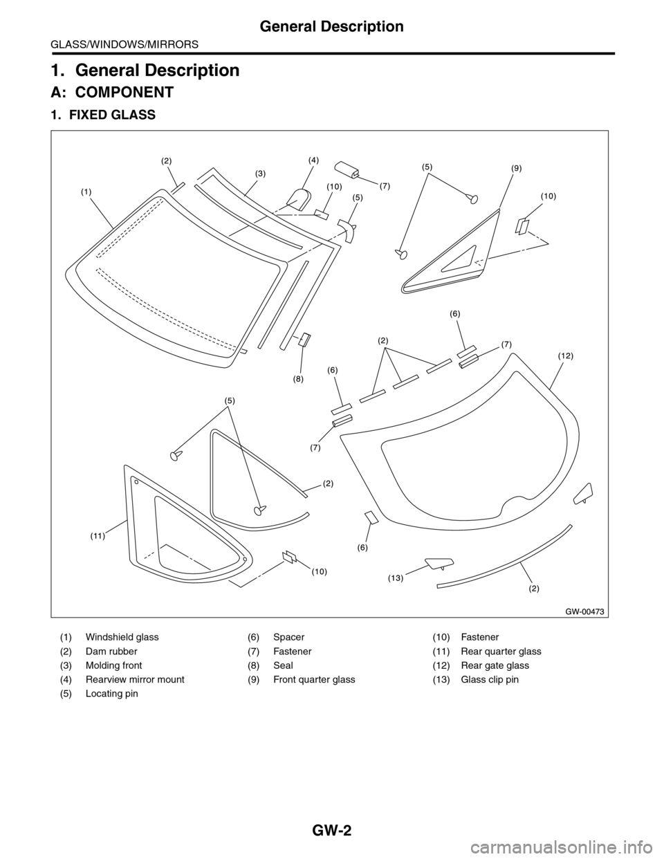
1. General Description
A: COMPONENT
1. FIXED GLASS
(1) Windshield glass (6) Spacer (10) Fastener
(2) Dam rubber (7) Fastener (11) Rear quarter glass
(3) Molding front (8) Seal (12) Rear gate glass
(4) Rearview mirror mount (9) Front quarter glass (13) Glass clip pin
(5) Locating pin
Page 298 of 2453
GW-3
General Description
GLASS/WINDOWS/MIRRORS
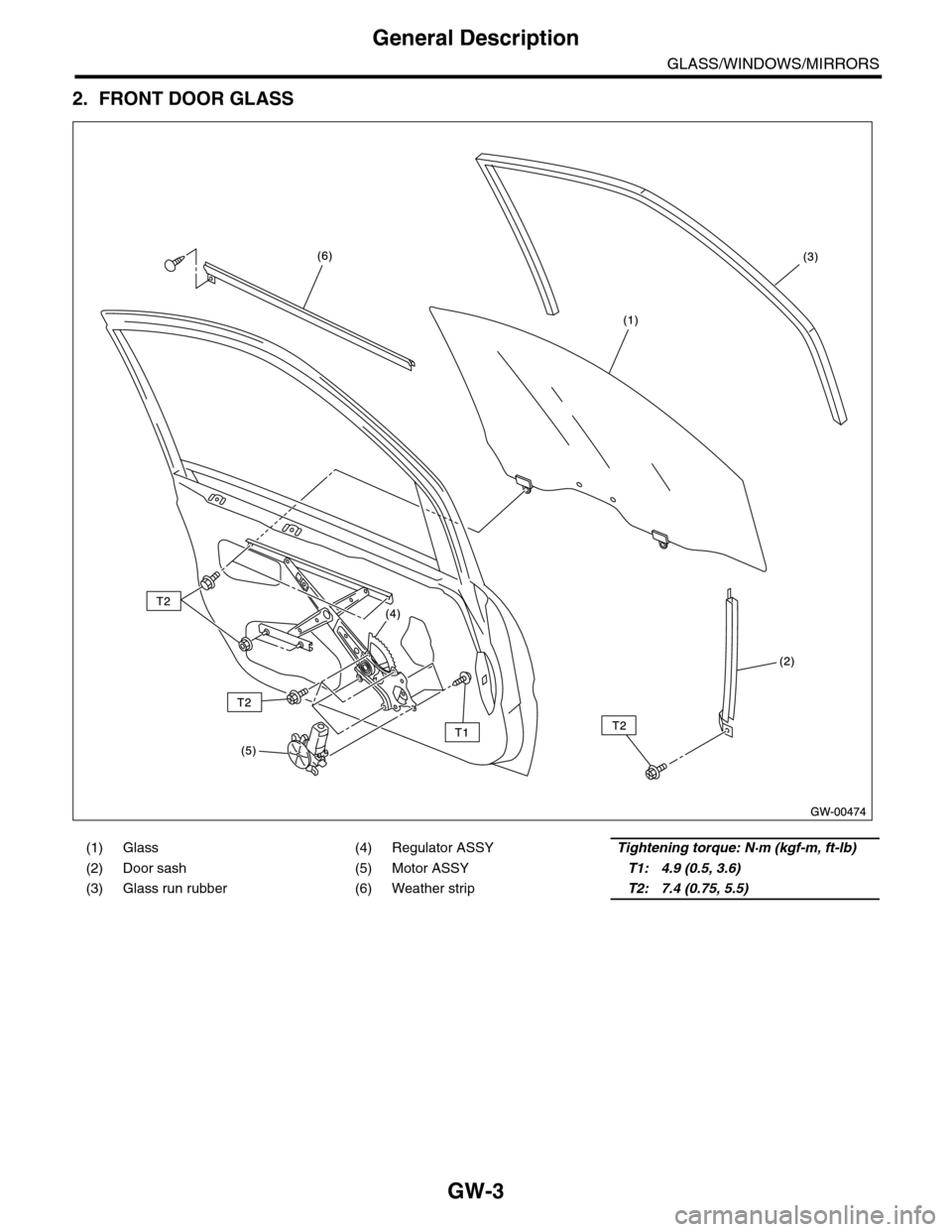
2. FRONT DOOR GLASS
(1) Glass (4) Regulator ASSYTightening torque: N·m (kgf-m, ft-lb)
(2) Door sash (5) Motor ASSYT1: 4.9 (0.5, 3.6)
(3) Glass run rubber (6) Weather stripT2: 7.4 (0.75, 5.5)
Page 299 of 2453

GW-4
General Description
GLASS/WINDOWS/MIRRORS
3. REAR DOOR GLASS
(1) Glass (4) Regulator ASSYTightening torque: N·m (kgf-m, ft-lb)
(2) Door sash (5) Motor ASSYT: 7.4 (0.75, 5.5)
(3) Glass run rubber (6) Weather strip
Page 300 of 2453
GW-5
General Description
GLASS/WINDOWS/MIRRORS
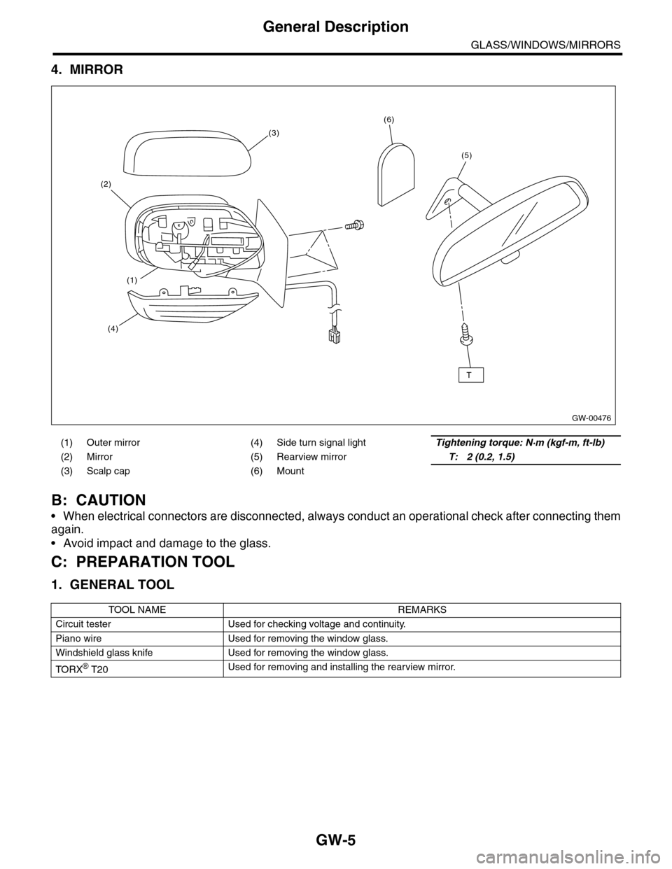
4. MIRROR
B: CAUTION
•When electrical connectors are disconnected, always conduct an operational check after connecting them
again.
•Avoid impact and damage to the glass.
C: PREPARATION TOOL
1. GENERAL TOOL
(1) Outer mirror (4) Side turn signal lightTightening torque: N·m (kgf-m, ft-lb)
(2) Mirror (5) Rearview mirrorT: 2 (0.2, 1.5)
(3) Scalp cap (6) Mount
TOOL NAME REMARKS
Circuit tester Used for checking voltage and continuity.
Piano wire Used for removing the window glass.
Windshield glass knife Used for removing the window glass.
TO RX® T20Used for removing and installing the rearview mirror.
GW-00476
(5)
(6)
(2)
(3)
(4)
(1)
T
Page 301 of 2453
GW-6
Power Window System
GLASS/WINDOWS/MIRRORS
2. Power Window System
A: WIRING DIAGRAM
B: INSPECTION
Symptom Repair order
All power windows do not operate.
1. Fuse (SBF-4)
2. Power window circuit breaker
3. Power window relay
4. Wiring Harness
5. Body integrated unit
Par ticular window does not operate.
1. Power window main switch
2. Power window sub switch
3. Power window motor
4. Wiring Harness
“Window Lock” does not operate. Power window main switch
Page 302 of 2453
GW-7
Power Window Control Switch
GLASS/WINDOWS/MIRRORS
3. Power Window Control
Switch
A: REMOVAL
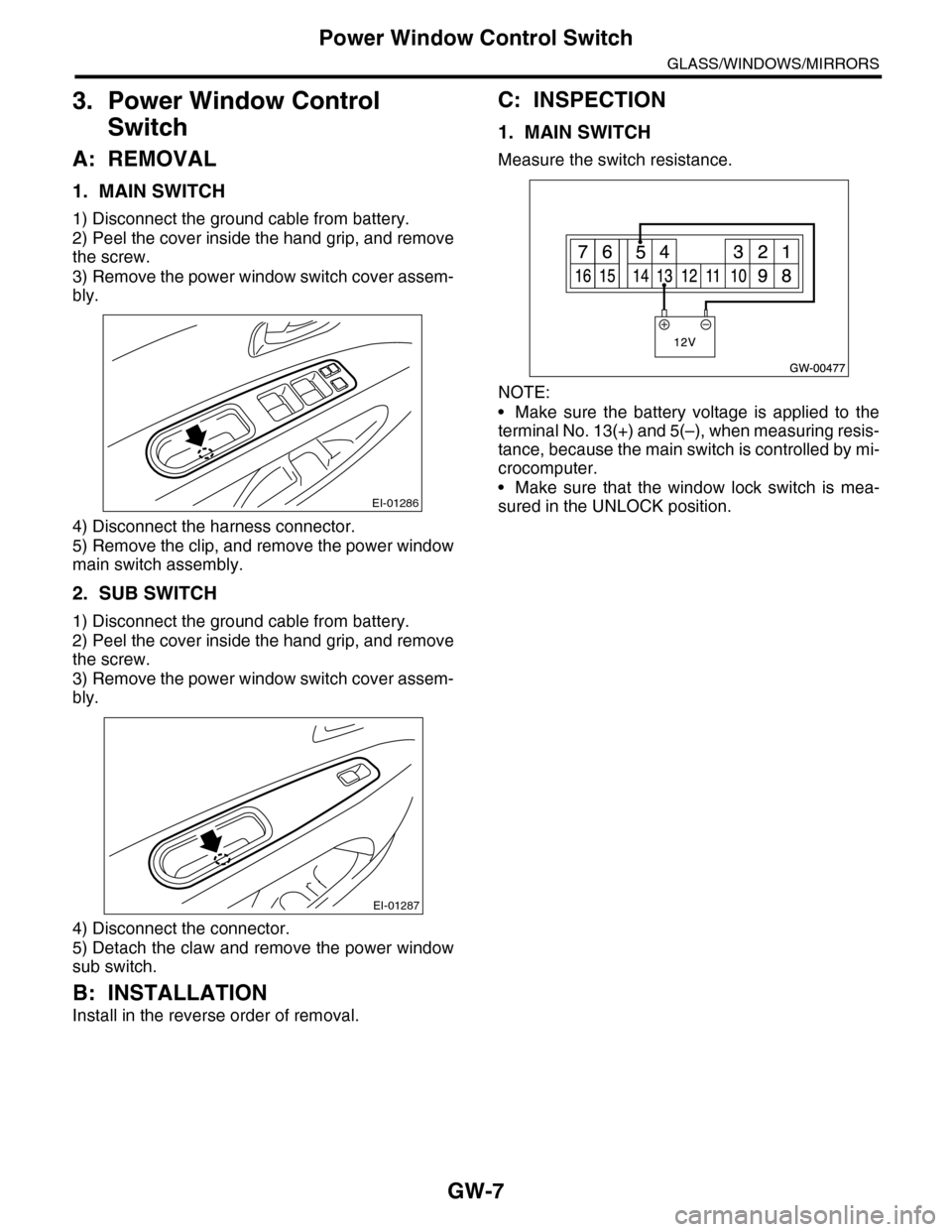
1. MAIN SWITCH
1) Disconnect the ground cable from battery.
2) Peel the cover inside the hand grip, and remove
the screw.
3) Remove the power window switch cover assem-
bly.
4) Disconnect the harness connector.
5) Remove the clip, and remove the power window
main switch assembly.
2. SUB SWITCH
1) Disconnect the ground cable from battery.
2) Peel the cover inside the hand grip, and remove
the screw.
3) Remove the power window switch cover assem-
bly.
4) Disconnect the connector.
5) Detach the claw and remove the power window
sub switch.
B: INSTALLATION
Install in the reverse order of removal.
C: INSPECTION
1. MAIN SWITCH
Measure the switch resistance.
NOTE:
•Make sure the battery voltage is applied to the
terminal No. 13(+) and 5(–), when measuring resis-
tance, because the main switch is controlled by mi-
crocomputer.
•Make sure that the window lock switch is mea-
sured in the UNLOCK position.EI-01286
EI-01287