ECU SUZUKI GRAND VITARA 1987 Service Owner's Manual
[x] Cancel search | Manufacturer: SUZUKI, Model Year: 1987, Model line: GRAND VITARA, Model: SUZUKI GRAND VITARA 1987Pages: 962, PDF Size: 27.87 MB
Page 108 of 962

-1. Key
‘32. Crankshaft pulley3. Pulley bolt
Fig. 3-6-52 Installing crankshaft pulley
2) Install alternator assembly.
Tighten alternator ass’y securing bolts (3pcs)
only to the extent to allow alternator to be
moved by hand. Don’t torque them tight.
NOTE:
Adjust water pump belt tension to specification
upon completion of installing engine ass’y to
body and then cooling fan and water pump
pulley. Make sure to refer to p. 1-5 of this
manual for adjusting procedure.
Distributor Case
1) Install distributor case O-ring to cylinder
head.
2) Install distributor case.
3) Tighten bolts to specified torque.
Tightening torque N.mkg-mlb-ft
forcasebolts8-120.8-1.26.0-8.5
Fig. 3-6-53
Fuel Pump
Install fuel pump rod, gasket and fuel pump to
cylinder head.
Apply engine oil to rod @ before installation.
Use new gasket.
Fig. 3-6-54 Fuel pump rod installation
case with about 3Occ (1.02/1.05 US/Imp
3-51
Page 110 of 962

3-7. ENGINE INSTALLATION
1) Lower engine with transmission into vehicle,
but do not remove lifting device.
2) Tighten engine mounting bracket bolts
(right and left) and transmission mounting
bolts to specification. Refer to p. 3-58.
3) Remove lifting device.
4) Reverse removal procedures for installation
of remainder.
5) Adjust accelerator cable play and clutch
cable play.
6) Connect vacuum hoses securely. Refer to
section 5 “EMISSION CONTROL SYSTEM”
for correct connection.
7) Connect wire harnesses and couplers secure-
IY.
8) Tighten bolts and nuts to specified torque.
For individual specification, refer to each
section.
9) Fill specified amount of specified trans-
mission oil and engine oil. For the detail,
refer to SECTION 1 PERIODIC MAINTE-
NANCE SERVICE of this manual.
10) After adjusting water pump belt tension to
specification, fill specified amount of engine
cooling water.
11) Before starting engine, check again to ensure
that all parts once disassembled or discon-
nected are back in place securely.
12)Start engine and check ignition timing. If
it is not to specified timing, adjust it, referr-
ing to SECTION 8 of this manual.
13) After engine is started, check for oil leak,
abnormal noise and other malcondition.
Also, check each part for operation.
3-8. ENGINE MAINTENANCE SERVICE
Fan Belt
Adjust belt tension as outlined in SECTION 6
ENGINE COOLING SYSTEM (p. 6-10).
Ignition Timing
Refer to IGNITION TIMING, Page 8-9.
Carburetor
fidjustments to be made are detailed in SEC-
TION 4 (p. 4-19).
Valve Lash (Clearance)
Valve lash specifications:
Valve lash refers to gap between rocker arm
adjusting screw and valve stem. Use a thickness
gauge to measure this gap @.
When coldWhen hot(Coolant tempe-(Coolant tempa-
Valve lashrature is 15 - 25%rature is 60 - 66’C
(gap A)or 69 - 77’F)or 140 - 154’F)
specif i-0.13 - 0.17 mm0.23 - 0.27 mmcationIntake(0.0051 - 0.0067 in) (0.009 - 0.011 in)
Exhaust0.16 -0.20 mm0.26 - 0.30 mm(0.0063 - 0.0079 in) (0.0102 - 0.0116 in)
Screw lock nut 15 - 19 N.m(1.5 - 1.9 kg-m, 11 .O - 13.5 lb-ft)
Adjusting screw
8
Valve stem
Fig. 3-8-l
Checking and adjusting procedures:
NOTE:
l Refer to Fig. 3-3-11 of SECTION 3 for
cylinder numbers (No. 1, No. 2, No. 3 and
No. 4) mentioned in this section.
l When adjustment becomes necessary in step
4), loosen adjusting screw lock nut and then
make adjustment by turning adjusting screw.
After adjustment, tighten lock nut to specifi-
ed torque while holding adjusting screw
stationary with straight headed screwdriver,
and then make sure again that gap @ is
within specification.
3-53
Page 128 of 962

0 Connect electric couplers securely.
l Connect accelerator cable to carburetor. With
the accelerator pedal released, adjust the cable
play to specification. This adjustment can be
made by turning the adjusting nut. After
adjustment, tighten the lock nut. Refer to
p. 4-19.
l Connect vacuum hoses securely.
l Refill cooling system.
l Connect negative cable at battery.
NOTE:
Upon completion of installation, be sure to
check each part for evidence of fuel leakage and
for proper operation. If defective, correct..
UNIT REPAIR OVERHAUL
This section outlines procedure to be used for
overhauling carburetor as removed from engine.
For removal and installation of carburetor from
and to engine, refer to the previous page.
NOTE:
l Be sure to replace gaskets as well as worn or
damaged parts.
l While disassembling and assembling carbure-
tor, use special care not to deform levers on
throttle valve shaft or cause damage to any
other parts.
l Don’t disassemble mixture control solenoid
valve and accelerator pump piston.
l Don’t remove idle and wide open micro
switches from the bracket where they are
installed.
Disassembly
1) Turn fast idle cam counterclockwise and
insert a pin avialable into holes on cam and
bracket to lock the cam.
Fig. 4- I- 19
1. Fast idle cam
2. Bracket3. Pin
4-13
Page 134 of 962
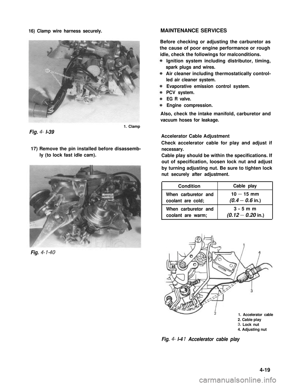
16) Clamp wire harness securely.MAINTENANCE SERVICES
Fig. 4- l-39
1. Clamp
17) Remove the pin installed before disassemb-
ly (to lock fast idle cam).
Fig. 4- l-40
Before checking or adjusting the carburetor as
the cause of poor engine performance or rough
idle, check the followings for malconditions.
Ignition system including distributor, timing,
spark plugs and wires.
Air cleaner including thermostatically control-
led air cleaner system.
Evaporative emission control system.
PCV system.
EG R valve.
Engine compression.
Also, check the intake manifold, carburetor and
vacuum hoses for leakage.
Accelerator Cable Adjustment
Check accelerator cable for play and adjust if
necessary.
Cable play should be within the specifications. If
out of specification, loosen lock nut and adjust
by turning adjusting nut. Be sure to tighten lock
nut securely after adjustment.
Condition
When carburetor and
coolant are cold;
When carburetor and
coolant are warm;
Cable play
10 - 15 mm
(0.4 - 0.6 in.)
3-5mm
(0.12 - 0.20 in.)
1. Accelerator cable
2. Cable play
3. Lock nut
4. Adjusting nut
Fig. 4- l-4 1 Accelerator cable play
4-19
Page 141 of 962

With vacuum pump gauge set at Black side of
VTV, when pump is operated, pointer moves
considerably but moves back to zero position as
soon as pump operation is stopped.
Brown side
(Actuator side) Black side
Fig. 4-l-60
1. VTV
2. Vacuum pump gauge
install VTV. Refer to Fig. 4-l -2 for installation.
[ VSV (Vacuum Switching Valve)]
1) Disconnect VSV vacuum hoses from 3 way
joint and secondary actuator and while
blowing either hose, check that air doesn’t
come out of the other hose.
2) Turn on ignition switch and depress accelera-
tor pedal fully. 5 or 6 seconds later, while
blowing either vacuum hose, check that air
comes out of the other hose.
J5
Fig. 4- l-61
1I
1. vsv4. WOTS
2. Ignition switch5. ECM
3. Battery6. Blow air
If check results in steps 1) and 2)are not satisfac-
tory, either replace VSV or check WOTS and its
circuit referring to SECTION5 “EMISSION
CONTROL SYSTEM”.
Idle Speed Adjustment
NOTE:
Before starting engine, place transmission gear
shift lever in “Neutral”, and set parking brake
and block drive wheels.
Before idle speed check and adjustment, make
sure of the following.
l Lead wires and hoses of engine emission
control systems are connected securely.
l Accelerator cable has some play, that is, it is
not tight.
l All vacuum hoses are connected securely.
l Fuel level should be within round mark at the
center of level gauge.
l Valve lash is checked and adjusted according
to the maintenance schedule.
l Air cleaner has been properly installed and is
in good condition.
l All accessories (wipers, heater, lights, etc) are
out of service.
l Ignition timing is within specification.
l Idle up actuator is not operating when engine
is running at idle speed.
NOTE:
In areas above 4,00Ofeet( 1,220m) elevation
(high altitude), idle up system will be normally
in operation. Do not attempt to adjust the idle
speed.
After above items are all confirmed, adjust idle
speed as follows.
1) Warm up engine to normal operating tempe-
rature.
2) Check to ensure that idle speed is within
750 - 850 r/min (rpm).
3) If idle speed is not within specified range,
adjust by turning idle speed adjusting screw.
If idle speed can not be adjusted to the speci-
fication by turning the adjusting screw, it can
be due to faulty return of throttle valve or
some other reason. Determine cause and
repair, and then adjust idle speed to specifica-
tion.
4-26
Page 145 of 962
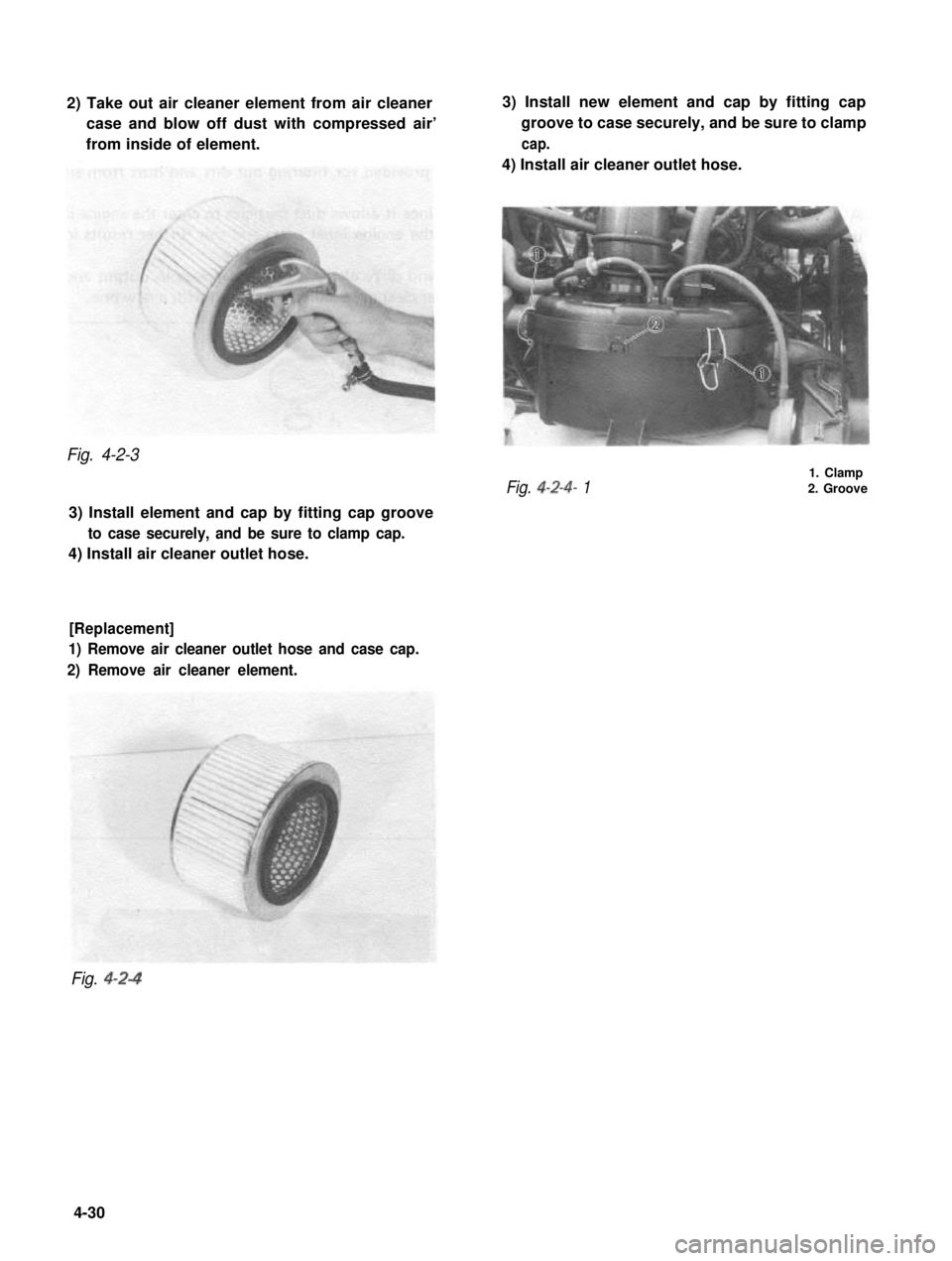
2) Take out air cleaner element from air cleaner
case and blow off dust with compressed air’
from inside of element.
3) Install new element and cap by fitting cap
groove to case securely, and be sure to clamp
cap.
4) Install air cleaner outlet hose.
Fig. 4-2-3
Fig. 4-2-4- 1
1. Clamp2. Groove
3) Install element and cap by fitting cap groove
to case securely, and be sure to clamp cap.
4) Install air cleaner outlet hose.
[Replacement]
1) Remove air cleaner outlet hose and case cap.
2) Remove air cleaner element.
Fig. 4-2-4
4-30
Page 148 of 962
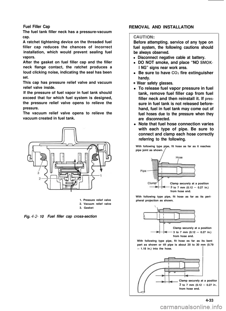
Fuel Filler Cap
The fuel tank filler neck has a pressure-vacuum
cap.
A ratchet tightening device on the threaded fuel
filler cap reduces the chances of incorrect
installation, which would prevent sealing fuel
vapors.
After the gasket on fuel filler cap and the filler
neck flange contact, the ratchet produces a
loud clicking noise, indicating the seal has been
set.
This cap has pressure relief valve and vacuum
relief valve inside.
If the pressure of fuel vapor in fuel tank should
exceed that for which fuel system is designed,
the pressure relief valve opens to relieve the
pressure.
The vacuum relief valve opens to relieve the
vacuum created in fuel tank.
1. Pressure relief valve2. Vacuum relief valve
3. Gasket
Fig. 4-2- 10Fuel filler cap cross-section
REMOVAL AND INSTALLATION
CALJTION:
Before attempting. service of any type on
fuel system, the following cautions should
be always observed.
l Disconnect negative cable at battery.
l DO NOT smoke, and place “NO SMOK-
I NG” signs near work area.
l Be sure to have COZ fire extinguisher
handy.
0 Wear safety glasses.
l To release fuel vapor pressure in fuel
tank, remove fuel filler cap from fuel
filler neck and then reinstall it. If prec
sure in fuel tank is not released before-
hand, fuel in fuel tank may come out of
fuel hoses due to the pressure when they
are disconnected.
l Note that fuel hose connection varies
with each type of pipe. Be sure to
connect and clamp each hose correctly
referring to the following.
With following type pipe, fit hose as far as it reachespipe joint as shown./
Clamp securely at a position
3 to 7 mm (0.12 - 0.27 in.)from hose end.
With following type pipe, fit hose as far as its peri-pheral projection as shown.
\
Clamp securely at a position
3 to 7 mm (0.12 - 0.27 in.)
from hose end.
With following type pipe, fit hose es far as its bentpart as shown or till pipe is about 20 to 30 mm (0.79
- 1.18 in.) into the hose.
Clamp securely at a positior
3 to 7 mm (0.12 - 0.27 in.:from hose end.
4-33
Page 150 of 962
![SUZUKI GRAND VITARA 1987 Service Owners Manual [Fuel tank purging procedure]
WARNING:
This purging procedure will NOT remove
all fuel vapor. Do not attempt any repair
on tank where heat or flame is required, as
an explosion resulting in personal i SUZUKI GRAND VITARA 1987 Service Owners Manual [Fuel tank purging procedure]
WARNING:
This purging procedure will NOT remove
all fuel vapor. Do not attempt any repair
on tank where heat or flame is required, as
an explosion resulting in personal i](/img/20/57437/w960_57437-149.png)
[Fuel tank purging procedure]
WARNING:
This purging procedure will NOT remove
all fuel vapor. Do not attempt any repair
on tank where heat or flame is required, as
an explosion resulting in personal injury
cou Id occur.J
The following procedure is used for purging the
fuel tank.
1) After removing fuel tank, remove all hoses,
fuel level gauge from fuel tank.
2) Drain all remaining fuel from tank.
3) Move tank to flushing area.
4) Fill tank with warm water or tap water, and
agitate vigorously and drain. Repeat this
washing until inside of tank is clean.
Replace tank if inside is rusty.
5) Completely flush out remaining water after
washing.
[ Installation]
Reverse removal procedure for installation using
care for the following.
Tightening torque30-45 Nm
for fuel tank(3.0- 4.5 kg-m)
drain plug(22.0 - 32.5 lb-ft)
Refer to Fig. 4-2-5 for piping and clamp posi-
tions.
l Make sure for correct hose-to-pipe connec-
tion.
l Clamp hoses securely.
l Upon completion of installation, start engine
and check hose joints for leaks.
MAINTENANCE SERVICES
Fuel Lines
Visually inspect fuel lines and connections for
evidence of fuel leakage, hose cracking, and
damage. Make sure all clamps are secure.
Repair leaky joints, if any.
Replace hoses that are suspected of being crack-
ed.
Fig. 4-2-14
Fuel Filler (tank) Cap
Visually inspect gasket of fuel filler cap.
If it is damaged or deteriorated, replace filler cap
with new one.
NOTE:
If cap requires replacement, only a cap with
the same features should be used. Failure to
use correct cap can result in a serious malfunc-
tion of the system.
Fig. 4-2-15
1. Fuel filler cap
2. Fuel filler capgasket
Fuel Filter
As said before, this filter does not permit dis-
assembly: it is to be replaced with a new one
periodically.
Replace fuel filter referring to previous item of
“Fuel Filter Removal and Installation”.
This servicing must be performed in a well
ventilated area and away from any open
flames (such as gas hot water heaters).
4-35
Page 151 of 962
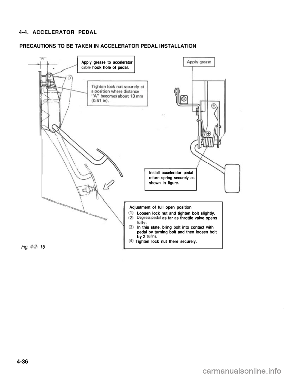
4-4. ACCELERATOR PEDAL
PRECAUTIONS TO BE TAKEN IN ACCELERATOR PEDAL INSTALLATION
“A’,
-w/i
Apply grease to accelerator
cable hook hole of pedal.
Install accelerator pedal
return spring securely as
shown in figure.
Fig. 4-2- 16
Adjustment of full open position
(1)Loosen lock nut and tighten bolt slightly.
(2)Depress Dedal as far as throttle valve opensf&
(3)In this state. bring bolt into contact with
pedal by turning bolt and then loosen boltby 2 tums.
(4) Tighten lock nut there securely.
4-36
Page 169 of 962
5-3. MAINTENANCE SERVICE
GENERAL
If the emission control hoses were disconnected
and any system component was removed for
service,be sure to reinstall the component
properly and route and connect hoses correctly
after service. Refer to Fig. 5-l-l for hose con-
nection.
PCV SYSTEM
Checking PCV System
NOTE:
If the engine is idling rough, this may be caused
by a stuck PCV valve, plugged hoses or vacuum
leakage of PCV line, therefore, never adjust the
carburetor idle without first checking the PCV
valve and hoses.
[ PCV hoses]
Check hoses for connection, leakage, clog, and
deterioration. Replace as necessary.
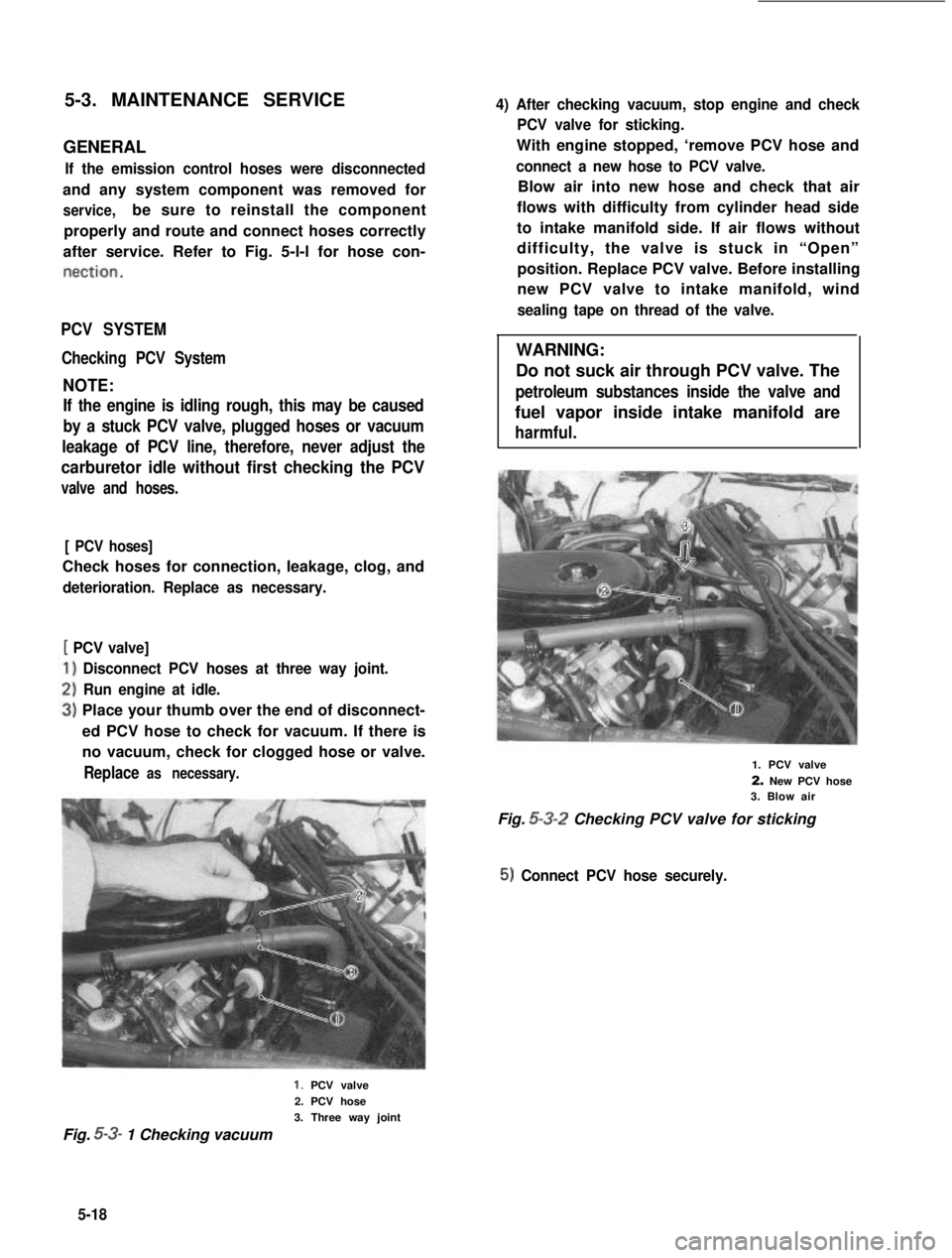
[ PCV valve]
Disconnect PCV hoses at three way joint.
Run engine at idle.
Place your thumb over the end of disconnect-
ed PCV hose to check for vacuum. If there is
no vacuum, check for clogged hose or valve.
Replace as necessary.
4) After checking vacuum, stop engine and check
PCV valve for sticking.
With engine stopped, ‘remove PCV hose and
connect a new hose to PCV valve.
Blow air into new hose and check that air
flows with difficulty from cylinder head side
to intake manifold side. If air flows without
difficulty, the valve is stuck in “Open”
position. Replace PCV valve. Before installing
new PCV valve to intake manifold, wind
sealing tape on thread of the valve.
WARNING:
Do not suck air through PCV valve. The
petroleum substances inside the valve and
fuel vapor inside intake manifold are
harmful.
1. PCV valve
2. New PCV hose3. Blow air
Fig. 5-3-2 Checking PCV valve for sticking
5) Connect PCV hose securely.
1. PCV valve
2. PCV hose
3. Three way joint
Fig. 5-3- 1 Checking vacuum
5-18