checking oil SUZUKI GRAND VITARA 1987 Service Repair Manual
[x] Cancel search | Manufacturer: SUZUKI, Model Year: 1987, Model line: GRAND VITARA, Model: SUZUKI GRAND VITARA 1987Pages: 962, PDF Size: 27.87 MB
Page 24 of 962
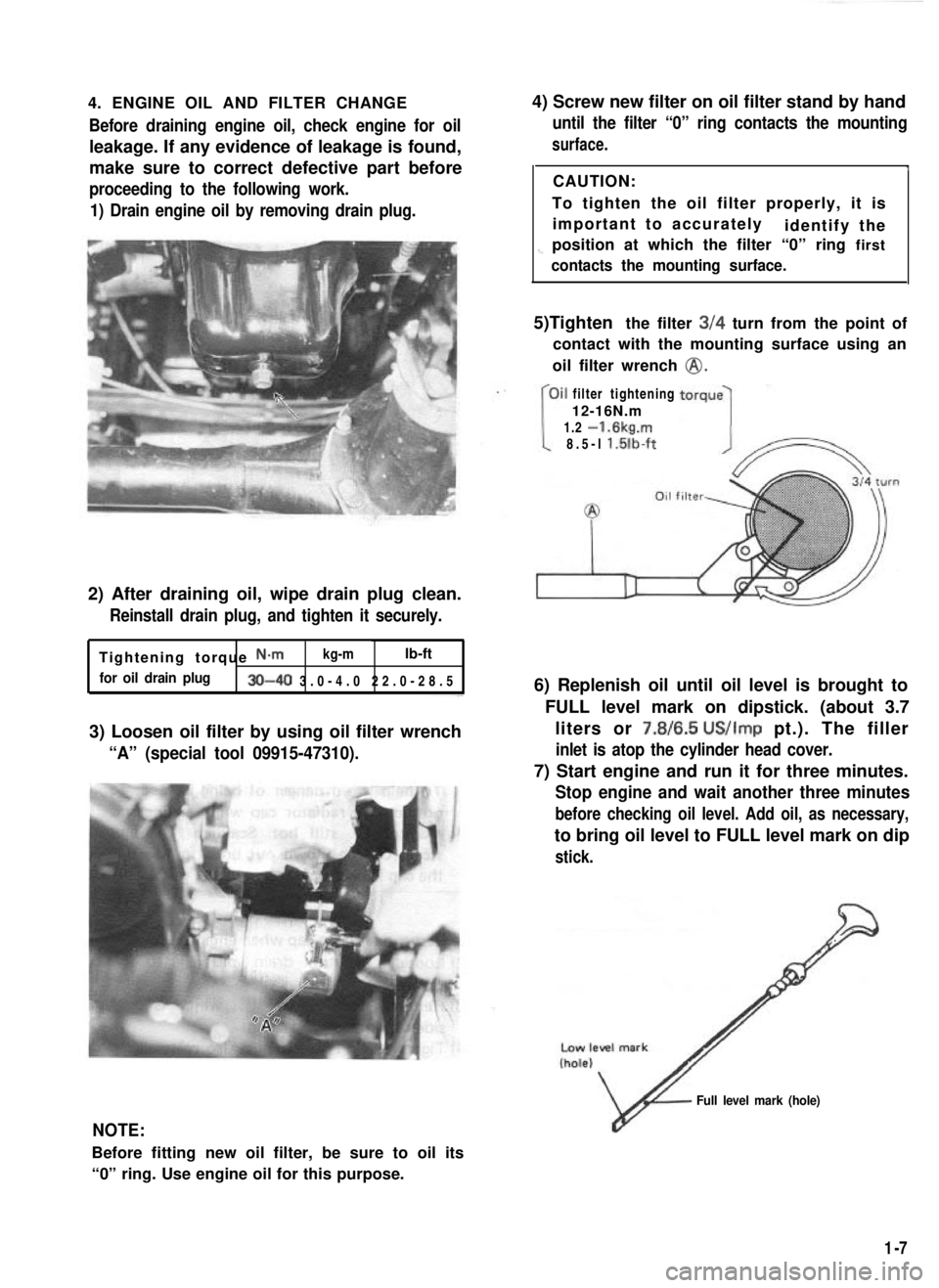
4. ENGINE OIL AND FILTER CHANGEBefore draining engine oil, check engine for oil
leakage. If any evidence of leakage is found,
make sure to correct defective part before
proceeding to the following work.
1) Drain engine oil by removing drain plug.
2) After draining oil, wipe drain plug clean.
Reinstall drain plug, and tighten it securely.
Tightening torque N-m kg-mlb-ft
for oil drain plug30-40 3.0-4.0 22.0-28.
5
3) Loosen oil filter by using oil filter wrench
“A” (special tool 09915-47310).
4) Screw new filter on oil filter stand by hand
until the filter “0” ring contacts the mounting
surface.
ICAUTION:
To tighten the oil filter properly, it is important to accurately identify the
1-position at which the filter “0” ring first
contacts the mounting surface.
5)Tighten the filter 3/4 turn from the point of
contact with the mounting surface using an
oil filter wrench
@.
filter tightening
12-16N.m
1.2
-1.6kg.m
8.5-l l.lilb-ft
6) Replenish oil until oil level is brought to
FULL level mark on dipstick. (about 3.7liters or 7.8/6.5
US/Imp pt.). The filler
inlet is atop the cylinder head cover.
7) Start engine and run it for three minutes.
Stop engine and wait another three minutes
before checking oil level. Add oil, as necessary,
to bring oil level to FULL level mark on dip
stick.
NOTE:
Before fitting new oil filter, be sure to oil its
“0” ring. Use engine oil for this purpose.
v
Full level mark (hole)
1-7
Page 29 of 962
NOTE:
When replacing plugs, make sure to use new
plugs of specified heat range and size.
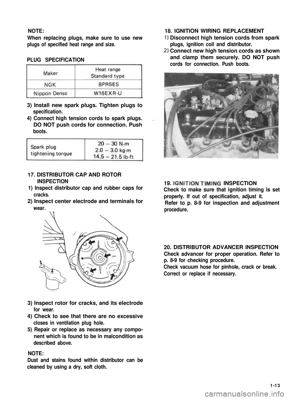
PLUG SPECIFICATION
~1
3) Install new spark plugs. Tighten plugs to
specification.
4) Connect high tension cords to spark plugs.
DO NOT push cords for connection. Push
boots.
17. DISTRIBUTOR CAP AND ROTOR
INSPECTION
1) Inspect distributor cap and rubber caps for
cracks.
2) Inspect center electrode and terminals for
wear.\‘(
3) Inspect rotor for cracks, and its electrode
for wear.
4) Check to see that there are no excessive
closes in ventilation plug hole.
5) Repair or replace as necessary any compo-
nent which is found to be in malcondition as
described above.
18. IGNITION WIRING REPLACEMENT
1) Disconnect high tension cords from spark
plugs, ignition coil and distributor.
2) Connect new high tension cords as shown
and clamp them securely. DO NOT push
cords for connection. Push boots.
19. IGNITION~TIMING INSPECTION
Check to make sure that ignition timing is set
properly. If out of specification, adjust it.
Refer to p. 8-9 for inspection and adjustment
procedure.
20. DISTRIBUTOR ADVANCER INSPECTION
Check advancer for proper operation. Refer to
p. 8-9 for checking procedure.
Check vacuum hose for pinhole, crack or break.
Correct or replace if necessary.
NOTE:
Dust and stains found within distributor can be
cleaned by using a dry, soft cloth.
1-13
Page 34 of 962
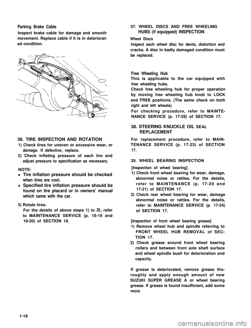
Parking Brake Cable
Inspect brake cable for damage and smooth
movement. Replace cable if it is in deteriorat-
ed condition.
36. TIRE INSPECTION AND ROTATION
1) Check tires for uneven or excessive wear, or
damage. If defective, replace.
2) Check inflating pressure of each tire and
adjust pressure to specification as necessary.
NOTE:
l Tire inflation pressure should be checked
when tires are cool.
l Specified tire inflation pressure should be
found on tire placard or in owners’ manual
which came with the car.
3) Rotate tires.
For the details of above steps 1) to 3), refer
to MAINTENANCE SERVICE (p. 18-19 and
18-20) of SECTION 18.
37. WHEEL DISCS AND FREE WHEELING
HUBS (if equipped) INSPECTION
Wheel Discs
Inspect each wheel disc for dents, distortion and
cracks. A disc in badly damaged condition must
be replaced.
Free Wheeling Hub
This is applicable to the car equipped with
free wheeling hubs.
Check free wheeling hub for proper operation
by moving free wheeling hub knob to LOCK
and FREE positions. (The same check on both
right and left wheels)
For checking procedure, refer to MAINTE-
NANCE SERVICE (p. 17-29) of SECTION 17.
38. STEERING KNUCKLE OIL SEAL
REPLACEMENT
For replacement procedure, refer to MAIN-
TENANCE SERVICE (p. 17-23) of SECTION
17.
39. WHEEL BEARING INSPECTION
[Inspection of wheel bearing]
1) Check front wheel bearing for wear, damage,
abnormal noise or rattles. For the details,
refer to MAINTENANCE (p. 17-20 and
17-21) of SECTION 17.
2) Check rear wheel bearing for wear, damage
abnormal noise or rattles. For the details,
refer to MAINTENANCE SERVICE (p. 17-24)
of SECTION 17.
[Inspection of front wheel bearing grease]
1) Remove wheel hub and spindle referring to
FRONT WHEEL HUB REMOVAL of SEC-
TION 17.
2) Check grease around front wheel bearing
rollars and between front axle shaft surface
and wheel spindle bush for deterioration and
capacity.
If grease is deteriorated, remove grease tho-
roughly and apply enough amount of new
SUZUKI SUPER GREASE A or wheel bearing
grease. If grease is found insufficient, add some
more.
1-18
Page 83 of 962
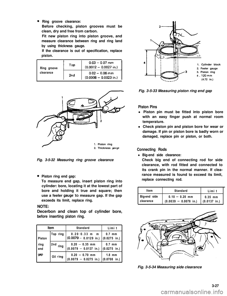
0Ring groove clearance:
Before checking, piston grooves must be
clean, dry and free from carbon.
Fit new piston ring into piston groove, and
measure clearance between ring and ring land
by using thickness gauge.
If the clearance is out of specification, replace
piston.
Ring groove
clearanceti1
1. Piston ring
2. Thickness geuge
Fig. 3-5-32 Measuring ring groove clearance
0Piston ring end gap:
To measure end gap, insert piston ring into
cylinder: bore, locating it at the lowest part of
bore and holding it true and square; then
use a feeler gauge’to measure gap. If the gap
exceeds its limit, replace ring.
NOTE:
Decerbon and clean top of cylinder bore,
before inserting piston ring.
ItemStandardLimit
Top ring0.20 0.33 mm-0.7 mm
Piston(0.0079 - 0.0129in.)(0.0275 in.)
ring2ndring0.20 - 0.35 mm0.7 mm
end(0.0079 - 0.0137 in.)(0.0275 in.)
QaPOil riilg0.20 - 0.70 mm1.8 mm
(0.0079 - 0.0275 in.)(0.0708 in.)
1. Cylinder block
2. Feeler gauge3. Piston ring4. 12Omm(4.72 in.)
Fig. 3-5-33 Measuring piston ring end gap
Piston Pins
l Piston pin must be fitted into piston bore
with an easy finger push at normal room
temperature.
l Check piston pin and piston bore for wear or
damage. If pin or piston bore is badly worn or
damaged, replace pin or piston, or both.
Connecting Rods
l Big-end side clearance:
Check big end of connecting rod for side
clearance, with rod fitted and connected to
its crank pin in the normal manner. If clea-
rance measured is found to exceed its limit,
replace connecting rod.
Item
Big-end side
clearance
StandardLimit
0.10 - 0.20 mm0.35 mm
(0.0039 - 0.0078 in.)(0.0137 in.)
Fig. 3-5-34 Measuring side clearance
3-27
Page 84 of 962
l Connecting rod alignment:
Mount connecting rod on aligner to check
it for bow and twist and, if either limit is
exceeded, replace it.
Limit on bow0.05 mm (0.0020 in.)
ILimit on twist) 0.10 mm (0.0039 in.) 1
Crank Pin and Connecting Rod Bearings
l Inspect crank pin for uneven wear or damage.
Measure crank pin for out-of-round or taper
with a micrometer. If crank pin is damaged,
or out-of-round or taper is out of limit,
replace crankshaft or regrind crank pin to
undersize and use undersize bearing.
I
Connecting
rod bearing sizeCrank pin diameterI
IStandard41.982 - 42.000 mm
(1.6529 - 1.6535 in.)I
0.25 mm (0.0098 in.)41.732 - 41.750 mm
undersize(1.6430 - 1.6437 in.)
Out-of-round and
taper limit0.01 mm (0.0004 in.)
l Rod bearing:
Inspect bearing shells for signs of fusion,
pitting, burn or flaking and observe contact
pattern. Bearing shells found in defective
condition must be replaced.
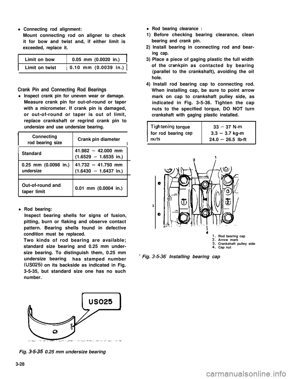
Two kinds of rod bearing are available;
standard size bearing and 0.25 mm under-
size bearing. To distinguish them, 0.25 mm
undersize bearinghas stamped number
(USO25) on its backside as indicated in Fig.
3-5-35, but standard size one has no such
number.
l Rod bearing clearance :
1) Before checking bearing clearance, clean
bearing and crank pin.
2) Install bearing in connecting rod and bear-
ing cap.
3) Place a piece of gaging plastic the full width
of the crankpin as contacted by bearing
(parallel to the crankshaft), avoiding the oil
hole.
4) Install rod bearing cap to connecting rod.
When installing cap, be sure to point arrow
mark on cap to crankshaft pulley side, as
indicated in Fig. 3-5-36. Tighten the cap
nuts to the specified torque, DO NOT turn
crankshaft with gaging plastic installed.
torque33-37 N-m
forrodbearingcap3.3-3.7 kg-m
24.0-26.5 lb-ft
e
3
0
.
’ Fig. 3-5-36 Installing bearing cap
Rod bearing capArrow markCrankshaft pulley sideCap nut
Fig. 3-5-35 0.25 mm undersize bearing
3-28
Page 87 of 962

Crankshaft Main (Journal) Bearings
General informations:
l Service main bearings are available in standard-
size and 0.25 mm (0.0098 in) undersize, and
each of them has 5 kinds of bearings differ-
ing in tolerance.
l The upper half of bearing has oil groove as
indicated in Fig. 3~5-42. Install this half with
oil groove to cylinder block.
Fig. 3-5-40 Measuring thrust play of crankshaft
l Out-of-round and taper (uneven wear):
An unevenly worn crankshaft journal shows
up as a difference in diameter at a cross
section or along its length (or both). This
difference, if any, is to be determined from
micrometer readings.
If any of journals is badly damaged or if the
amount of uneven wear in the sense explained
above exceeds its limit, regrind or replace the
crankshaft.
I
Limit on out-of-round
and taper0.01 mm (0.0004 in.)
Fig. 3-5-4 1 Checking uneven wear
1. Cylinder block2. Upper half of bearing
3. Oil groove
Fig. 3-5-42 Upper half of bearing installation
l On each main bearing cap, arrow mark and
number are embossed as indicated in Fig.
3-5-43.
When installing each bearing cap to cylinder
block, point arrow mark toward crankshaft
pulley side and install each cap from crank-
shaft pulley side to flywheel side in ascending
order of numbers @,a, 0, @ and 0. Tigh-
ten cap bolts to specified torque.
3
2. Flywheel side
Fig. 3-5-43 Bearing caps ins talla tion
3-30
Page 110 of 962

3-7. ENGINE INSTALLATION
1) Lower engine with transmission into vehicle,
but do not remove lifting device.
2) Tighten engine mounting bracket bolts
(right and left) and transmission mounting
bolts to specification. Refer to p. 3-58.
3) Remove lifting device.
4) Reverse removal procedures for installation
of remainder.
5) Adjust accelerator cable play and clutch
cable play.
6) Connect vacuum hoses securely. Refer to
section 5 “EMISSION CONTROL SYSTEM”
for correct connection.
7) Connect wire harnesses and couplers secure-
IY.
8) Tighten bolts and nuts to specified torque.
For individual specification, refer to each
section.
9) Fill specified amount of specified trans-
mission oil and engine oil. For the detail,
refer to SECTION 1 PERIODIC MAINTE-
NANCE SERVICE of this manual.
10) After adjusting water pump belt tension to
specification, fill specified amount of engine
cooling water.
11) Before starting engine, check again to ensure
that all parts once disassembled or discon-
nected are back in place securely.
12)Start engine and check ignition timing. If
it is not to specified timing, adjust it, referr-
ing to SECTION 8 of this manual.
13) After engine is started, check for oil leak,
abnormal noise and other malcondition.
Also, check each part for operation.
3-8. ENGINE MAINTENANCE SERVICE
Fan Belt
Adjust belt tension as outlined in SECTION 6
ENGINE COOLING SYSTEM (p. 6-10).
Ignition Timing
Refer to IGNITION TIMING, Page 8-9.
Carburetor
fidjustments to be made are detailed in SEC-
TION 4 (p. 4-19).
Valve Lash (Clearance)
Valve lash specifications:
Valve lash refers to gap between rocker arm
adjusting screw and valve stem. Use a thickness
gauge to measure this gap @.
When coldWhen hot(Coolant tempe-(Coolant tempa-
Valve lashrature is 15 - 25%rature is 60 - 66’C
(gap A)or 69 - 77’F)or 140 - 154’F)
specif i-0.13 - 0.17 mm0.23 - 0.27 mmcationIntake(0.0051 - 0.0067 in) (0.009 - 0.011 in)
Exhaust0.16 -0.20 mm0.26 - 0.30 mm(0.0063 - 0.0079 in) (0.0102 - 0.0116 in)
Screw lock nut 15 - 19 N.m(1.5 - 1.9 kg-m, 11 .O - 13.5 lb-ft)
Adjusting screw
8
Valve stem
Fig. 3-8-l
Checking and adjusting procedures:
NOTE:
l Refer to Fig. 3-3-11 of SECTION 3 for
cylinder numbers (No. 1, No. 2, No. 3 and
No. 4) mentioned in this section.
l When adjustment becomes necessary in step
4), loosen adjusting screw lock nut and then
make adjustment by turning adjusting screw.
After adjustment, tighten lock nut to specifi-
ed torque while holding adjusting screw
stationary with straight headed screwdriver,
and then make sure again that gap @ is
within specification.
3-53
Page 111 of 962
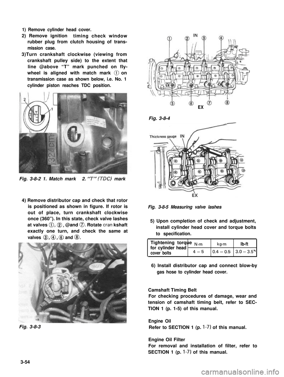
1) Remove cylinder head cover.
2) Remove ignitiontiming check window
rubber plug from clutch housing of trans-
mission case.
3)Turn crankshaft clockwise (viewing from
crankshaft pulley side) to the extent that
line @above “T” mark punched on fly-
wheel is aligned with match mark @ on
transmission case as shown below, i.e. No. 1
cylinder piston reaches TDC position.
Fig. 3-8-2 1. Match mark2. ‘7” (TDC) mark
4) Remove distributor cap and check that rotor
is positioned as shown in figure. If rotor is
out of place, turn crankshaft clockwise
once (360”). In this state, check valve lashes
at valves @,@I, @and 0. Rotate cran kshaft
exactly one turn, and check the same at
valves 8, @, @ and @I.
Fig. 3-8-3
EX
Fig. 3-8-4-
Fig. 3-8-5 Measuring valve lashes
5) Upon completion of check and adjustment,
install cylinder head cover and torque bolts
to specification.
Tightening torque N.,.,.,
for cylinder head Ib-mlb-ft
cover bolts4-50.4 - 0.53.0 - 3.5*
6) Install distributor cap and connect blow-by
gas hose to cylinder head cover.
Camshaft Timing Belt
For checking procedures of damage, wear and
tension of camshaft timing belt, refer to SEC-
TION 1 (p. 1-5) of this manual.
Engine Oil
Refer to SECTION 1 (p. I-7) of this manual.
Engine Oil Filter
For removal and installation of filter, refer to
SECTION 1 (p. I-7) of this manual.
3-54
Page 112 of 962
Engine Coolant
This subject is covered in SECTION 6 ENGINE
COOLING SYSTEM.
Exhaust Line and Muffler
Inspect each exhaust line connection for tight-
ness, and examine muffler and other parts for
evidence of breakage and leakage of gases.
Repair or replace defective parts, if any.
Compression Pressure Measurement
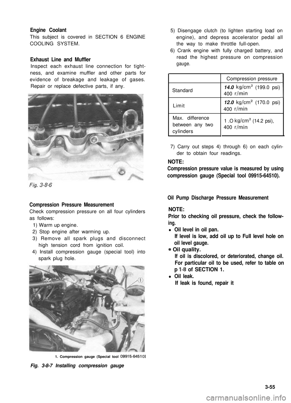
Check compression pressure on all four cylinders
as follows:
1) Warm up engine.
2) Stop engine after warming up.
3) Remove all spark plugs and disconnect
high tension cord from ignition coil.
4) Install compression gauge (special tool) into
spark plug hole.
5) Disengage clutch (to lighten starting load on
engine), and depress accelerator pedal all
the way to make throttle full-open.
6) Crank engine with fully charged battery, and
read the highest pressure on compression
gauge.
Standard
Limit
Max. difference
between any two
cylinders
Compression pressure
14.0 kg/cm2 (199.0 psi)
400 r/min
12.0 kg/cm2 (170.0 psi)
400 r/min
1 .O kg/cm2 (14.2 psi),
400 r/min
3
7) Carry out steps 4) through 6) on each cylin-
der to obtain four readings.
NOTE:
Compression pressure value is measured by using
compression gauge (Special tool 09915-64510).
Oil Pump Discharge Pressure Measurement
NOTE:
Prior to checking oil pressure, check the follow-
ing.
l Oil level in oil pan.
If level is low, add oil up to Full level hole on
oil level gauge.
0 Oil quality.
If oil is discolored, or deteriorated, change oil.
For particular oil to be used, refer to table on
p l-8 of SECTION 1.
l Oil leak.
If leak is found, repair it
1. Compression gauge (Special tool 09915-64510)
Fig. 3-8-7 Installing compression gauge
3-55
Page 113 of 962
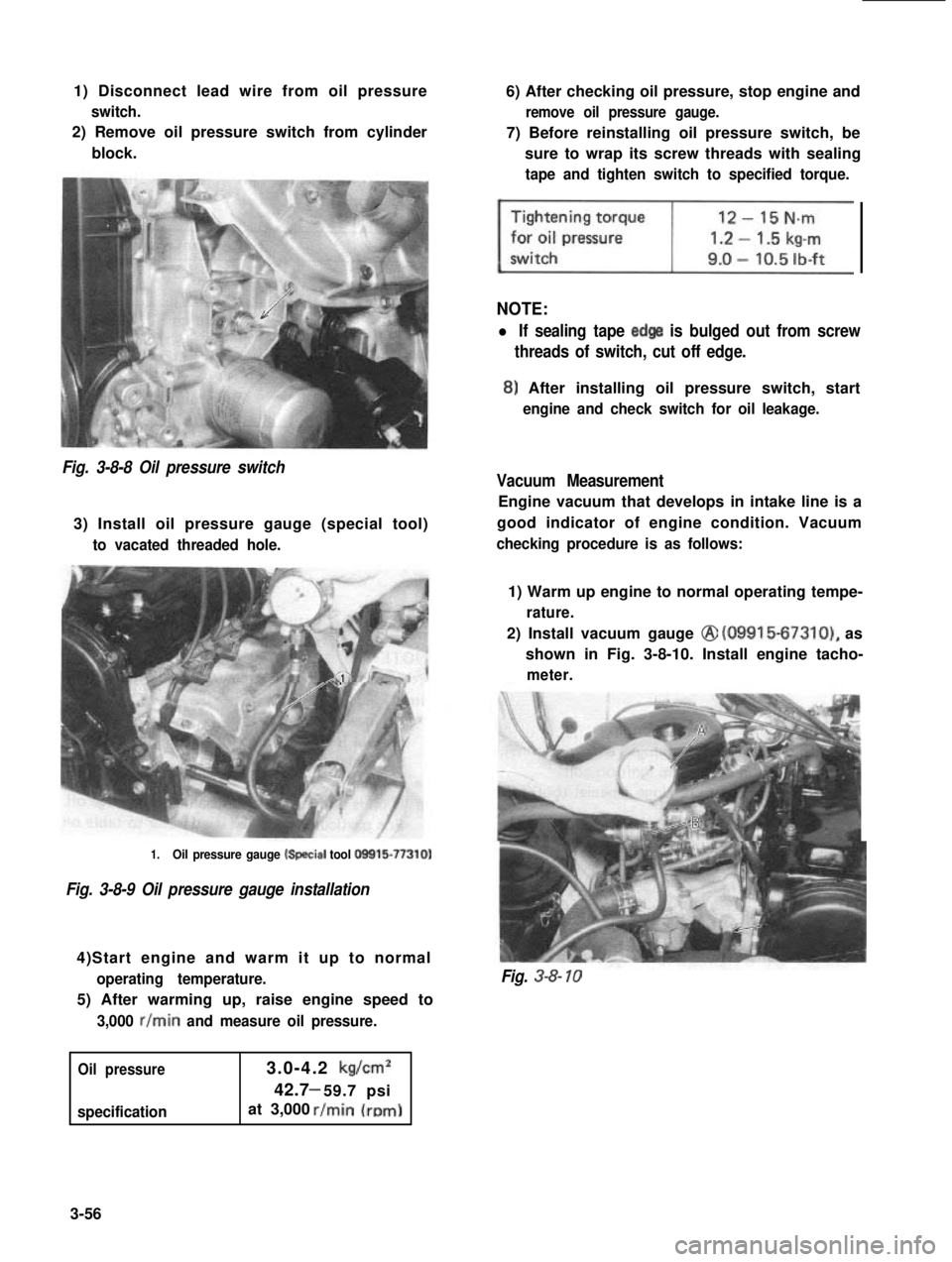
1) Disconnect lead wire from oil pressure
switch.
2) Remove oil pressure switch from cylinder
block.
6) After checking oil pressure, stop engine and
remove oil pressure gauge.
7) Before reinstalling oil pressure switch, be
sure to wrap its screw threads with sealing
tape and tighten switch to specified torque.
NOTE:
l If sealing tape edge is bulged out from screw
threads of switch, cut off edge.
8) After installing oil pressure switch, start
engine and check switch for oil leakage.
Fig. 3-8-8 Oil pressure switch
3) Install oil pressure gauge (special tool)
to vacated threaded hole.
Vacuum Measurement
Engine vacuum that develops in intake line is a
good indicator of engine condition. Vacuum
checking procedure is as follows:
1.Oil pressure gauge k+ecial tool O!Xil5-77310)
Fig. 3-8-9 Oil pressure gauge installation
4)Start engine and warm it up to normal
operating temperature.
5) After warming up, raise engine speed to
3,000 r/min and measure oil pressure.
Oil pressure
specification
3.0-4.2 kg/cm2
42.7 59.7 psi-
at 3,000
1) Warm up engine to normal operating tempe-
rature.
2) Install vacuum gauge @ (09915-67310), as
shown in Fig. 3-8-10. Install engine tacho-
meter.
Fig. 3-8- 10
3-56