checking oil SUZUKI GRAND VITARA 1987 Service User Guide
[x] Cancel search | Manufacturer: SUZUKI, Model Year: 1987, Model line: GRAND VITARA, Model: SUZUKI GRAND VITARA 1987Pages: 962, PDF Size: 27.87 MB
Page 114 of 962

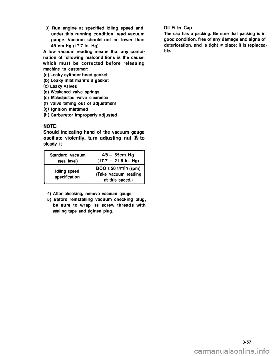
3) Run engine at specified idling speed and,
under this running condition, read vacuum
gauge. Vacuum should not be lower than
45 cm Hg (17.7 in. Hg).
A low vacuum reading means that any combi-
nation of following malconditions is the cause,
which must be corrected before releasing
machine to customer:
Oil Filler Cap
The cap has a packing. Be sure that packing is in
good condition, free of any damage and signs of
deterioration, and is tight In place: it is replacea-
ble.
(a) Leaky cylinder head gasket
(b) Leaky inlet manifold gasket
(c) Leaky valves
(d) Weakened valve springs
(e) Maladjusted valve clearance
(f) Valve timing out of adjustment
(g) Ignition mistimed
(h) Carburetor improperly adjusted
NOTE:
Should indicating hand of the vacuum gauge
oscillate violently, turn adjusting nut @I to
steady it
4
Standard vacuum45- 55cm Hg
(sea level)(17.7 - 21.6 in. Hg)
Idling speedBOO f 50 r/min (rpm)
specification(Take vacuum reading
at this speed.)L
4) After checking, remove vacuum gauge.
5) Before reinstalling vacuum checking plug,
be sure to wrap its screw threads with
sealing tape and tighten plug.
3-57
Page 182 of 962
![SUZUKI GRAND VITARA 1987 Service User Guide [Checking ECM power circuits]
Connected to the ECM are the ignition coil and solenoids or solenoid valves. If a disconnection or a
failure of contact occurs within a circuit (power circuit) including SUZUKI GRAND VITARA 1987 Service User Guide [Checking ECM power circuits]
Connected to the ECM are the ignition coil and solenoids or solenoid valves. If a disconnection or a
failure of contact occurs within a circuit (power circuit) including](/img/20/57437/w960_57437-181.png)
[Checking ECM power circuits]
Connected to the ECM are the ignition coil and solenoids or solenoid valves. If a disconnection or a
failure of contact occurs within a circuit (power circuit) including any of these coil or solenoids or sole-
noid valves, signals will not be sent to the ECM and as a result, the feed back system will not operate
properly. Therefore, check the power circuits according to the following procedure.
1) Disconnect the coupler connected to the ECM.
2) Turn ON the ignition switch but be sure not to run the engine.
3) Connect a voltmeter between the terminal @ of the disconnected coupler (on the wiring harness side)
and the body (ground) as shown in below figure and measure the voltage. And then repeat the same
with each of the terminals 0, 0, 0, 0, 8, @ and 0. If the measured voltage between each
terminal and the body is about 12V, each circuit is in good condition.
4) If about 12V is not obtained in the above check, the particular circuit may be disconnected or out of
contact. Check the circuit for such conditions.
5) After checking, connect the coupler to ECM securely..
1. Coupler (Viewed from wire harness side)10. Three way solenoid valve (EGR system)
2. Battery11. Br (Brown) lead wire
3. Ignition switch (ON)!2. BI/R (Blue/Red) lead wire
4. Ignition coil13. B/W (Black/White) lead wire
5. Vacuum switching valve14. Br/W (Brown/White) lead wire(secondary throttle valve)15. BI/B (Blue/Black) lead wire6. Three way solenoid valve (Idle-up)16. BI/Y (Blue/Yellow) lead wire7. Mixture control solenoid17. BI/W (Blue/White) lead wire8. Switch vent solenoid18. BllG (Blue/Green) lead wire9. Fuel cut solenoid valve
Fig. 5-3-42 Checking ECM power circuits
Page 217 of 962

I
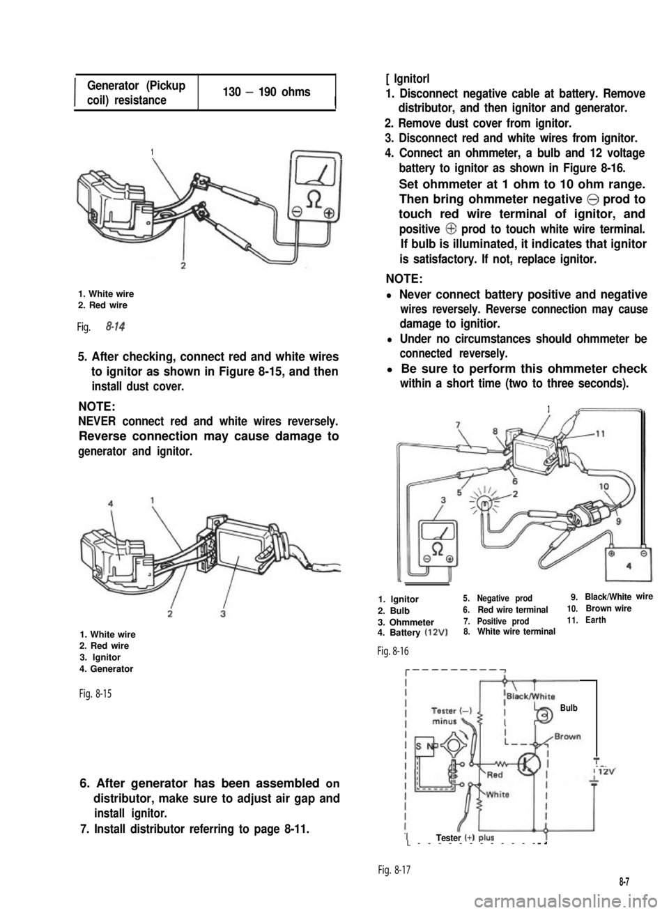
Generator (Pickup
coil) resistance130 - 190 ohmsI
1
1. White wire2. Red wire
Fig. 8-14
5. After checking, connect red and white wires
to ignitor as shown in Figure 8-15, and then
install dust cover.
NOTE:
NEVER connect red and white wires reversely.
Reverse connection may cause damage to
generator and ignitor.
1. White wire2. Red wire
3. lgnitor
4. Generator
Fig. 8-15
6. After generator has been assembled on
distributor, make sure to adjust air gap and
install ignitor.
7. Install distributor referring to page 8-11.
[ Ignitorl
1. Disconnect negative cable at battery. Remove
distributor, and then ignitor and generator.
2. Remove dust cover from ignitor.
3. Disconnect red and white wires from ignitor.
4. Connect an ohmmeter, a bulb and 12 voltage
battery to ignitor as shown in Figure 8-16.
Set ohmmeter at 1 ohm to 10 ohm range.
Then bring ohmmeter negative @ prod to
touch red wire terminal of ignitor, and
positive @ prod to touch white wire terminal.
If bulb is illuminated, it indicates that ignitor
is satisfactory. If not, replace ignitor.
NOTE:
l Never connect battery positive and negative
wires reversely. Reverse connection may cause
damage to ignitior.
l Under no circumstances should ohmmeter be
connected reversely.
l Be sure to perform this ohmmeter check
within a short time (two to three seconds).
1
1. lgnitor5.Negative prod9.Black/Whitewire
2. Bulb6.Red wire terminal10.Brown wire
3. Ohmmeter7.Positive prod11.Earth
4. Battery (12V)8.White wire terminal
Fig. 8-16
c---------~
Bulb
T_-.
ITester (+) PIUSL------------
Fig. 8-17
8-7
Page 220 of 962
![SUZUKI GRAND VITARA 1987 Service User Guide [Checking vacuum advancer]
Remove distributor cap.
Disconnect vacuum hose from vacuum hose 3
way joint, and connect vacuum pump gauge
(0991747910) to its hose. Apply vacuum (ab-
out 400 mmHg). And the SUZUKI GRAND VITARA 1987 Service User Guide [Checking vacuum advancer]
Remove distributor cap.
Disconnect vacuum hose from vacuum hose 3
way joint, and connect vacuum pump gauge
(0991747910) to its hose. Apply vacuum (ab-
out 400 mmHg). And the](/img/20/57437/w960_57437-219.png)
[Checking vacuum advancer]
Remove distributor cap.
Disconnect vacuum hose from vacuum hose 3
way joint, and connect vacuum pump gauge
(0991747910) to its hose. Apply vacuum (ab-
out 400 mmHg). And then with pump stopped,
check to ensure that vacuum pump gauge
indicator remains at the same level, and release
it. Check that generator base plate with gene-
rator moves smoothly. If plate does not move
smoothly, replace defective parts.
Fig. 8-24
1. Distributor drive gear
2. Camshaft3. Cylinder head
Fig. 8-23
@I Vacuum pump gauge (a991 7-47910)
1. Generator base plate
2. Vacuum controller
Distributor Drive Gear
NOTE:
When removing distributor gear case from cylin-
der head, engine oil in cylinder head may come
out. So place waste or receiver under gear case
when removing.
Inspect drive gear for wear.
Worn gear is likely to disturb ignition timing
and therefore must be replaced.
Replacing worn-down drive gear is not enough.
Inspect driven gear (a part of the distributor
assembly), too, and replace it if badly worn
down.
[Important reminders for removal and installa-
tion]
Before removing drive gear from camshaft,
scribe a match mark on this shaft to root
center line of drive gear as shown in Fig.
B-25 and, when mounting replacement drive
gear, refer to this mark.
When pressing replacement drive gear onto
camshaft, be sure to position gear angularly
as shown in Fig. B-25. (align mark on Cam-
shaft scribed in removal with root center of
drive gear)
NOTE:
There is no need to discriminate between two
end faces of drive gear.
Distributor side view
1. Drive gear
2. Camshaft
3. Center line of
45mmhole
4. Center line ofroot5. @5mm hole(Provided on pulleyside of camshaft)
6. Scribed matchmark
7. 5O
Fig. 8-25
l About 30 cc(1.01/l .05 US/Imp 02) of
engine oil must be fed into distributor gear
case after servicing this case, that is, removing
and putting it back. Be sure to add this much
oil before starting engine for the first time
after servicing.
8-11
Page 327 of 962

Rest dummy with dial indicator on surface
plate, and the dial indicator pointer may have
deflected from “0” mark to show a certain
value; read this value, which is “b”.
SURFACE PLATE
Fig. 16-21-4
Add this reading to 94 mm (= “a” + “c”) and,
from the sum, subtract the value marked on
bevel pinion. The remainder is required shim
thickness: (94+“b”) - marked value = required
shim thickness1
Fig. 16-22 I. Marked value
5)Shim stock is available in twelve selective L
thicknesses. Select one or two shim(s) from
the below to obtain the closest thickness to
above required thickness, and insert selected
shim piece(s) into clearance indicated as
Fig. 16-21-3 0.
1.00, 1.03, 1.06, 1.09, 1.12, 1.15, 1.18,
Bevel Pinion Bearing Preload Adjustment
The bevel pinion, as installed in normal manner
in carrier, is required to offer a certain torque
resistance when checked by using prescribed
preload adjuster (special tool @ ) as shown in
Fig. 16-23. This resistance is a “preload,”
which is due to the tighteness of the two tapered
roller bearings by which the pinion is held in the
carrier. And this tighteness is determined prima-
rily by tightening torque of bevel pinion nut.
Adjust preload of bevel pinion bearings as
follows.
1) Install pinion bearings, spacer, bevel pinion,
oil seal and universal joint flange to diffe-
rential carrier.
At this time, be sure to apply gear oil to
bearings lightly and grease to oil seal lip.
2) Tighten bevel pinion nut by hand, and install
special tool to universal joint flange.
3) After turning pinion several times, tighten
pinion nut gradually, while checking pinion
starting torque with spring balance, and stop
tightening when starting torque reaches
specification given below.
4) Caulk bevel pinion nut to prevent it from
loosening.
NOTE:
Bevel pinion bearing preload is adjusted by
tightening bevel pinion nut to crush spacer.
Therefore, be sure to use a new spacer for
adjustment and tighten pinion nut step by step
and check for starting torque (preload) as often
as tightening to prevent over crushing of spacer.
If exceeds specification given below during
adjustment, replace spacer and repeat preload
adjustment procedure. Attempt to decrease
starting torque (preload) by loosening pinion
nut will not do.
The below data are not tightening torque of
pinion nut but pinion bearing preload.
Fig. 16-23 @ Spring balance
@ Special tool (Differential gear preload
adjuster 09922-75221)
16-9
Page 357 of 962

Before giving a test pull to knuckle arm with a
spring balance in the alternative method, in-
stall a large amount of shims on each kingpin to
lighten preload on tapered roller bearing.
Keep on reading the torque, each time decreas-
ing shim thickness a little, and continue this
process until specified torque value is obtained.
(This process protects kingpins because it ensure
that no excessive pull will be applied to bearings
at the onset.) If the process fails to produce
specified torque, that is, if desired torque
resistance does not occur even when shim
thickness has been reduced to zero on each
kingpin, it means that bearings or kingpins are
excessively worn and need replacement.
NOTE:
l Read spring balance indication when knuckle
arm begins to turn. In other words, you are
to read “starting torque.”
l When checking knuckle arm starting torque,
be sure to have axle hub oil seal removed
and tighten king pin bolts to specified torque.
Knuckle arm starting1 .O - 1.8 kg (2.20 - 3.96 lb)
torque (force)without oil seal
Available sizes of0.1,0.5 mm
shim for kingpins(0.004,0.02 in.)
/r--QzL- -\King pin shim
Fig. 17-3-13
Upon completion of this check and/or adjust-
ment, be sure to connect tie rod end to steering
knuckle and install oil seal retainer, oil seal,
felt packing oil seal cover and wheel.
Refer to “INSTALLATION” in this section.
Steering Knuckle Oil Seal
The oil seal used at the spherical sliding joint
between knuckle and inner case accomplishes
additional purposes of keeping out road dust
and of acting as the damper for steering hand-
wheel. As wear of this seal advances, its damping
effect decreases and thus makes front wheel
develop a tendency to “shimmy” not onI9 that
road dust begins to creep into sliding clearance
to promote wear of spherical sliding surfaces.
The oil seal is an expendable item, and must be
replaced at regular intervals.
Fig. 17-3-14
[How to replace oil seal]
1) Remove 8 bolts securing joint seat, and
displace oil seal cover and felt packing inward.
Fig. 17-3-15
17-23
Page 464 of 962

DEFOGGER WIRE
NOTE:
When cleaning the rear window glass, use a
dry cloth to wipe it along the wire direction.
When cleaning the glass, do not use detergent
or abrassive-containing glass cleaner.
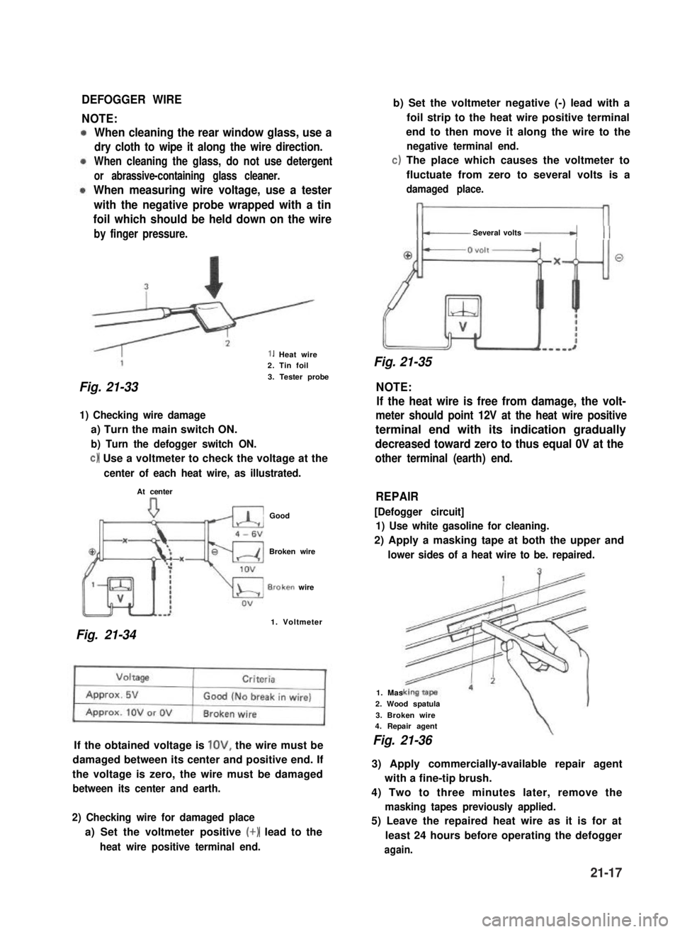
When measuring wire voltage, use a tester
with the negative probe wrapped with a tin
foil which should be held down on the wire
by finger pressure.
1. Heat wire2. Tin foil
3. Tester probe
Fig. 21-33 NOTE:
1) Checking wire damage
a) Turn the main switch ON.
b) Turn the defogger switch ON.
c) Use a voltmeter to check the voltage at the
center of each heat wire, as illustrated.
At center
Good
Broken wire
B.roken wire
1. Voltmeter
Fig. 21-34
If the obtained voltage is lOV, the wire must be
damaged between its center and positive end. If
the voltage is zero, the wire must be damaged
between its center and earth.
2) Checking wire for damaged place
a) Set the voltmeter positive (+) lead to the
heat wire positive terminal end.
b) Set the voltmeter negative (-) lead with a
foil strip to the heat wire positive terminal
end to then move it along the wire to the
negative terminal end.
c) The place which causes the voltmeter to
fluctuate from zero to several volts is a
damaged place.
Several volts -_(( (
Fig. 21-35
If the heat wire is free from damage, the volt-
meter should point 12V at the heat wire positive
terminal end with its indication gradually
decreased toward zero to thus equal 0V at the
other terminal (earth) end.
REPAIR
[Defogger circuit]
1) Use white gasoline for cleaning.
2) Apply a masking tape at both the upper and
lower sides of a heat wire to be. repaired.
1. Mas
2. Wood spatula
3. Broken wire4. Repair agent
Fig. 21-36
3) Apply commercially-available repair agent
with a fine-tip brush.
4) Two to three minutes later, remove the
masking tapes previously applied.
5) Leave the repaired heat wire as it is for at
least 24 hours before operating the defogger
again.
21-17