transmission SUZUKI GRAND VITARA 1987 Service Repair Manual
[x] Cancel search | Manufacturer: SUZUKI, Model Year: 1987, Model line: GRAND VITARA, Model: SUZUKI GRAND VITARA 1987Pages: 962, PDF Size: 27.87 MB
Page 2 of 962
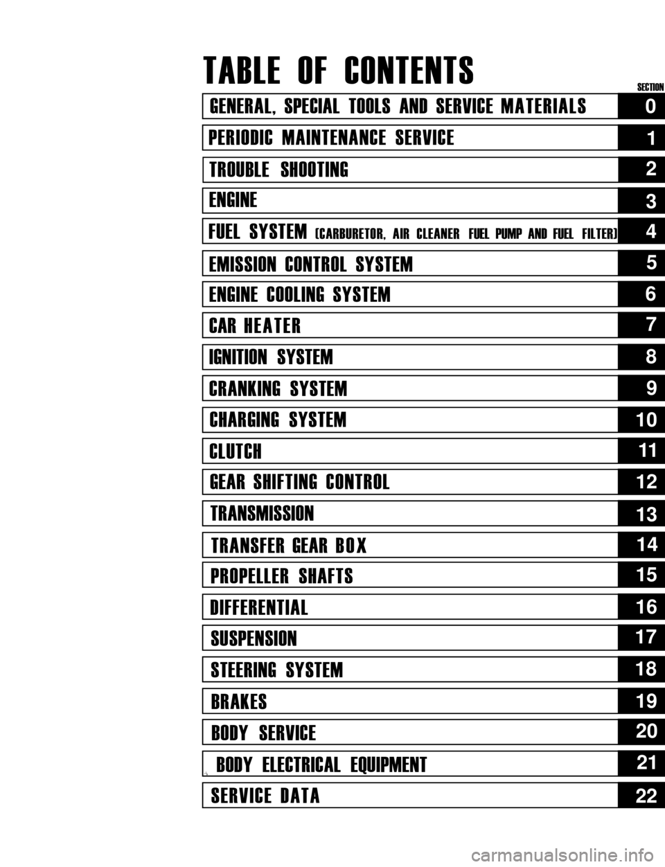
TABLE OF CONTENTS
GENERAL, SPECIAL TOOLS AND SERVICE MATERIALS
PERIODIC MAINTENANCE SERVICE
TROUBLE SHOOTING
ENGINE
FUEL SYSTEM (CARBURETOR, AIR CLEANER FUEL PUMP AND FUEL FILTER)
EMISSION CONTROL SYSTEM
ENGINE COOLING SYSTEM
CAR HEATER
IGNITION SYSTEM
CRANKING SYSTEM
CHARGING SYSTEM
CLUTCH
GEAR SHIFTING CONTROL
TRANSMISSION
TRANSFER GEAR BOX
PROPELLER SHAFTS
DIFFERENTIAL
SUSPENSION
STEERING SYSTEM
BRAKES
BODY SERVICE
,i BODY ELECTRICAL EQUIPMENT
SERVICE DATA
0
1
2
5
6
7
8
9
10
1111
12
13
14
15
16
17
18
19
20
21
22
4
3
SECTION
Page 20 of 962
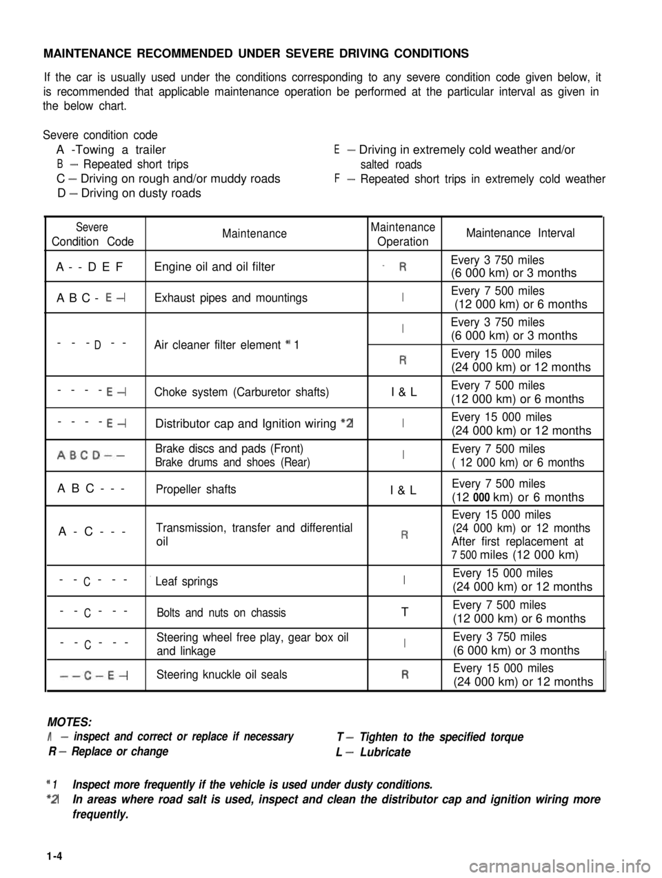
MAINTENANCE RECOMMENDED UNDER SEVERE DRIVING CONDITIONS
If the car is usually used under the conditions corresponding to any severe condition code given below, it
is recommended that applicable maintenance operation be performed at the particular interval as given in
the below chart.
Severe condition code
A -Towing a trailer
B- Repeated short trips
C - Driving on rough and/or muddy roads
D - Driving on dusty roads
E- Driving in extremely cold weather and/or
salted roads
F- Repeated short trips in extremely cold weather
Severe
Condition CodeMaintenanceMaintenance
OperationMaintenance Interval
A--DEFEngine oil and oil filter_ REvery 3 750 miles
(6 000 km) or 3 months
ABC- E-Exhaust pipes and mountingsIEvery 7 500 miles
(12 000 km) or 6 months
IEvery 3 750 miles
D(6 000 km) or 3 months--- --Air cleaner filter element * 1
REvery 15 000 miles
(24 000 km) or 12 months
----E-Choke system (Carburetor shafts)I&LEvery 7 500 miles
(12 000 km) or 6 months
----E-Distributor cap and Ignition wiring “2IEvery 15 000 miles
(24 000 km) or 12 months
ABCD--Brake discs and pads (Front)IEvery 7 500 miles
Brake drums and shoes (Rear)( 12 000 km) or 6 months
ABC---Propeller shaftsI&LEvery 7 500 miles
(12 000 km) or 6 months
Every 15 000 miles
A-C---Transmission, transfer and differential(24 000 km) or 12 months
oilRAfter first replacement at
7 500 miles (12 000 km)
CEvery 15 000 miles-- ---’ Leaf springsI(24 000 km) or 12 months
C-- ---Bolts and nuts on chassisTEvery 7 500 miles
(12 000 km) or 6 months
CSteering wheel free play, gear box oil-- ---and linkageIEvery 3 750 miles
(6 000 km) or 3 months
--C-E-Steering knuckle oil sealsREvery 15 000 miles
(24 000 km) or 12 months
MOTES:
I- inspect and correct or replace if necessary
R - Replace or change
T - Tighten to the specified torque
L - Lubricate
* 1Inspect more frequently if the vehicle is used under dusty conditions.
*2In areas where road salt is used, inspect and clean the distributor cap and ignition wiring more
frequently.
1-4
Page 31 of 962

1) Replace fuel hoses (pipe to fuel pump, pipe to
fuel filter and breather hose) in fuel feed and
return lines with new ones.
2) Remove fuel tank.
3) Replace return hose (tank to return pipe)
with new one.
4) Clamp hoses securely.
5) Install fuel tank referring to p. 4-35.
6) After installation, start engine and check it
for leaks.
27. IDLE SPEED INSPECTION
NOTE:
Before starting engine, place transmission gear
shift lever in “Neutral”, and set parking brake
and block drive wheels.
1) Warm up engine to normal operating tempe-
rature.
2) Check to ensure that idle speed is within
750 - 850 r/min (rpm).
3) If idle speed is not within specified range,
adjust idle speed. Refer to MAINTENANCE
SERVICE (p. 4-26) for procedures to check
and adjust idle speed.
28. IDLE MIXTURE INSPECTION
1) Warm up engine to normal operating tem-
perature.
2) Remove seal rubber of duty check coupler
and connect positive terminal of duty meter
to “Blue/Red” wire and negative terminal to
“Black/Green” wire.
1
1. Duty check coupler
2. Air intake case
3) Set tachometer.
4) Run engine at 1,500 - 2,000 r/min for 30
seconds and bring it to idle speed.
5) Check duty at specified idle speed. If it is out
of specification,adjust it to specification
according to following adjustment procedure.
Specified Duty10-50
at 750 - 850 r/min.I
After inspection, install seal rubber to duty
check coupler.
Idle mixture adjustment procedure is as follows:
1) Remove carburetor from intake manifold
following normal service procedure to gain
access to mixture adjusting screw pin covering
mixture adjusting screw.
2) Drive out mixture adjusting screw pin using
about 4.5 mm (0.18 in) thick iron rod as
shown below.
1-15
Page 36 of 962
3) Check propeller shaft (No. 1, No. 2, No. 3)
flange yoke bolts for tightness, and retighten
them as necessary:
N.mkg-mlb-ftTighteningtorque23-302.3-3.017.0-21.5
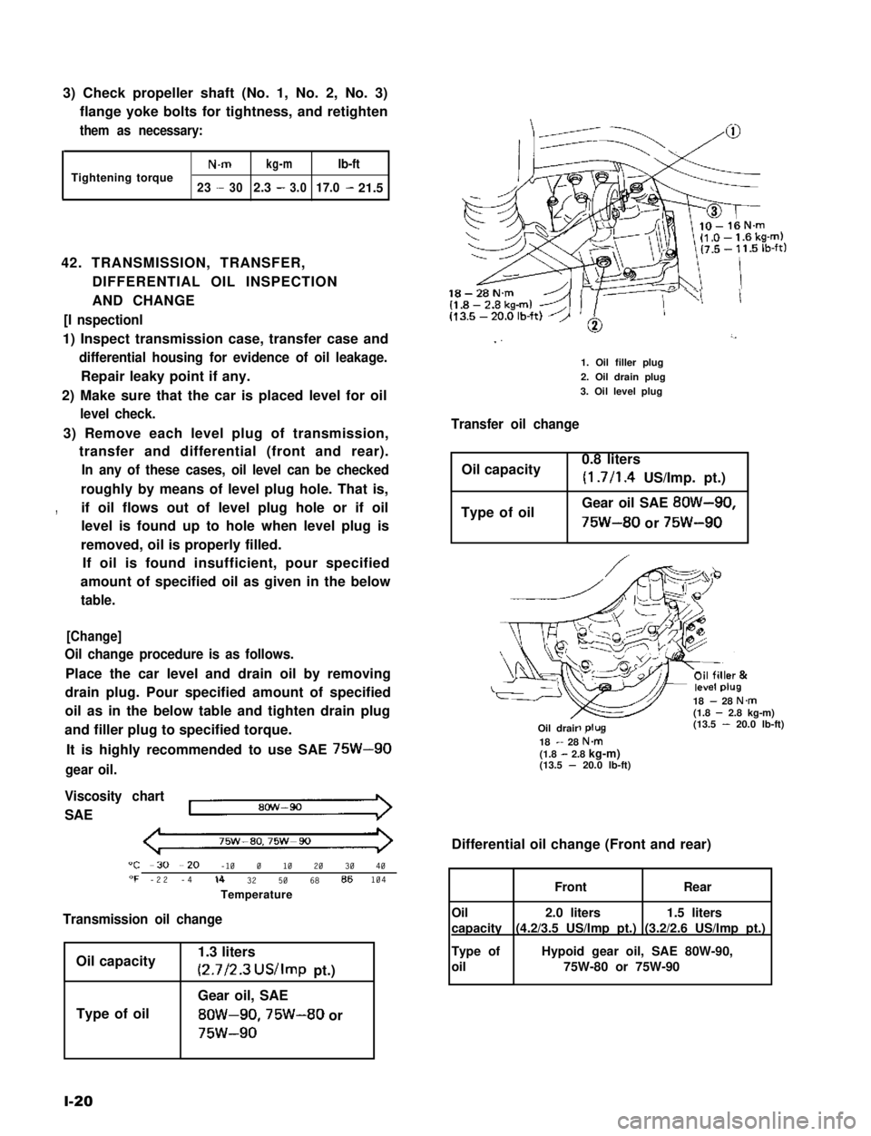
42. TRANSMISSION, TRANSFER,
DIFFERENTIAL OIL INSPECTION
AND CHANGE
[I nspectionl
1) Inspect transmission case, transfer case and
differential housing for evidence of oil leakage.
Repair leaky point if any.
2) Make sure that the car is placed level for oil
level check.
3) Remove each level plug of transmission,
transfer and differential (front and rear).
In any of these cases, oil level can be checked
roughly by means of level plug hole. That is,
,if oil flows out of level plug hole or if oil
level is found up to hole when level plug is
removed, oil is properly filled.
If oil is found insufficient, pour specified
amount of specified oil as given in the below
table.
[Change]
Oil change procedure is as follows.
Place the car level and drain oil by removing
drain plug. Pour specified amount of specified
oil as in the below table and tighten drain plug
and filler plug to specified torque.
It is highly recommended to use SAE 75W-90
gear oil.
Viscosity chart
SAE
75w-ao,75w-90
"C -30 --20 -10 0 10 20 30 40"F -22 -4lb 32 50 68 86104
Temperature
Transmission oil change
Oil capacity
Type of oil
1.3 liters
(2.7/2.3 US/Imp pt.)
Gear oil, SAE
8OW-90,75W-80 or
75w-90
l-20
18-28N.m
I ”’
1. Oil filler plug
2. Oil drain plug
3. Oil level plug
Transfer oil change
Oil capacity0.8 liters
(1.7/l .4 US/Imp. pt.)
Type of oilGear oil SAE 8OW-90,
75W-80 or 75W-90
18 - 28 N.m(1.8 - 2.8 kg-m)(13.5 - 20.0 lb-ft)-R-Oil drair18 - 28 N&(1.8 - 2.8 kg-m)(13.5 - 20.0 lb-ft)
Differential oil change (Front and rear)
1.5 liters
(3.2/2.6 US/Imp pt.)
2.0 liters
(4.2/3.5 US/Imp pt.)
FrontRear
Oil
capacity
Type of
oil
Hypoid gear oil, SAE 80W-90,
75W-80 or 75W-90
Page 38 of 962

FINAL INSPECTION
Carry out road test in safe place.
WARNING:
When carrying out the following road
tests, select a safe place where no man or
no running car is seen so as to prevent any
accident.
1) Engine start
Check engine start for readiness.
2) Clutch
Check the following:
l that clutch is completely released when
depressing clutch pedal,
l that no slipping clutch occurs when releas-
ing pedal and accelerating,
l and that clutch itself is free from any
abnormal condition.
3) Gearshift Lever (Transmission and Transfer)
Check gearshift lever for smooth shifting
to all positions and for good performance of
transmission and transfer in any position.
4) Brake
[Foot brake]
Check the following when depressing brake
pedal while driving;
l that brake works properly,
l that it is free from noise,
l and that braking force applies equally on
all wheels.
[Parking brake]
Check to ensure that parking brake is fully
effective when the car is stopped on the slop
and brake lever is pulled all the way.
5) Steering
Check to ensure that steering wheel is free
from instability, or abnormally heavy feeling
while driving.
1-22
Page 39 of 962

2-1.
2-2.
2-3.
2-4.
2-5.
2-6.
2-7.
2-6.
2-9.
SECTION 2
TROUBLE SHOOTING
CONTENTS
ENGINE...................................................2-2
CARBURETOR...........................................
EXHAUST AND MUFFLER.................................
CLUTCH.................................................2-9
TRANSMISSION..........................................
DIFFERENTIALS.........................................2-11
PROPELLER SHAFTS.....................................2-12
BRAKES.............................................. 2-12
SUSPENSION, STEERING SYSTEM AND TIRES................
STARTING MOTOR.....................................
2-11. ALTERNATOR...........................................
FUEL METER............................................ 2-19
2-14. SPEEDOMETER..........................................2-19
2-15. WATER TEMPERATURE METER.............................2-19
2-9
2-9
2-10
2-14
2-16
2-17
2-18WIPER MOTOR.......................................
2-10.
2-12.
2-13.
2-1
2
Page 48 of 962

Condition
Clutch vibration
Noisy clutch
Grabbing clutch
2-5. TRANSMISSION
Condition
Gears slipping out of
mesh
Gears refusing to dis-
engage
Possible cause
1. Improper clutch pedal free travel
2. Weakened diaphragm spring, or worn spring
tip
3. Damaged or worn splines of transmission
input shaft
4. Front input shaft bearing worn or broken
5. Excessively wobbly clutch disc
6. Clutch facings broken or dirty with oil
1. Glazed (glass-like) clutch facings
2. Clutch facings dirty with oil
3. Wobbly clutch disc, or poor facing contact
4. Weakened torsion springs (in clutchdisc)
5. Clutch disc rivets loose
6. Distorted pressure plate or flywheel surface
7. Weakened engine mounting or loosened
mounting bolt or nut
1. Worn or broken release bearing
2. Front input shaft bearing worn down
3. Excessive rattle of clutch disc hub
4. Cracked clutch disc
5. Pressure plate and diaphragm spring rattling
1. Clutch facings soaked with oil
2. Excessively worn clutch facings
3. Rivet heads showing out of the facing
4. Weakened torsion springs
Possible cause
1. Worn shift fork shaft
2. Worn locating steel balls
3. Weakened springs for locating steel balls
4. Worn shift fork
5. Excessive rattle in thrust direction of gears
6. Worn ring or hub in synchronizers
7. Worn bearings of input shaft, main shaft or
countershaft
1. Weakened or broken synchronizer springs
2. Worn inner groove of synchronizer ring
3. Synchronizer ring seized on. the cone
4.Distorted shift fork shaft or shift fork
Correction
Adjust free travel
Replace
Replace
Replace
Replace
Replace
Repair or replace
Replace
Replace
Replace
Replace the disc
Replace
Retighten or replace
Replace
Replace
Replace the disc
Replace
Replace
Replace
Replace
Replace
Replace
Correction
Replace
Replace
Replace
Replace
Replace
Replace
Replace
Replace
Replace
Replace the ring
Replace.
Dragging clutch
2-10
Page 49 of 962

Condition
Excessive gear noise
Hard shifting
2-6. DIFFERENTIALS
Possible cause
1. Not enough oil in transmission
2. Defective synchronizer
3. Gears rattling in thrust direction
4. Broken or worn bearings
5. Damaged or worn gears
1. Clutch pedal play too large, resulting in a
“dragging clutch”
2. Worn clutch disc facings
3. Clutch disc facings dirty with oil.
4. Distorted or unevenly worn shift fork shaft
5. Broken locating balls
6. Worn synchornizer sleeve or ring
7. Worn synchronizer hub
Condition
Gear noise
Bearing noise
Possible cause
1. Maladjusted backlash between drive pinion
and ring gear
2. Damaged gear teeth or improper mesh of
drive pinion and ring gear
3. Improper tooth contact in the mesh between
drive pinion and ring gear
4. Insufficient or wrong kind of gear oil
5. Ring gear wobbling when turning, or ring
gear securing bolts loose
6. Broken or otherwise damaged teeth of side
gears or differential pinion gears
1. (Constant noise) Insufficient or wrong kind
of gear oil
2. (Constant noise) Damaged or worn bearings
or borne parts
3. (Noise during coasting) Damaged bearings
of rear drive pinion
4. (Noise during turning) Broken bearings
on axle shafts
Correction
Replenish
Replace
Replace
Replace
Replace
Adjust as prescribed
Replace.
Replace.
Replace
Replace
Replace
Replace
Correction
Adjust as prescribed
Replace or adjust
Adjust as prescribed
Replenish or replace
Replace, or retighten
Replace
Replenish or change
Replace.
Replace
Replace
2-11
Page 64 of 962
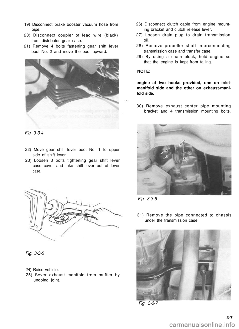
19) Disconnect brake booster vacuum hose from
pipe.
20) Disconnect coupler of lead wire (black) from distributor gear case.
21) Remove 4 bolts fastening gear shift lever boot No. 2 and move the boot upward.Fig. 3-3-4
22) Move gear shift lever boot No. 1 to upperside of shift lever.
23) Loosen 3 bolts tightening gear shift lever case cover and take shift lever out of lever
case.
26) Disconnect clutch cable from engine mount- ing bracket and clutch release lever.
27) Loosen drain plug to drain transmission oil.
28) Remove propeller shaft interconnecting transmission case and transfer case.
29) By using a chain block, hold engine so that the engine is kept from falling.
NOTE:
engine at two hooks provided, one on
inlet-
manifold side and the other on exhaust-mani-
fold side.
30) Remove exhaust center pipe mounting bracket and 4 transmission mounting bolts.
Fig. 3-3-6
31) Remove the pipe connected to chassis
under the transmission case.
Fig. 3-3-5
24) Raise vehicle.25) Sever exhaust manifold from muffler by undoing joint.
Fig. 3-3-7
3-7
Page 65 of 962
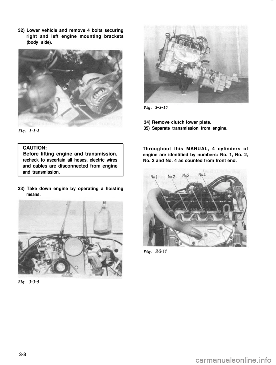
32) Lower vehicle and remove 4 bolts securing
right and left engine mounting brackets(body side).
Fig. 3-3-10
Fig. 3-3-8
CAUTION:Before lifting engine and transmission,
recheck to ascertain all hoses, electric wires
and cables are disconnected from engine
and transmission.
34) Remove clutch lower plate.
35) Separate transmission from engine.
Throughout this MANUAL, 4 cylinders ofengine are identified by numbers: No. 1, No. 2, No. 3 and No. 4 as counted from front end.
33) Take down engine by operating a hoisting
means.
Fig. 3-3-11
Fig. 3-3-9
3-8