heating SUZUKI GRAND VITARA 1987 Service Repair Manual
[x] Cancel search | Manufacturer: SUZUKI, Model Year: 1987, Model line: GRAND VITARA, Model: SUZUKI GRAND VITARA 1987Pages: 962, PDF Size: 27.87 MB
Page 25 of 962

CAUTION:
When changing engine coolant, use mixture
of 56% water and 50% GOLDEN CRUISER
1200for the market where ambient tem-
perature falls lower than -16°C (3°F) in
winter and mixture of 70% water and
30% GOLDEN CRUISER 1200for the
market where ambient temperature doesn’t
fall lower than -16°C (3” F).
Even in a market where no freezing tempe-
rature is anticipated, mixture of 70% water
and 30% GOLDEN CRUISER 1200
should be used for the purpose of corro-
sion protection and lubrication.
7. EXHAUST PIPES AND MOUNTINGS
INSPECTION
1.Drain plug
1. Reservoir tank cap2. Reservoir tank
3. Arrow marks
5) Fill radiator with specified amount of coolant,
and run engine for 2 or 3 minutes at idle.
This drives out any air which may still be
trappedwithincoolingsystem.STOP
ENGINE. Add coolant as necessary until
coolant level reaches the filler throat of
radiator. Reinstall radiator cap.
6) Add coolant to reservoir tank so that the level
aligns with Full mark. Then, reinstall cap
aligning the arrow marks on the tank and cap.
r.
COOLANT CAPACITY
Engine, radiator and4.2 liters
heater(8.9/7.4 US/Imp pt.)
Reservoir tank0.6 liters
(1.3/1.1 US/Imp pt.)
ITotal4.8 liters
(10.1/8.4US/lmp pt.)
WARNING:
To avoid danger of being burned, do not
touch exhaust system when system is hot.
Any service on exhaust system should be
performed when system is cool.
When carrying out periodic maintenance, or the
car is raised for other service, check exhaust
system as follows:
l Check rubber mountings for damage, deterio-
ration, and out of position.
l Check exhaust system for leakage, loose
connections, dents, and damages.
If bolts or nuts are loose, tighten them to
specification. Refer to below chart for torque
specification.
l Check nearby body areas for damaged, miss-
ing, or mispositioned parts, open seams,
holes, loose connections or’ other defects
which could permit exhaust fumes to seep
into the car.
l Make sure that exhaust system components
have enough clearance from the underbody to
avoid overheating and possible damage to the
floor carpet.
l Any defects should be fixed at once.
IBolts and nutTightening torqueI
40-80 N-m
Exhaustpipebolts4.0-6.0 kg-m
29.0-43.0 lb-ft
Muffler nuts
18 - 28 N-m
1.8 - 2.8 kg-m
13.5 - 20.0 lb-ft
Replace center pipe rubber mounting and muffler
rubber mountings with new ones periodically.
l-9
Page 41 of 962

Condition
Poor starting
(Hard starting)
Possible cause
6. Broken valve timing belt
7. Poor valve seating
8. Wrong kind of engine oil
9. Burnt valves
10. Sticky valve stem
Correction
Replace
Repair or replace
Replace
Replace
Correct or replace valve
and guide
Emission control
1. Malfunctioning PCV valve
2. Loose connection or disconnection of
vacuum hoses
Replace.
Connect securely.
3. ECM is poorly grounded.Ground ECM securely
Not enough powerInadequate compression
1. Improper valve clearance
2. Valves not seating tight
3. Valve stems tending to seize
4. Broken or weakened valve spring
5. Piston rings seized in grooves, or broken
6. Worn pistons, rings or cylinders
Adjust
Repair
Replace
Replace
Replace
Replace worn parts and
rebore as necessary
7. Leaky cylinder head gasketReplace
Improperly timed ignition
1. Improper ignition timing
2. Defective spark plug
3. Worn distributor terminals
4. Leaks, loose connection or disconnection of
high tension cord
5. Malfunctioning ignition timing advancers
Adjust
Adjust gap or replace
Dress or replace
Connect or replace as
necessary
Replace
Fuel system out of order
1. Clogged carburetor jets
2. Defective fuel pump
3. Clogged fuel filter
4. Malfunctioning choke system
5. Float level out of adjustment
6. Clogged fuel pipe
7. Clogged fuel tank outlet
8. Loose joint in fuel system
Disassemble and clean
Repair or replace
Replace
Adjust or replace
Adjust
Clean or replace
Clean
Retighten
Abnormal condition in air intake system
1. Air cleaner dirty and clogged
2. Poor returning motion of choke valve
Clean or replace
Repair, adjust or replace
Overheating tendency of engine
1. (Refer to the section entitled “over-
heating.“)
2-3
Page 45 of 962

9
Cond it ionPossible causeCorrection
OverheatingAbnormal condition in ignition system
1. Improper ignition timingAdjust
2. Wrong heat value of spark plugsChange heat value
Abnormal condition in fuel systems
1. Float level set too lowAdjust
2. Clogged jets in carburetorClean
3. Loose inlet manifoldRetighten
Abnormal condition in cooling system,,
1. Not enough coolantRefill
2. Loose or broken fan beltAdjust or replace
3. Erratically working thermostatReplace
4. Poor water pump performanceReplace
5. Leaky radiator coresRepair or replace
Abnormal condition in lubrication system
1. Clogged oil filterReplace
2. Clogged oil strainerClean
3. Deteriorated oil pump performanceReplace
4. Oil leakage from oil pan or pumpRepair
5. Improper engine oil gradeReplace with proper grade
oil
6. Not enough oil in oil panReplenish
Others
1. Dragging brakesRepair or replace
2. Slipping clutchAdjust or replace
3. Blown cylinder head gasketReplace
Engine noiseCrankshaft noise
Note: Before check- 1. Worn-down bearings, resulting in excessivelyReplace
ing the mechanicallarge running clearances
noise, make sure that:2. Worn connecting-rod bearingsReplace
0 Ignition timing is3. Distorted connecting rodsRepair or replace
properly adjusted.4. Worn crankshaft journalsRepair by grinding, or re-
l Specified spark plugplace crankshaft
is used.5. Worn crankpins.Repair by grinding, or re-
l Specified fuel is used.place crankshaft
Noise due to pistons, rings, pins or cylinders
1. Abnormally worn cylinder boresRebore to next oversize
or replace
2. Worn pistons, rings or pinsReplace
3. Pistons tending to seizeReplace
4. Broken piston ringsReplace
, Others
1’. Excessively large camshaft thrust playReplace
2. Excessively large crankshaft thrust clearanceAdjust as prescribed
3. Valve clearance too largeAdjust as prescribed
4. Not enough engine oilReplenish
2-7
Page 197 of 962

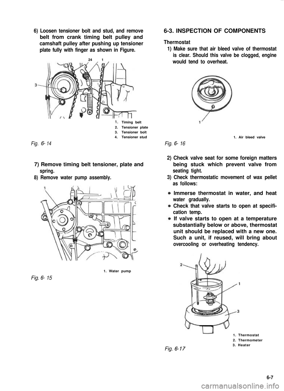
6) Loosen tensioner bolt and stud, and remove
belt from crank timing belt pulley and
camshaft pulley after pushing up tensioner
plate fully with finger as shown in Figure.
24 1
1.Timing belt
2.Tensioner plate3.Tensioner bolt4.Tensioner stud
Fig.6-14
8) Remove water pump assembly.
7) Remove timing belt tensioner, plate and
spring.
1. Water pump
Fig. 6- 15
6-3. INSPECTION OF COMPONENTS
Thermostat
1) Make sure that air bleed valve of thermostat
is clear. Should this valve be clogged, engine
would tend to overheat.
Fig. 6- 16
1. Air bleed valve
2) Check valve seat for some foreign matters
3) Check thermostatic movement of wax pellet
being stuck which prevent valve from
seating tight.
as follows:
Immerse thermostat in water, and heat
water gradually.
Check that valve starts to open at specifi-
cation temp.
If valve starts to open at a temperature
substantially below or above, thermostat
unit should be replaced with a new one.
Such a unit, if reused, will bring about
overcooling or overheating tendency.
1. Thermostat
2. Thermometer
Fig. 6- 173. Heater
6-7
Page 384 of 962

/I
d-
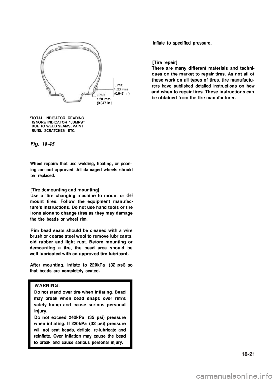
Limitl.Mmm(0.047 in)
1.20 mm(0.047 in 1
*TOTAL INDICATOR READINGIGNORE INDICATOR “JUMPS”DUE TO WELD SEAMS, PAINTRUNS, SCRATCHES, ETC.
Fig. 18-45
Wheel repairs that use welding, heating, or peen-
ing are not approved. All damaged wheels should
be replaced.
[Tire demounting and mounting]
Use a ‘tire changing machine to mount or de-
mount tires. Follow the equipment manufac-
ture’s instructions. Do not use hand tools or tire
irons alone to change tires as they may damage
the tire beads or wheel rim.
Rim bead seats should be cleaned with a wire
brush or coarse steel wool to remove lubricants,
old rubber and light rust. Before mounting or
demounting a tire, the bead area should be
well lubricated with an approved tire lubricant.
After mounting, inflate to 220kPa (32 psi) so
that beads are completely seated.
WARNING:
Do not stand over tire when inflating. Bead
may break when bead snaps over rim’s
safety hump and cause serious personal
injury.
Do not exceed 240kPa (35 psi) pressure
when inflating. If 220kPa (32 psi) pressure
will not seat beads, deflate, re-lubricate and
reinflate. Over inflation may cause the bead
to break and cause serious personal injury.1
Inflate to specified pressure.
[Tire repair]
There are many different materials and techni-
ques on the market to repair tires. As not all of
these work on all types of tires, tire manufactu-
rers have published detailed instructions on how
and when to repair tires. These instructions can
be obtained from the tire manufacturer.
18-21
Page 463 of 962

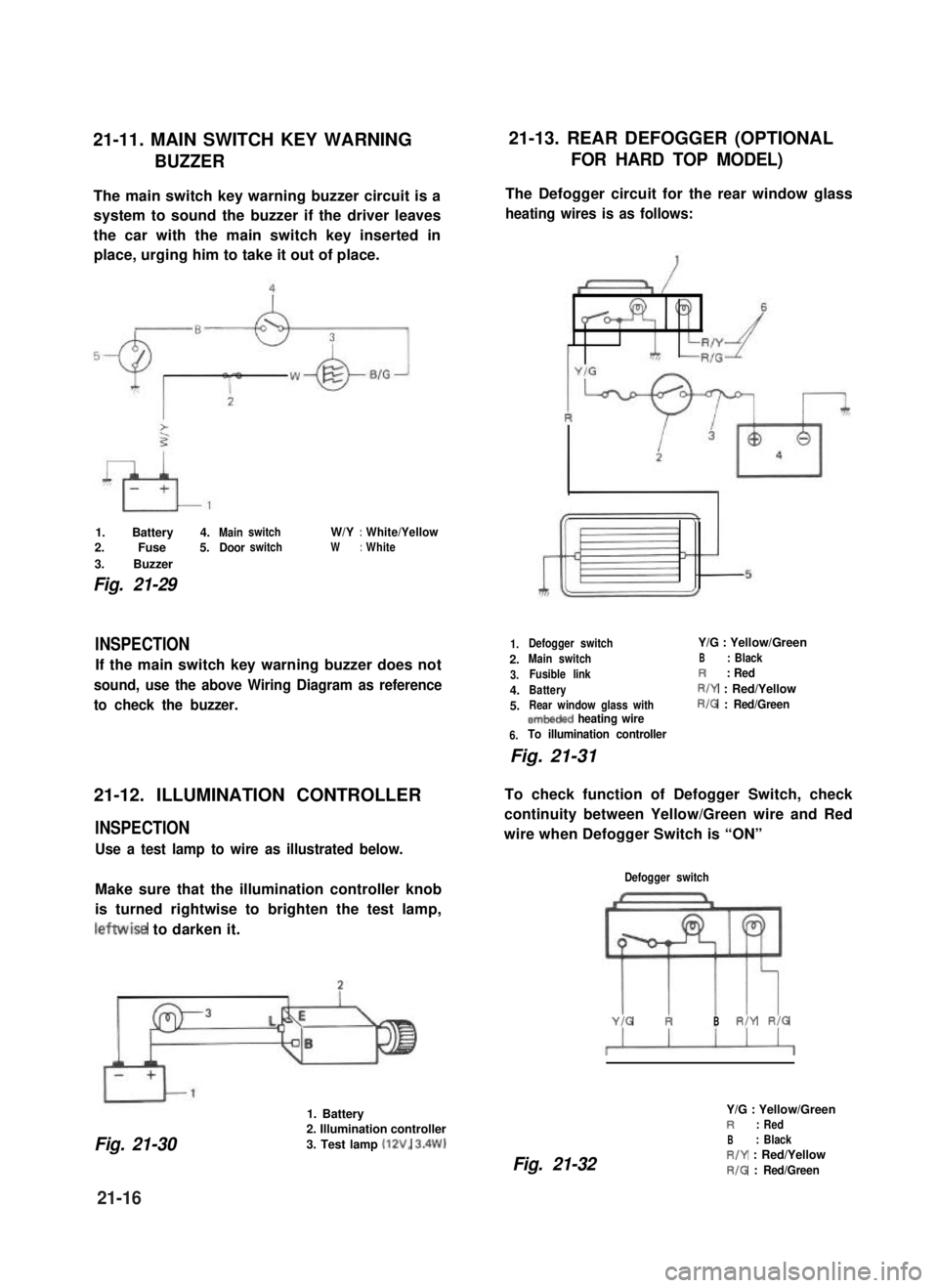
21-11. MAIN SWITCH KEY WARNING21-13. REAR DEFOGGER (OPTIONAL
BUZZERFOR HARD TOP MODEL)
The main switch key warning buzzer circuit is a
system to sound the buzzer if the driver leaves
the car with the main switch key inserted in
place, urging him to take it out of place.
1. Battery 4.MainswitchW/Y:White/Yellow
2. Fuse 5.DoorswitchW:White
3. Buzzer
Fig. 21-29
INSPECTION
If the main switch key warning buzzer does not
sound, use the above Wiring Diagram as reference
to check the buzzer.
21-12. ILLUMINATION CONTROLLER
INSPECTION
Use a test lamp to wire as illustrated below.
Make sure that the illumination controller knob
is turned rightwise to brighten the test lamp,
leftwise to darken it.
1. Battery
Fig. 21-30
2. Illumination controller
3. Test lamp (12V, 3.4W)
The Defogger circuit for the rear window glass
heating wires is as follows:
1.
2.
3.
4.
5.
6.
Defogger switchY/G : Yellow/Green
Main switchB: Black
Fusible linkR: Red
BatteryR/Y : Red/Yellow
Rear window glass withR/G : Red/Greenembeded heating wire
To illumination controller
Fig. 21-31
To check function of Defogger Switch, check
continuity between Yellow/Green wire and Red
wire when Defogger Switch is “ON”
Defogger switch
YIG RBR/Y RIG
Fig. 21-32
Y/G : Yellow/GreenR: Red
B: BlackR/Y : Red/Yellow
R/G : Red/Green
21-16