SUZUKI GRAND VITARA 1999 2.G Owners Manual
Manufacturer: SUZUKI, Model Year: 1999, Model line: GRAND VITARA, Model: SUZUKI GRAND VITARA 1999 2.GPages: 656, PDF Size: 14.31 MB
Page 171 of 656
6-1-10 ENGINE GENERAL INFORMATION AND DIAGNOSIS (H27 ENGINE)
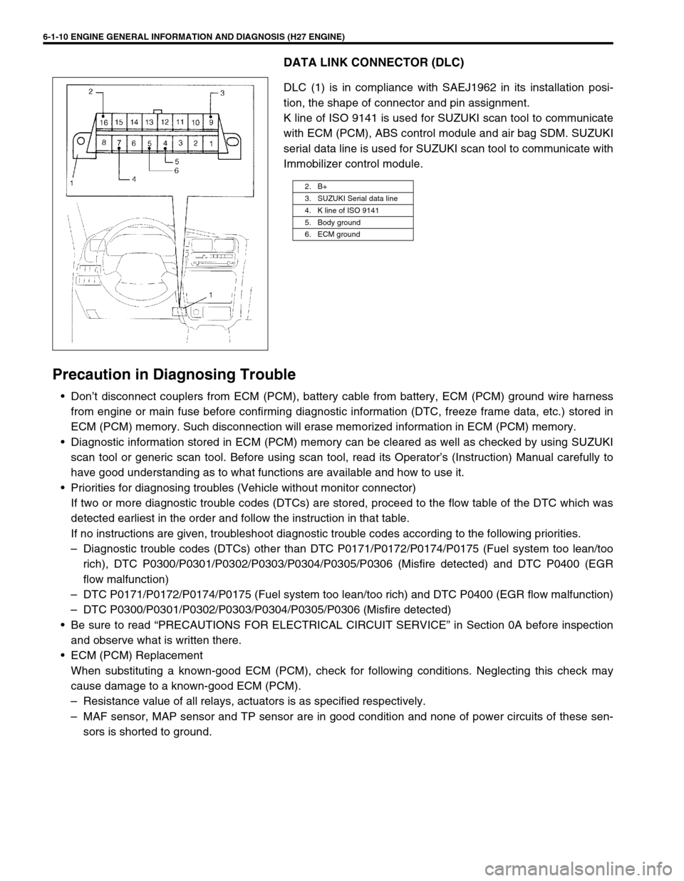
DATA LINK CONNECTOR (DLC)
DLC (1) is in compliance with SAEJ1962 in its installation posi-
tion, the shape of connector and pin assignment.
K line of ISO 9141 is used for SUZUKI scan tool to communicate
with ECM (PCM), ABS control module and air bag SDM. SUZUKI
serial data line is used for SUZUKI scan tool to communicate with
Immobilizer control module.
Precaution in Diagnosing Trouble
• Don’t disconnect couplers from ECM (PCM), battery cable from battery, ECM (PCM) ground wire harness
from engine or main fuse before confirming diagnostic information (DTC, freeze frame data, etc.) stored in
ECM (PCM) memory. Such disconnection will erase memorized information in ECM (PCM) memory.
• Diagnostic information stored in ECM (PCM) memory can be cleared as well as checked by using SUZUKI
scan tool or generic scan tool. Before using scan tool, read its Operator’s (Instruction) Manual carefully to
have good understanding as to what functions are available and how to use it.
• Priorities for diagnosing troubles (Vehicle without monitor connector)
If two or more diagnostic trouble codes (DTCs) are stored, proceed to the flow table of the DTC which was
detected earliest in the order and follow the instruction in that table.
If no instructions are given, troubleshoot diagnostic trouble codes according to the following priorities.
– Diagnostic trouble codes (DTCs) other than DTC P0171/P0172/P0174/P0175 (Fuel system too lean/too
rich), DTC P0300/P0301/P0302/P0303/P0304/P0305/P0306 (Misfire detected) and DTC P0400 (EGR
flow malfunction)
– DTC P0171/P0172/P0174/P0175 (Fuel system too lean/too rich) and DTC P0400 (EGR flow malfunction)
– DTC P0300/P0301/P0302/P0303/P0304/P0305/P0306 (Misfire detected)
• Be sure to read “PRECAUTIONS FOR ELECTRICAL CIRCUIT SERVICE” in Section 0A before inspection
and observe what is written there.
• ECM (PCM) Replacement
When substituting a known-good ECM (PCM), check for following conditions. Neglecting this check may
cause damage to a known-good ECM (PCM).
– Resistance value of all relays, actuators is as specified respectively.
– MAF sensor, MAP sensor and TP sensor are in good condition and none of power circuits of these sen-
sors is shorted to ground.
2. B+
3. SUZUKI Serial data line
4. K line of ISO 9141
5. Body ground
6. ECM ground
Page 172 of 656
ENGINE GENERAL INFORMATION AND DIAGNOSIS (H27 ENGINE) 6-1-11
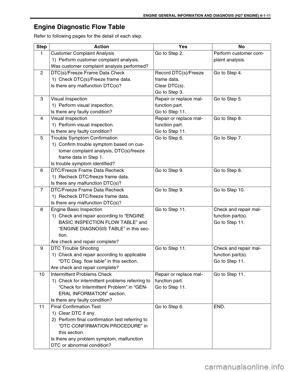
Engine Diagnostic Flow Table
Refer to following pages for the detail of each step.
Step Action Yes No
1 Customer Complaint Analysis
1) Perform customer complaint analysis.
Was customer complaint analysis performed?Go to Step 2. Perform customer com-
plaint analysis.
2 DTC(s)/Freeze Frame Data Check
1) Check DTC(s)/Freeze frame data.
Is there any malfunction DTC(s)?Record DTC(s)/Freeze
frame data.
Clear DTC(s).
Go to Step 3.Go to Step 4.
3 Visual Inspection
1) Perform visual inspection.
Is there any faulty condition?Repair or replace mal-
function part.
Go to Step 11.Go to Step 5.
4 Visual Inspection
1) Perform visual inspection.
Is there any faulty condition?Repair or replace mal-
function part.
Go to Step 11.Go to Step 8.
5 Trouble Symptom Confirmation
1) Confirm trouble symptom based on cus-
tomer complaint analysis, DTC(s)/freeze
frame data in Step 1.
Is trouble symptom identified?Go to Step 6. Go to Step 7.
6 DTC/Freeze Frame Data Recheck
1) Recheck DTC/freeze frame data.
Is there any malfunction DTC(s)?Go to Step 9. Go to Step 8.
7 DTC/Freeze Frame Data Recheck
1) Recheck DTC/freeze frame data.
Is there any malfunction DTC(s)?Go to Step 9. Go to Step 10.
8 Engine Basic Inspection
1) Check and repair according to “ENGINE
BASIC INSPECTION FLOW TABLE” and
“ENGINE DIAGNOSIS TABLE” in this sec-
tion.
Are check and repair complete?Go to Step 11. Check and repair mal-
function part(s).
Go to Step 11.
9 DTC Trouble Shooting
1) Check and repair according to applicable
“DTC Diag. flow table” in this section.
Are check and repair complete?Go to Step 11. Check and repair mal-
function part(s).
Go to Step 11.
10 Intermittent Problems Check
1) Check for intermittent problems referring to
“Check for Intermittent Problem” in “GEN-
ERAL INFORMATION” section.
Is there any faulty condition?Repair or replace mal-
function part.
Go to Step 11.Go to Step 11.
11 Final Confirmation Test
1) Clear DTC if any.
2) Perform final confirmation test referring to
“DTC CONFIRMATION PROCEDURE” in
this section.
Is there any problem symptom, malfunction
DTC or abnormal condition?Go to Step 6. END.
Page 173 of 656
6-1-12 ENGINE GENERAL INFORMATION AND DIAGNOSIS (H27 ENGINE)
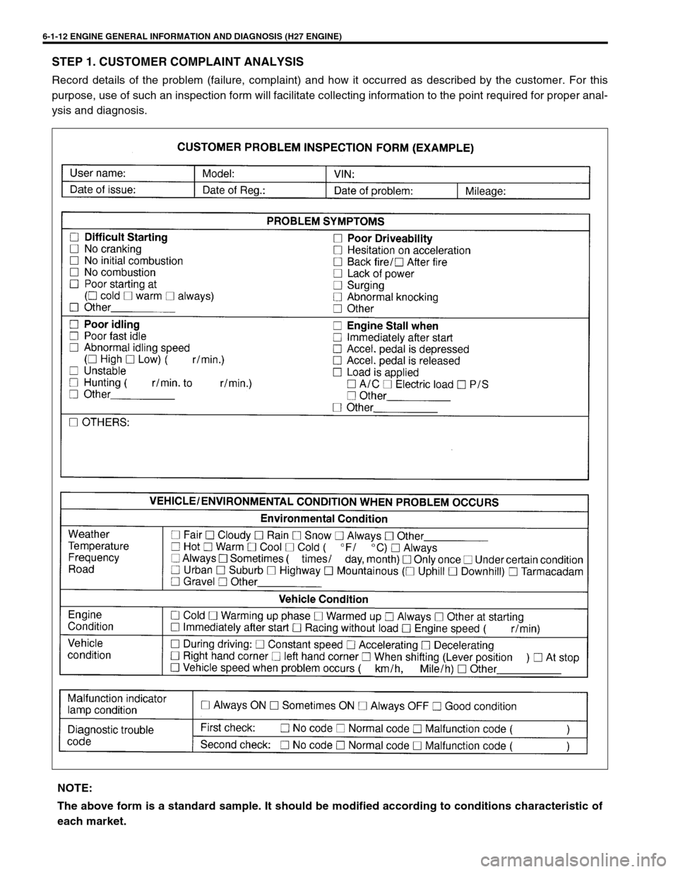
STEP 1. CUSTOMER COMPLAINT ANALYSIS
Record details of the problem (failure, complaint) and how it occurred as described by the customer. For this
purpose, use of such an inspection form will facilitate collecting information to the point required for proper anal-
ysis and diagnosis.
NOTE:
The above form is a standard sample. It should be modified according to conditions characteristic of
each market.
Page 174 of 656
ENGINE GENERAL INFORMATION AND DIAGNOSIS (H27 ENGINE) 6-1-13
STEP 2. DIAGNOSTIC TROUBLE CODE (DTC)/FREEZE FRAME DATA CHECK
First, check DTC, referring to “DIAGNOSTIC TROUBLE CODE CHECK” in this section. If DTC is indicated,
record DTC and freeze frame data.
After that clear DTC referring to “DIAGNOSTIC TROUBLE CODE CLEARANCE” in this section. DTC indicates
malfunction that occurred in the system but does not indicate whether it exists now or it occurred in the past and
the normal condition has been restored now. To check which case applies, check the symptom in question
according to Step 5 and recheck DTC according to Step 6, 7.
Attempt to diagnose a trouble based on DTC in this step only or failure to clear the DTC (including pending DTC)
in this step will lead to incorrect diagnosis, trouble diagnosis of a normal circuit or difficulty in troubleshooting.
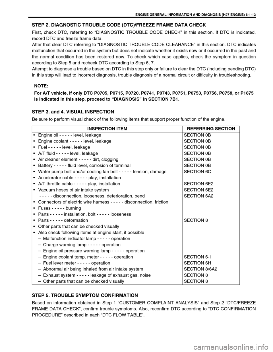
STEP 3. and 4. VISUAL INSPECTION
Be sure to perform visual check of the following items that support proper function of the engine.
STEP 5. TROUBLE SYMPTOM CONFIRMATION
Based on information obtained in Step 1 “CUSTOMER COMPLAINT ANALYSIS” and Step 2 “DTC/FREEZE
FRAME DATA CHECK”, confirm trouble symptoms. Also, reconfirm DTC according to “DTC CONFIRMATION
PROCEDURE” described in each “DTC FLOW TABLE”.NOTE:
For A/T vehicle, if only DTC P0705, P0715, P0720, P0741, P0743, P0751, P0753, P0756, P0758, or P1875
is indicated in this step, proceed to “DIAGNOSIS” in SECTION 7B1.
INSPECTION ITEM REFERRING SECTION
• Engine oil - - - - - level, leakage
• Engine coolant - - - - - level, leakage
• Fuel - - - - - level, leakage
• A/T fluid - - - - - level, leakage
• Air cleaner element - - - - - dirt, clogging
• Battery - - - - - fluid level, corrosion of terminal
• Water pump belt and/or cooling fan belt - - - - - tension, damage
• Accelerator cable - - - - - play, installation
• A/T throttle cable - - - - - play, installation
• Vacuum hoses of air intake system
- - - - - disconnection, looseness, deterioration, bend
• Connectors of electric wire harness - - - - - disconnection, friction
• Fuses - - - - - burning
• Parts - - - - - installation, bolt - - - - - looseness
• Parts - - - - - deformation
• Other parts that can be checked visually
• Also check following items at engine start, if possible
– Malfunction indicator lamp - - - - - operation
– Charge warning lamp - - - - - operation
– Engine oil pressure warning lamp - - - - - operation
– Engine coolant temp. meter - - - - - operation
– Fuel lever meter - - - - - operation
– Abnormal air being inhaled from air intake system
– Exhaust system - - - - - leakage of exhaust gas, noise
– Other parts that can be checked visuallySECTION 0B
SECTION 0B
SECTION 0B
SECTION 0B
SECTION 0B
SECTION 0B
SECTION 6C
SECTION 6E2
SECTION 6E2
SECTION 6A2
SECTION 8
SECTION 6-1
SECTION 6H
SECTION 8/6A2
SECTION 8
SECTION 8
Page 175 of 656
6-1-14 ENGINE GENERAL INFORMATION AND DIAGNOSIS (H27 ENGINE)
STEP 6. AND 7. RECHECKING AND RECORD OF DTC
Refer to “DTC Check” in this section for checking procedure.
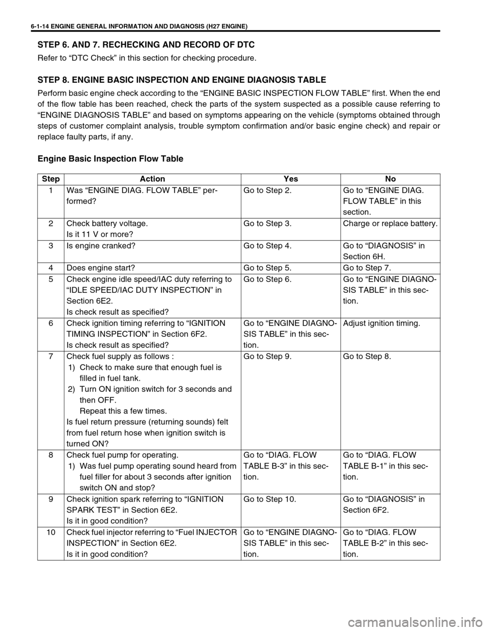
STEP 8. ENGINE BASIC INSPECTION AND ENGINE DIAGNOSIS TABLE
Perform basic engine check according to the “ENGINE BASIC INSPECTION FLOW TABLE” first. When the end
of the flow table has been reached, check the parts of the system suspected as a possible cause referring to
“ENGINE DIAGNOSIS TABLE” and based on symptoms appearing on the vehicle (symptoms obtained through
steps of customer complaint analysis, trouble symptom confirmation and/or basic engine check) and repair or
replace faulty parts, if any.
Engine Basic Inspection Flow Table
Step Action Yes No
1 Was “ENGINE DIAG. FLOW TABLE” per-
formed?Go to Step 2. Go to “ENGINE DIAG.
FLOW TABLE” in this
section.
2 Check battery voltage.
Is it 11 V or more?Go to Step 3. Charge or replace battery.
3 Is engine cranked? Go to Step 4. Go to “DIAGNOSIS” in
Section 6H.
4 Does engine start? Go to Step 5. Go to Step 7.
5 Check engine idle speed/IAC duty referring to
“IDLE SPEED/IAC DUTY INSPECTION” in
Section 6E2.
Is check result as specified?Go to Step 6. Go to “ENGINE DIAGNO-
SIS TABLE” in this sec-
tion.
6 Check ignition timing referring to “IGNITION
TIMING INSPECTION” in Section 6F2.
Is check result as specified?Go to “ENGINE DIAGNO-
SIS TABLE” in this sec-
tion.Adjust ignition timing.
7 Check fuel supply as follows :
1) Check to make sure that enough fuel is
filled in fuel tank.
2) Turn ON ignition switch for 3 seconds and
then OFF.
Repeat this a few times.
Is fuel return pressure (returning sounds) felt
from fuel return hose when ignition switch is
turned ON?Go to Step 9. Go to Step 8.
8 Check fuel pump for operating.
1) Was fuel pump operating sound heard from
fuel filler for about 3 seconds after ignition
switch ON and stop?Go to “DIAG. FLOW
TABLE B-3” in this sec-
tion.Go to “DIAG. FLOW
TABLE B-1” in this sec-
tion.
9 Check ignition spark referring to “IGNITION
SPARK TEST” in Section 6E2.
Is it in good condition?Go to Step 10. Go to “DIAGNOSIS” in
Section 6F2.
10 Check fuel injector referring to “Fuel INJECTOR
INSPECTION” in Section 6E2.
Is it in good condition?Go to “ENGINE DIAGNO-
SIS TABLE” in this sec-
tion.Go to “DIAG. FLOW
TABLE B-2” in this sec-
tion.
Page 176 of 656
ENGINE GENERAL INFORMATION AND DIAGNOSIS (H27 ENGINE) 6-1-15
STEP 9. TROUBLESHOOTING FOR DTC
Based on the DTC indicated in Step 6 or 7 and referring to the applicable DTC diag. flow table in this section,
locate the cause of the trouble, namely in a sensor, switch, wire harness, connector, actuator, ECM (PCM) or
other part and repair or replace faulty parts.
STEP 10. CHECK FOR INTERMITTENT PROBLEM
Check parts where an intermittent trouble is easy to occur (e.g., wire harness, connector, etc.), referring to
“INTERMITTENT AND POOR CONNECTION” in Section 0A and related circuit of DTC recorded in step 2.
STEP 11. FINAL CONFIRMATION TEST
Confirm that the problem symptom has gone and the engine is free from any abnormal conditions. If what has
been repaired is related to the DTC, clear the DTC once, perform DTC confirmation procedure and confirm that
no malfunction DTC (a normal code) is indicated.
Page 177 of 656
6-1-16 ENGINE GENERAL INFORMATION AND DIAGNOSIS (H27 ENGINE)
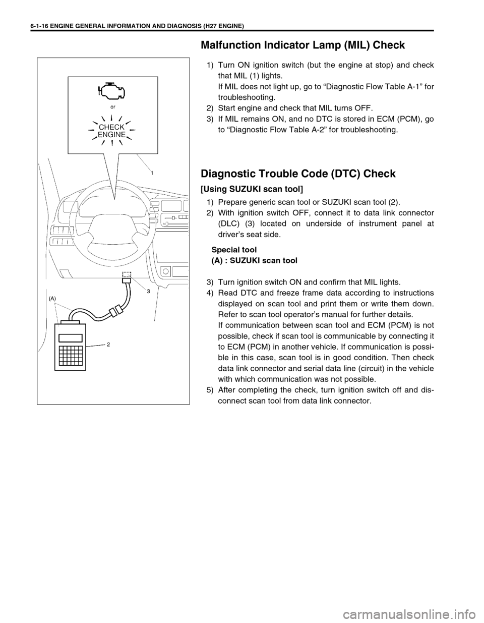
Malfunction Indicator Lamp (MIL) Check
1) Turn ON ignition switch (but the engine at stop) and check
that MIL (1) lights.
If MIL does not light up, go to “Diagnostic Flow Table A-1” for
troubleshooting.
2) Start engine and check that MIL turns OFF.
3) If MIL remains ON, and no DTC is stored in ECM (PCM), go
to “Diagnostic Flow Table A-2” for troubleshooting.
Diagnostic Trouble Code (DTC) Check
[Using SUZUKI scan tool]
1) Prepare generic scan tool or SUZUKI scan tool (2).
2) With ignition switch OFF, connect it to data link connector
(DLC) (3) located on underside of instrument panel at
driver’s seat side.
Special tool
(A) : SUZUKI scan tool
3) Turn ignition switch ON and confirm that MIL lights.
4) Read DTC and freeze frame data according to instructions
displayed on scan tool and print them or write them down.
Refer to scan tool operator’s manual for further details.
If communication between scan tool and ECM (PCM) is not
possible, check if scan tool is communicable by connecting it
to ECM (PCM) in another vehicle. If communication is possi-
ble in this case, scan tool is in good condition. Then check
data link connector and serial data line (circuit) in the vehicle
with which communication was not possible.
5) After completing the check, turn ignition switch off and dis-
connect scan tool from data link connector.
Page 178 of 656
![SUZUKI GRAND VITARA 1999 2.G Owners Manual ENGINE GENERAL INFORMATION AND DIAGNOSIS (H27 ENGINE) 6-1-17
[Without Using SUZUKI Scan Tool] (Vehicle with Monitor
Connector)
1) Check malfunction indicator lamp referring to “Malfunction
Indicato SUZUKI GRAND VITARA 1999 2.G Owners Manual ENGINE GENERAL INFORMATION AND DIAGNOSIS (H27 ENGINE) 6-1-17
[Without Using SUZUKI Scan Tool] (Vehicle with Monitor
Connector)
1) Check malfunction indicator lamp referring to “Malfunction
Indicato](/img/20/7583/w960_7583-177.png)
ENGINE GENERAL INFORMATION AND DIAGNOSIS (H27 ENGINE) 6-1-17
[Without Using SUZUKI Scan Tool] (Vehicle with Monitor
Connector)
1) Check malfunction indicator lamp referring to “Malfunction
Indicator Lamp Check” in this section.
2) With the ignition switch OFF position, disconnect SUZUKI
scan tool if connected and using service wire (4), connect
diagnosis switch terminal (1) to ground terminal (2) in moni-
tor connector (3).
3) With the ignition switch ON position and leaving engine OFF,
read DTC from flashing pattern of malfunction indicator
lamp. Refer to “Diagnostic Trouble Code Table”.
If lamp remains ON, go to “Diagnostic Flow Table A-4”.
4) After completing the check, turn the ignition switch OFF posi-
tion and disconnect service wire from monitor coupler.
Diagnostic Trouble Code (DTC) Clearance
[Using scan tool]
1) With ignition switch OFF, connect generic scan tool or
SUZUKI scan tool to data link connector (DLC).
2) Turn ignition switch ON.
3) Erase DTC according to instructions displayed on scan tool.
Freeze frame data is cleared with the DTC. Refer to scan tool
operator’s manual for further details.
4) After completing the clearance, turn ignition switch off and
disconnect scan tool from data link connector. NOTE:
If abnormality or malfunction lies in two or more areas,
malfunction indicator lamp indicates applicable codes
three times each.
And flashing of these codes is repeated as long as
diagnosis terminal is grounded and ignition switch is
held at ON position.
Take a note of diagnostic trouble code indicated first.
NOTE:
DTC and freeze frame data stored in ECM (PCM) memory
are also cleared in following cases. Be careful not to
clear them before keeping their record.
When power to ECM (PCM) is cut off (by disconnecting
battery cable, removing fuse or disconnecting ECM
(PCM) connectors)
When the same malfunction (DTC) is not detected
again during 40 engine warm-up cycles (refer to
“WARM-UP CYCLE” of “ON-BOARD DIAGNOSTIC SYS-
TEM” in this section) (Vehicle without monitor connec-
tor)
Page 179 of 656
![SUZUKI GRAND VITARA 1999 2.G Owners Manual 6-1-18 ENGINE GENERAL INFORMATION AND DIAGNOSIS (H27 ENGINE)
[Without using scan tool]
1) Turn the ignition switch OFF position.
2) Disconnect battery negative cable for specified time below to
erase SUZUKI GRAND VITARA 1999 2.G Owners Manual 6-1-18 ENGINE GENERAL INFORMATION AND DIAGNOSIS (H27 ENGINE)
[Without using scan tool]
1) Turn the ignition switch OFF position.
2) Disconnect battery negative cable for specified time below to
erase](/img/20/7583/w960_7583-178.png)
6-1-18 ENGINE GENERAL INFORMATION AND DIAGNOSIS (H27 ENGINE)
[Without using scan tool]
1) Turn the ignition switch OFF position.
2) Disconnect battery negative cable for specified time below to
erase diagnostic trouble code stored in ECM memory and
reconnect it.
Time required to erase DTC:
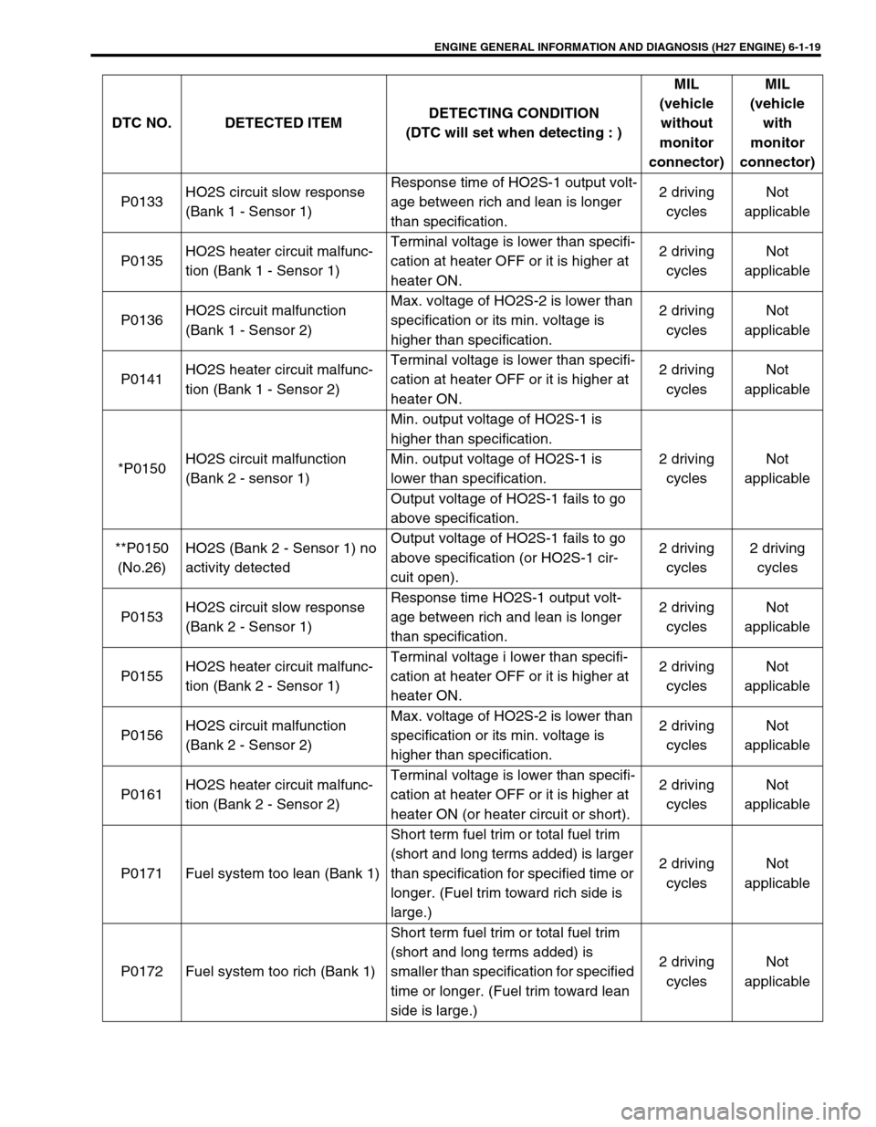
Diagnostic Trouble Code (DTC) Table
Ambient
temperatureTime to cut power to ECM
Over 0°C (32°F) 30 sec. or longer
Under 0°C
(32°F)Not specifiable.
Select a place with higher than 0°C
(32°F) temperature.
DTC NO. DETECTED ITEMDETECTING CONDITION
(DTC will set when detecting : )MIL
(vehicle
without
monitor
connector)MIL
(vehicle
with
monitor
connector)
P0100
(No.34)
Mass air flow circuit malfunc-
tionSensor output too low
1 driving
cycle1 driving
cycle
P0100
(No.33)Sensor output too high
P0110
(No.25)
Intake air temp. circuit mal-
functionIntake air temp. circuit low input
1 driving
cycle1 driving
cycle
P0110
(No.23)Intake air temp. circuit high input
P0115
(No.15)
Engine coolant temp. circuit
malfunctionEngine coolant temp. circuit low input
1 driving
cycle1 driving
cycle
P0115
(No.14)Engine coolant temp. circuit high input
P0120
(No.22)
Throttle position circuit mal-
functionThrottle position circuit low input
1 driving
cycle1 driving
cycle
P0120
(No.21)Throttle position circuit high input
P0121Throttle position circuit perfor-
mance problemPoor performance of TP sensor2 driving
cyclesNot
applicable
*P0130HO2S circuit malfunction
(Bank 1 - Sensor 1)Min. output voltage of HO2S-1 is
higher than specification.
2 driving
cyclesNot
applicable Min. output voltage of HO2S-1 is
lower than specification.
Output voltage of HO2S-1 fails to go
above specification.
**P0130
(No.13)HO2S (Bank 1 - Sensor 1) no
activity detectedOutput voltage of HO2S-1 fails to go
above specification (or HO2S-1 cir-
cuit open).2 driving
cycles2 driving
cycles
Page 180 of 656
ENGINE GENERAL INFORMATION AND DIAGNOSIS (H27 ENGINE) 6-1-19
P0133HO2S circuit slow response
(Bank 1 - Sensor 1)Response time of HO2S-1 output volt-
age between rich and lean is longer
than specification.2 driving
cyclesNot
applicable
P0135HO2S heater circuit malfunc-
tion (Bank 1 - Sensor 1)Terminal voltage is lower than specifi-
cation at heater OFF or it is higher at
heater ON.2 driving
cyclesNot
applicable
P0136HO2S circuit malfunction
(Bank 1 - Sensor 2)Max. voltage of HO2S-2 is lower than
specification or its min. voltage is
higher than specification.2 driving
cyclesNot
applicable
P0141HO2S heater circuit malfunc-
tion (Bank 1 - Sensor 2)Terminal voltage is lower than specifi-
cation at heater OFF or it is higher at
heater ON.2 driving
cyclesNot
applicable
*P0150HO2S circuit malfunction
(Bank 2 - sensor 1)Min. output voltage of HO2S-1 is
higher than specification.
2 driving
cyclesNot
applicable Min. output voltage of HO2S-1 is
lower than specification.
Output voltage of HO2S-1 fails to go
above specification.
**P0150
(No.26)HO2S (Bank 2 - Sensor 1) no
activity detectedOutput voltage of HO2S-1 fails to go
above specification (or HO2S-1 cir-
cuit open).2 driving
cycles2 driving
cycles
P0153HO2S circuit slow response
(Bank 2 - Sensor 1)Response time HO2S-1 output volt-
age between rich and lean is longer
than specification.2 driving
cyclesNot
applicable
P0155HO2S heater circuit malfunc-
tion (Bank 2 - Sensor 1)Terminal voltage i lower than specifi-
cation at heater OFF or it is higher at
heater ON.2 driving
cyclesNot
applicable
P0156HO2S circuit malfunction
(Bank 2 - Sensor 2)Max. voltage of HO2S-2 is lower than
specification or its min. voltage is
higher than specification.2 driving
cyclesNot
applicable
P0161HO2S heater circuit malfunc-
tion (Bank 2 - Sensor 2)Terminal voltage is lower than specifi-
cation at heater OFF or it is higher at
heater ON (or heater circuit or short).2 driving
cyclesNot
applicable
P0171 Fuel system too lean (Bank 1)Short term fuel trim or total fuel trim
(short and long terms added) is larger
than specification for specified time or
longer. (Fuel trim toward rich side is
large.)2 driving
cyclesNot
applicable
P0172 Fuel system too rich (Bank 1)Short term fuel trim or total fuel trim
(short and long terms added) is
smaller than specification for specified
time or longer. (Fuel trim toward lean
side is large.)2 driving
cyclesNot
applicable DTC NO. DETECTED ITEMDETECTING CONDITION
(DTC will set when detecting : )MIL
(vehicle
without
monitor
connector)MIL
(vehicle
with
monitor
connector)