SUZUKI GRAND VITARA 1999 2.G Owners Manual
Manufacturer: SUZUKI, Model Year: 1999, Model line: GRAND VITARA, Model: SUZUKI GRAND VITARA 1999 2.GPages: 656, PDF Size: 14.31 MB
Page 141 of 656
5E2-16 ANTILOCK BRAKE SYSTEM (ABS)
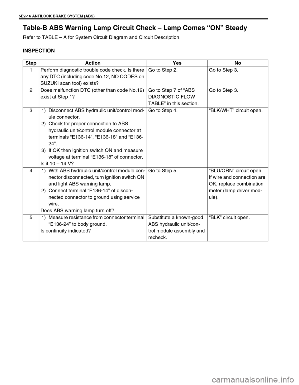
Table-B ABS Warning Lamp Circuit Check – Lamp Comes “ON” Steady
Refer to TABLE – A for System Circuit Diagram and Circuit Description.
INSPECTION
Step Action Yes No
1 Perform diagnostic trouble code check. Is there
any DTC (including code No.12, NO CODES on
SUZUKI scan tool) exists?Go to Step 2. Go to Step 3.
2 Does malfunction DTC (other than code No.12)
exist at Step 1?Go to Step 7 of “ABS
DIAGNOSTIC FLOW
TABLE” in this section.Go to Step 3.
3 1) Disconnect ABS hydraulic unit/control mod-
ule connector.
2) Check for proper connection to ABS
hydraulic unit/control module connector at
terminals “E136-14”, “E136-18” and “E136-
24”.
3) If OK then ignition switch ON and measure
voltage at terminal “E136-18” of connector.
Is it 10 – 14 V?Go to Step 4.“BLK/WHT” circuit open.
4 1) With ABS hydraulic unit/control module con-
nector disconnected, turn ignition switch ON
and light ABS warning lamp.
2) Connect terminal “E136-14” of discon-
nected connector to ground using service
wire.
Does ABS warning lamp turn off?Go to Step 5.“BLU/ORN” circuit open.
If wire and connection are
OK, replace combination
meter (lamp driver mod-
ule).
5 1) Measure resistance from connector terminal
“E136-24” to body ground.
Is continuity indicated?Substitute a known-good
ABS hydraulic unit/con-
trol module assembly and
recheck.“BLK” circuit open.
Page 142 of 656
ANTILOCK BRAKE SYSTEM (ABS) 5E2-17
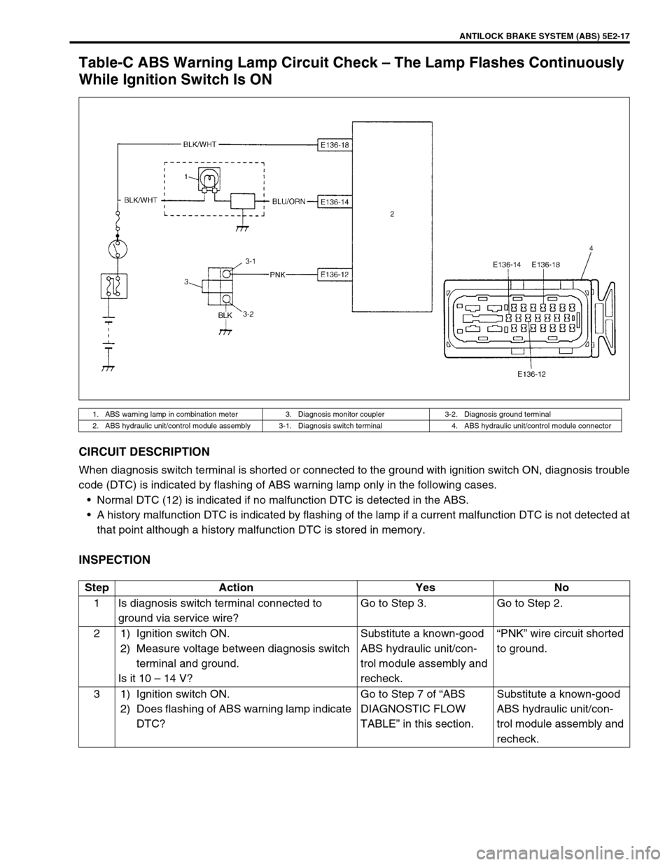
Table-C ABS Warning Lamp Circuit Check – The Lamp Flashes Continuously
While Ignition Switch Is ON
CIRCUIT DESCRIPTION
When diagnosis switch terminal is shorted or connected to the ground with ignition switch ON, diagnosis trouble
code (DTC) is indicated by flashing of ABS warning lamp only in the following cases.
Normal DTC (12) is indicated if no malfunction DTC is detected in the ABS.
A history malfunction DTC is indicated by flashing of the lamp if a current malfunction DTC is not detected at
that point although a history malfunction DTC is stored in memory.
INSPECTION
1. ABS warning lamp in combination meter 3. Diagnosis monitor coupler 3-2. Diagnosis ground terminal
2. ABS hydraulic unit/control module assembly 3-1. Diagnosis switch terminal 4. ABS hydraulic unit/control module connector
Step Action Yes No
1 Is diagnosis switch terminal connected to
ground via service wire?Go to Step 3. Go to Step 2.
2 1) Ignition switch ON.
2) Measure voltage between diagnosis switch
terminal and ground.
Is it 10 – 14 V?Substitute a known-good
ABS hydraulic unit/con-
trol module assembly and
recheck.“PNK” wire circuit shorted
to ground.
3 1) Ignition switch ON.
2) Does flashing of ABS warning lamp indicate
DTC?Go to Step 7 of “ABS
DIAGNOSTIC FLOW
TABLE” in this section.Substitute a known-good
ABS hydraulic unit/con-
trol module assembly and
recheck.
Page 143 of 656
5E2-18 ANTILOCK BRAKE SYSTEM (ABS)
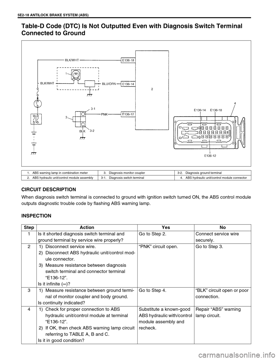
Table-D Code (DTC) Is Not Outputted Even with Diagnosis Switch Terminal
Connected to Ground
CIRCUIT DESCRIPTION
When diagnosis switch terminal is connected to ground with ignition switch turned ON, the ABS control module
outputs diagnostic trouble code by flashing ABS warning lamp.
INSPECTION
1. ABS warning lamp in combination meter 3. Diagnosis monitor coupler 3-2. Diagnosis ground terminal
2. ABS hydraulic unit/control module assembly 3-1. Diagnosis switch terminal 4. ABS hydraulic unit/control module connector
Step Action Yes No
1 Is it shorted diagnosis switch terminal and
ground terminal by service wire properly?Go to Step 2. Connect service wire
securely.
2 1) Disconnect service wire.
2) Disconnect ABS hydraulic unit/control mod-
ule connector.
3) Measure resistance between diagnosis
switch terminal and connector terminal
“E136-12”.
Is it infinite (∞)?“PNK” circuit open. Go to Step 3.
3 1) Measure resistance between ground termi-
nal of monitor coupler and body ground.
Is continuity indicated?Go to Step 4.“BLK” circuit open or poor
connection.
4 1) Check for proper connection to ABS
hydraulic unit/control module at terminal
“E136-12”.
2) If OK, then check ABS warning lamp circuit
referring to TABLE A, B and C.
Is it in good condition?Substitute a known-good
ABS hydraulic with/control
module assembly and
recheck.Repair “ABS” warning
lamp circuit.
Page 144 of 656
ANTILOCK BRAKE SYSTEM (ABS) 5E2-19
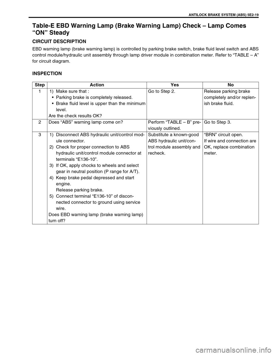
Table-E EBD Warning Lamp (Brake Warning Lamp) Check – Lamp Comes
“ON” Steady
CIRCUIT DESCRIPTION
EBD warning lamp (brake warning lamp) is controlled by parking brake switch, brake fluid level switch and ABS
control module/hydraulic unit assembly through lamp driver module in combination meter. Refer to “TABLE – A”
for circuit diagram.
INSPECTION
Step Action Yes No
1 1) Make sure that :
Parking brake is completely released.
Brake fluid level is upper than the minimum
level.
Are the check results OK?Go to Step 2. Release parking brake
completely and/or replen-
ish brake fluid.
2Does “ABS” warning lamp come on? Perform “TABLE – B” pre-
viously outlined.Go to Step 3.
3 1) Disconnect ABS hydraulic unit/control mod-
ule connector.
2) Check for proper connection to ABS
hydraulic unit/control module connector at
terminals “E136-10”.
3) If OK, apply chocks to wheels and select
gear in neutral position (P range for A/T).
4) Keep brake pedal depressed and start
engine.
Release parking brake.
5) Connect terminal “E136-10” of discon-
nected connector to ground using service
wire.
Does EBD warning lamp (brake warning lamp)
turn off?Substitute a known-good
ABS hydraulic unit/con-
trol module assembly and
recheck.“BRN” circuit open.
If wire and connection are
OK, replace combination
meter.
Page 145 of 656
5E2-20 ANTILOCK BRAKE SYSTEM (ABS)
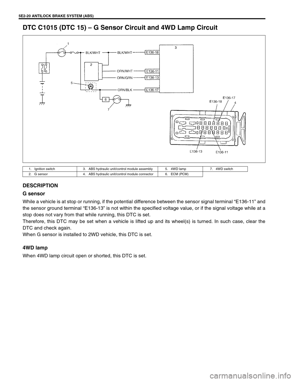
DTC C1015 (DTC 15) – G Sensor Circuit and 4WD Lamp Circuit
DESCRIPTION
G sensor
While a vehicle is at stop or running, if the potential difference between the sensor signal terminal “E136-11” and
the sensor ground terminal “E136-13” is not within the specified voltage value, or if the signal voltage while at a
stop does not vary from that while running, this DTC is set.
Therefore, this DTC may be set when a vehicle is lifted up and its wheel(s) is turned. In such case, clear the
DTC and check again.
When G sensor is installed to 2WD vehicle, this DTC is set.
4WD lamp
When 4WD lamp circuit open or shorted, this DTC is set.
1. Ignition switch 3. ABS hydraulic unit/control module assembly 5. 4WD lamp 7. 4WD switch
2. G sensor 4. ABS hydraulic unit/control module connector 6. ECM (PCM)
Page 146 of 656
ANTILOCK BRAKE SYSTEM (ABS) 5E2-21
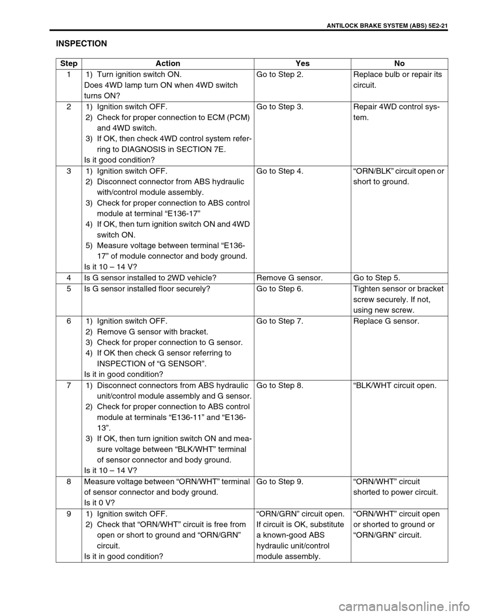
INSPECTION
Step Action Yes No
1 1) Turn ignition switch ON.
Does 4WD lamp turn ON when 4WD switch
turns ON?Go to Step 2. Replace bulb or repair its
circuit.
2 1) Ignition switch OFF.
2) Check for proper connection to ECM (PCM)
and 4WD switch.
3) If OK, then check 4WD control system refer-
ring to DIAGNOSIS in SECTION 7E.
Is it good condition?Go to Step 3. Repair 4WD control sys-
tem.
3 1) Ignition switch OFF.
2) Disconnect connector from ABS hydraulic
with/control module assembly.
3) Check for proper connection to ABS control
module at terminal “E136-17”
4) If OK, then turn ignition switch ON and 4WD
switch ON.
5) Measure voltage between terminal “E136-
17” of module connector and body ground.
Is it 10 – 14 V?Go to Step 4.“ORN/BLK” circuit open or
short to ground.
4 Is G sensor installed to 2WD vehicle? Remove G sensor. Go to Step 5.
5 Is G sensor installed floor securely? Go to Step 6. Tighten sensor or bracket
screw securely. If not,
using new screw.
6 1) Ignition switch OFF.
2) Remove G sensor with bracket.
3) Check for proper connection to G sensor.
4) If OK then check G sensor referring to
INSPECTION of “G SENSOR”.
Is it in good condition?Go to Step 7. Replace G sensor.
7 1) Disconnect connectors from ABS hydraulic
unit/control module assembly and G sensor.
2) Check for proper connection to ABS control
module at terminals “E136-11” and “E136-
13”.
3) If OK, then turn ignition switch ON and mea-
sure voltage between “BLK/WHT” terminal
of sensor connector and body ground.
Is it 10 – 14 V?Go to Step 8.“BLK/WHT circuit open.
8 Measure voltage between “ORN/WHT” terminal
of sensor connector and body ground.
Is it 0 V?Go to Step 9.“ORN/WHT” circuit
shorted to power circuit.
9 1) Ignition switch OFF.
2) Check that “ORN/WHT” circuit is free from
open or short to ground and “ORN/GRN”
circuit.
Is it in good condition?“ORN/GRN” circuit open.
If circuit is OK, substitute
a known-good ABS
hydraulic unit/control
module assembly.“ORN/WHT” circuit open
or shorted to ground or
“ORN/GRN” circuit.
Page 147 of 656
5E2-22 ANTILOCK BRAKE SYSTEM (ABS)
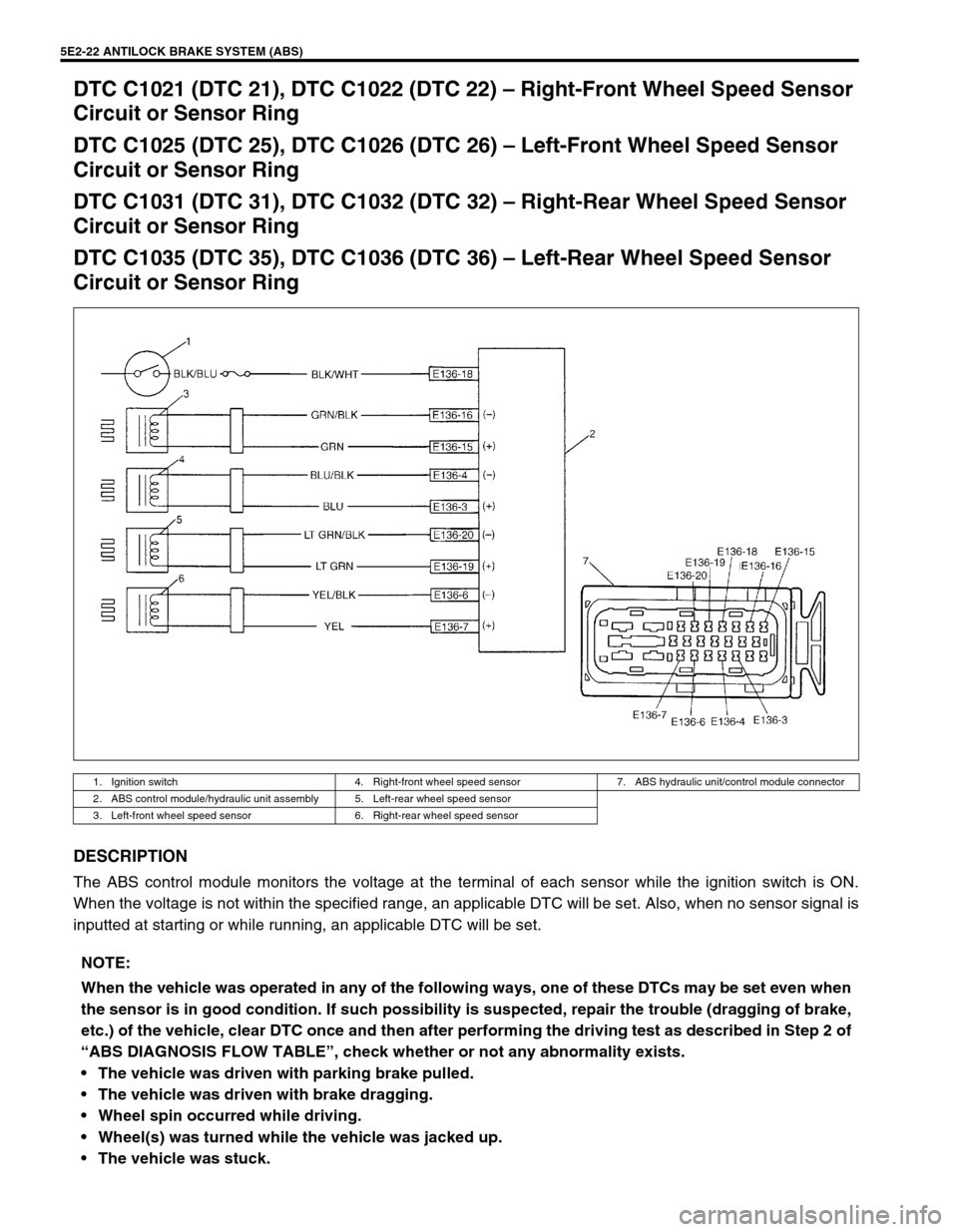
DTC C1021 (DTC 21), DTC C1022 (DTC 22) – Right-Front Wheel Speed Sensor
Circuit or Sensor Ring
DTC C1025 (DTC 25), DTC C1026 (DTC 26) – Left-Front Wheel Speed Sensor
Circuit or Sensor Ring
DTC C1031 (DTC 31), DTC C1032 (DTC 32) – Right-Rear Wheel Speed Sensor
Circuit or Sensor Ring
DTC C1035 (DTC 35), DTC C1036 (DTC 36) – Left-Rear Wheel Speed Sensor
Circuit or Sensor Ring
DESCRIPTION
The ABS control module monitors the voltage at the terminal of each sensor while the ignition switch is ON.
When the voltage is not within the specified range, an applicable DTC will be set. Also, when no sensor signal is
inputted at starting or while running, an applicable DTC will be set.
1. Ignition switch 4. Right-front wheel speed sensor 7. ABS hydraulic unit/control module connector
2. ABS control module/hydraulic unit assembly 5. Left-rear wheel speed sensor
3. Left-front wheel speed sensor 6. Right-rear wheel speed sensor
NOTE:
When the vehicle was operated in any of the following ways, one of these DTCs may be set even when
the sensor is in good condition. If such possibility is suspected, repair the trouble (dragging of brake,
etc.) of the vehicle, clear DTC once and then after performing the driving test as described in Step 2 of
“ABS DIAGNOSIS FLOW TABLE”, check whether or not any abnormality exists.
The vehicle was driven with parking brake pulled.
The vehicle was driven with brake dragging.
Wheel spin occurred while driving.
Wheel(s) was turned while the vehicle was jacked up.
The vehicle was stuck.
Page 148 of 656
ANTILOCK BRAKE SYSTEM (ABS) 5E2-23
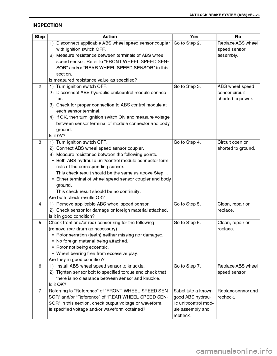
INSPECTION
Step Action Yes No
1 1) Disconnect applicable ABS wheel speed sensor coupler
with ignition switch OFF.
2) Measure resistance between terminals of ABS wheel
speed sensor. Refer to “FRONT WHEEL SPEED SEN-
SOR” and/or “REAR WHEEL SPEED SENSOR” in this
section.
Is measured resistance value as specified?Go to Step 2. Replace ABS wheel
speed sensor
assembly.
2 1) Turn ignition switch OFF.
2) Disconnect ABS hydraulic unit/control module connec-
tor.
3) Check for proper connection to ABS control module at
each sensor terminal.
4) If OK, then turn ignition switch ON and measure voltage
between sensor terminal of module connector and body
ground.
Is it 0V?Go to Step 3. ABS wheel speed
sensor circuit
shorted to power.
3 1) Turn ignition switch OFF.
2) Connect ABS wheel speed sensor coupler.
3) Measure resistance between the following points.
Both ABS hydraulic unit/control module connector termi-
nals of the corresponding sensor.
This check result should be the same as above Step 1.
Either terminal of wheel speed sensor coupler and body
ground.
This check result should be no continuity.
Are both check results OK?Go to Step 4. Circuit open or
shorted to ground.
4 1) Remove applicable ABS wheel speed sensor.
2) Check sensor for damage or foreign material attached.
Is it in good condition?Go to Step 5. Clean, repair or
replace.
5 Check front and/or rear sensor ring for the following
(remove rear drum as necessary) :
Rotor serration (teeth) neither missing nor damaged.
No foreign material being attached.
Rotor not being eccentric.
Wheel bearing free from excessive play.
Are they in good condition?Go to Step 6. Clean, repair or
replace.
6 1) Install ABS wheel speed sensor to knuckle.
2) Tighten sensor bolt to specified torque and check that
there is no clearance between sensor and knuckle.
Is it OK?Go to Step 7. Replace ABS wheel
speed sensor.
7 Referring to “Reference” of “FRONT WHEEL SPEED SEN-
SOR” and/or “Reference” of “REAR WHEEL SPEED SEN-
SOR” in this section, check output voltage or waveform.
Is specified voltage and/or waveform obtained?Substitute a known-
good ABS hydrau-
lic unit/control mod-
ule assembly and
recheck.Replace sensor and
recheck.
Page 149 of 656
5E2-24 ANTILOCK BRAKE SYSTEM (ABS)
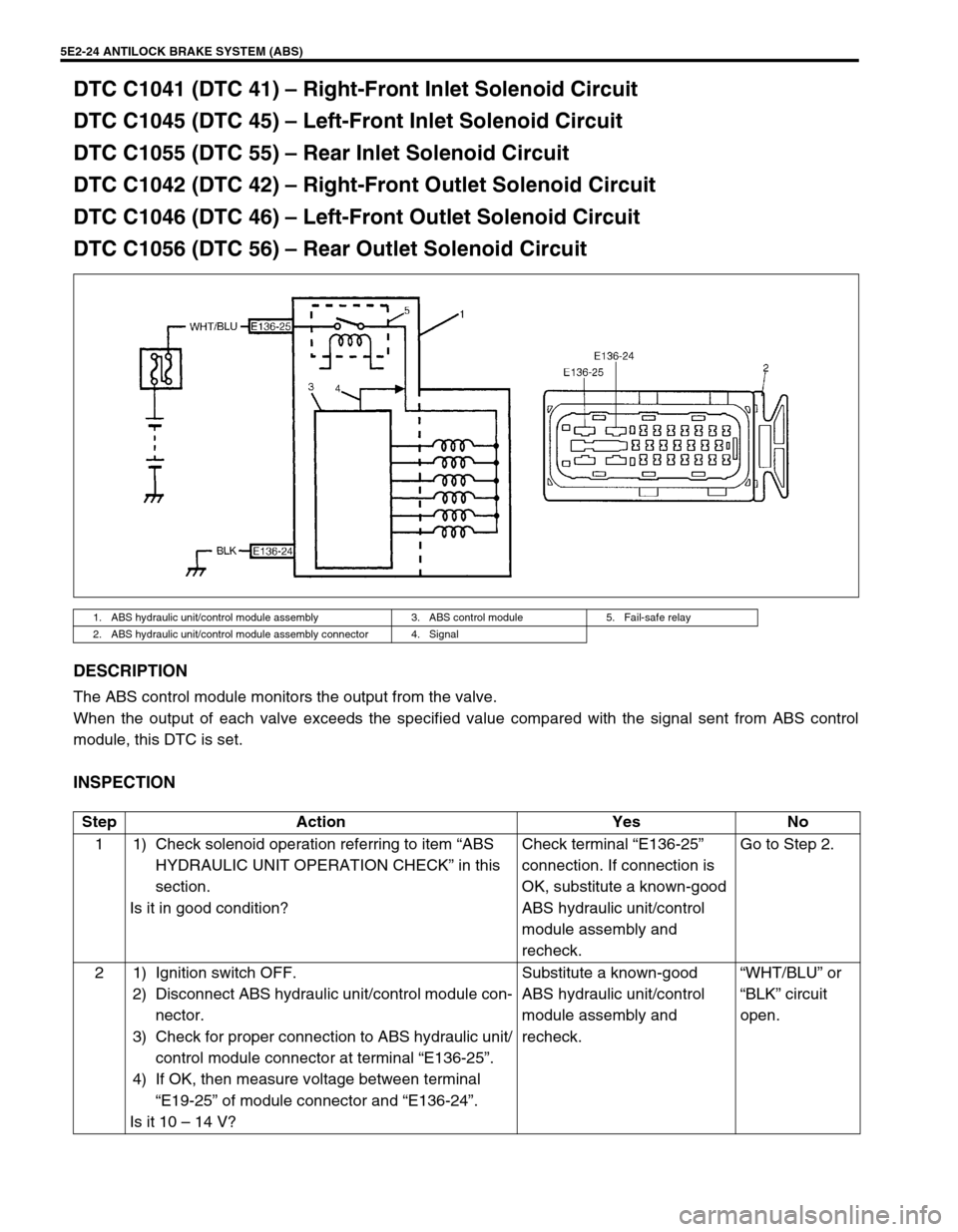
DTC C1041 (DTC 41) – Right-Front Inlet Solenoid Circuit
DTC C1045 (DTC 45) – Left-Front Inlet Solenoid Circuit
DTC C1055 (DTC 55) – Rear Inlet Solenoid Circuit
DTC C1042 (DTC 42) – Right-Front Outlet Solenoid Circuit
DTC C1046 (DTC 46) – Left-Front Outlet Solenoid Circuit
DTC C1056 (DTC 56) – Rear Outlet Solenoid Circuit
DESCRIPTION
The ABS control module monitors the output from the valve.
When the output of each valve exceeds the specified value compared with the signal sent from ABS control
module, this DTC is set.
INSPECTION
1. ABS hydraulic unit/control module assembly 3. ABS control module 5. Fail-safe relay
2. ABS hydraulic unit/control module assembly connector 4. Signal
Step Action Yes No
1 1) Check solenoid operation referring to item “ABS
HYDRAULIC UNIT OPERATION CHECK” in this
section.
Is it in good condition?Check terminal “E136-25”
connection. If connection is
OK, substitute a known-good
ABS hydraulic unit/control
module assembly and
recheck.Go to Step 2.
2 1) Ignition switch OFF.
2) Disconnect ABS hydraulic unit/control module con-
nector.
3) Check for proper connection to ABS hydraulic unit/
control module connector at terminal “E136-25”.
4) If OK, then measure voltage between terminal
“E19-25” of module connector and “E136-24”.
Is it 10 – 14 V?Substitute a known-good
ABS hydraulic unit/control
module assembly and
recheck.“WHT/BLU” or
“BLK” circuit
open.
Page 150 of 656
ANTILOCK BRAKE SYSTEM (ABS) 5E2-25
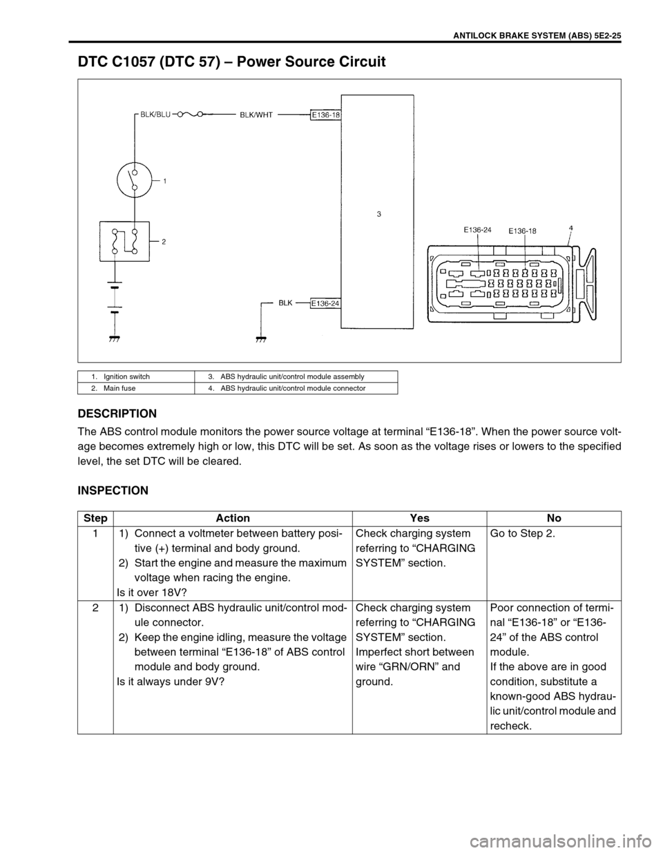
DTC C1057 (DTC 57) – Power Source Circuit
DESCRIPTION
The ABS control module monitors the power source voltage at terminal “E136-18”. When the power source volt-
age becomes extremely high or low, this DTC will be set. As soon as the voltage rises or lowers to the specified
level, the set DTC will be cleared.
INSPECTION
1. Ignition switch 3. ABS hydraulic unit/control module assembly
2. Main fuse 4. ABS hydraulic unit/control module connector
Step Action Yes No
1 1) Connect a voltmeter between battery posi-
tive (+) terminal and body ground.
2) Start the engine and measure the maximum
voltage when racing the engine.
Is it over 18V?Check charging system
referring to “CHARGING
SYSTEM” section.Go to Step 2.
2 1) Disconnect ABS hydraulic unit/control mod-
ule connector.
2) Keep the engine idling, measure the voltage
between terminal “E136-18” of ABS control
module and body ground.
Is it always under 9V?Check charging system
referring to “CHARGING
SYSTEM” section.
Imperfect short between
wire “GRN/ORN” and
ground.Poor connection of termi-
nal “E136-18” or “E136-
24” of the ABS control
module.
If the above are in good
condition, substitute a
known-good ABS hydrau-
lic unit/control module and
recheck.