SUZUKI GRAND VITARA 1999 2.G Owners Manual
GRAND VITARA 1999 2.G
SUZUKI
SUZUKI
https://www.carmanualsonline.info/img/20/7583/w960_7583-0.png
SUZUKI GRAND VITARA 1999 2.G Owners Manual
Trending: Pcm, Change oil, relay fuel, cylinder head, compression ratio, key battery, Ignitor
Page 391 of 656
6F2-8 IGNITION SYSTEM (FOR H27 ENGINE)
On-Vehicle Service
Ignition Coil Assembly (Igniter and Ignition
Coil)
REMOVAL
1) Remove ignition coil cover.
2) Disconnect ignition coil coupler.
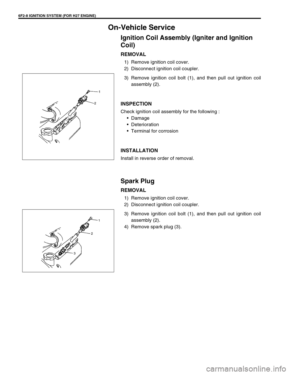
3) Remove ignition coil bolt (1), and then pull out ignition coil
assembly (2).
INSPECTION
Check ignition coil assembly for the following :
•Damage
•Deterioration
•Terminal for corrosion
INSTALLATION
Install in reverse order of removal.
Spark Plug
REMOVAL
1) Remove ignition coil cover.
2) Disconnect ignition coil coupler.
3) Remove ignition coil bolt (1), and then pull out ignition coil
assembly (2).
4) Remove spark plug (3).
Page 392 of 656
IGNITION SYSTEM (FOR H27 ENGINE) 6F2-9
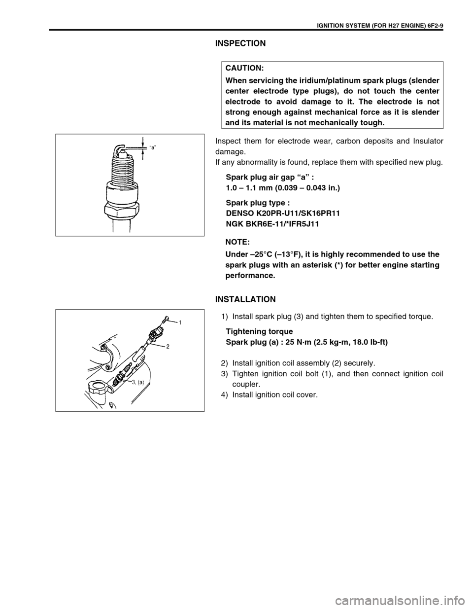
INSPECTION
Inspect them for electrode wear, carbon deposits and Insulator
damage.
If any abnormality is found, replace them with specified new plug.
Spark plug air gap “a” :
1.0 – 1.1 mm (0.039 – 0.043 in.)
Spark plug type :
DENSO K20PR-U11/SK16PR11
NGK BKR6E-11/*IFR5J11
INSTALLATION
1) Install spark plug (3) and tighten them to specified torque.
Tightening torque
Spark plug (a) : 25 N·m (2.5 kg-m, 18.0 lb-ft)
2) Install ignition coil assembly (2) securely.
3) Tighten ignition coil bolt (1), and then connect ignition coil
coupler.
4) Install ignition coil cover.CAUTION:
When servicing the iridium/platinum spark plugs (slender
center electrode type plugs), do not touch the center
electrode to avoid damage to it. The electrode is not
strong enough against mechanical force as it is slender
and its material is not mechanically tough.
NOTE:
Under –25°C (–13°F), it is highly recommended to use the
spark plugs with an asterisk (*) for better engine starting
performance.
Page 393 of 656
6F2-10 IGNITION SYSTEM (FOR H27 ENGINE)
CMP Sensor
REMOVAL
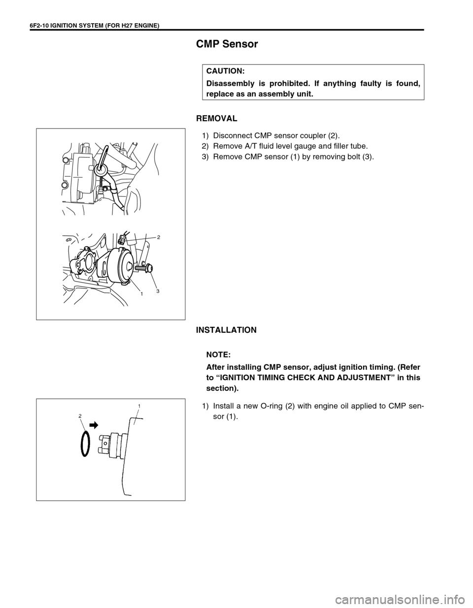
1) Disconnect CMP sensor coupler (2).
2) Remove A/T fluid level gauge and filler tube.
3) Remove CMP sensor (1) by removing bolt (3).
INSTALLATION
1) Install a new O-ring (2) with engine oil applied to CMP sen-
sor (1). CAUTION:
Disassembly is prohibited. If anything faulty is found,
replace as an assembly unit.
2
3
1
NOTE:
After installing CMP sensor, adjust ignition timing. (Refer
to “IGNITION TIMING CHECK AND ADJUSTMENT” in this
section).
Page 394 of 656
IGNITION SYSTEM (FOR H27 ENGINE) 6F2-11
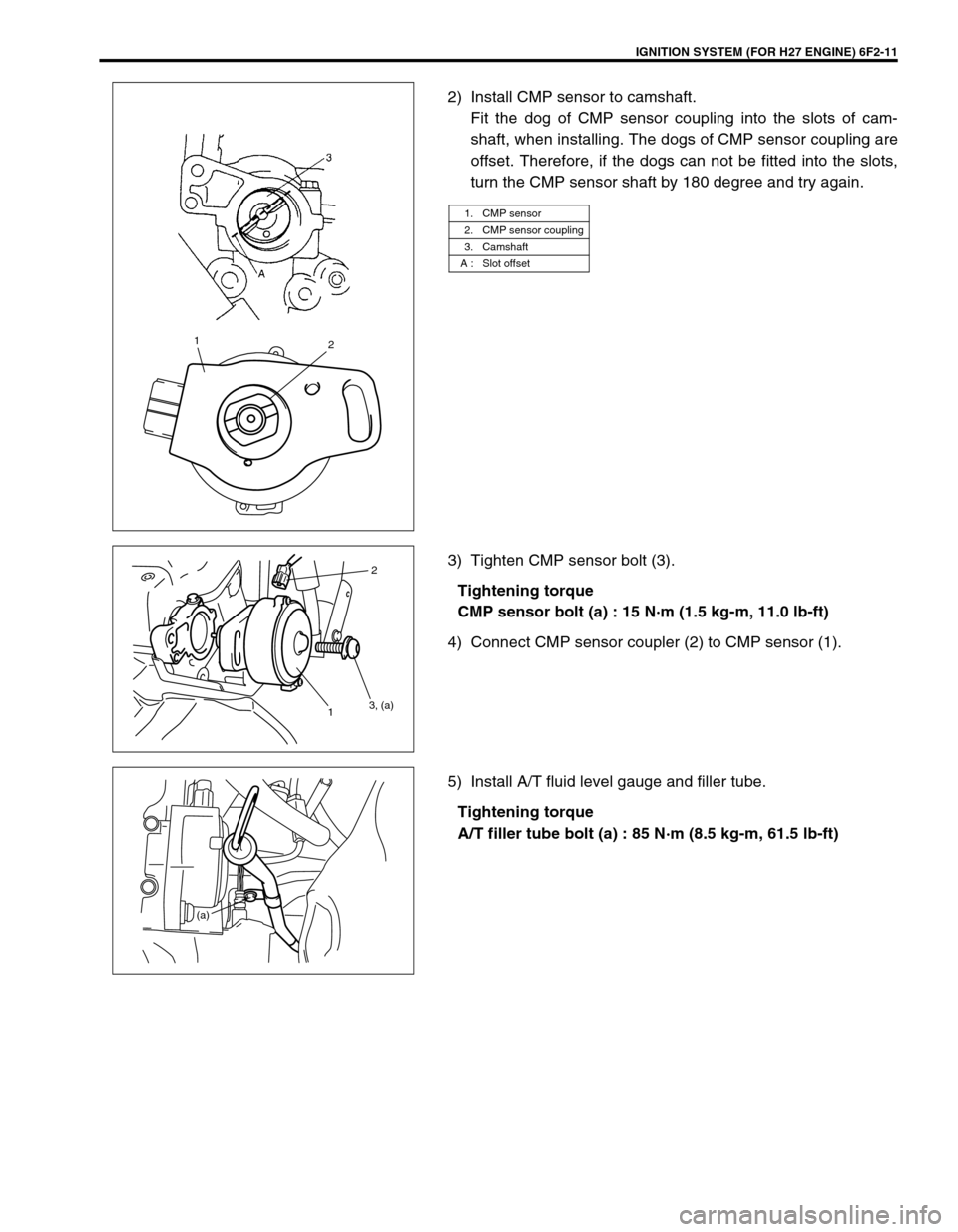
2) Install CMP sensor to camshaft.
Fit the dog of CMP sensor coupling into the slots of cam-
shaft, when installing. The dogs of CMP sensor coupling are
offset. Therefore, if the dogs can not be fitted into the slots,
turn the CMP sensor shaft by 180 degree and try again.
3) Tighten CMP sensor bolt (3).
Tightening torque
CMP sensor bolt (a) : 15 N·m (1.5 kg-m, 11.0 lb-ft)
4) Connect CMP sensor coupler (2) to CMP sensor (1).
5) Install A/T fluid level gauge and filler tube.
Tightening torque
A/T filler tube bolt (a) : 85 N·m (8.5 kg-m, 61.5 lb-ft)
1. CMP sensor
2. CMP sensor coupling
3. Camshaft
A : Slot offset
12
2
3, (a)
1
(a)
Page 395 of 656
6F2-12 IGNITION SYSTEM (FOR H27 ENGINE)
Noise Suppressor
REMOVAL
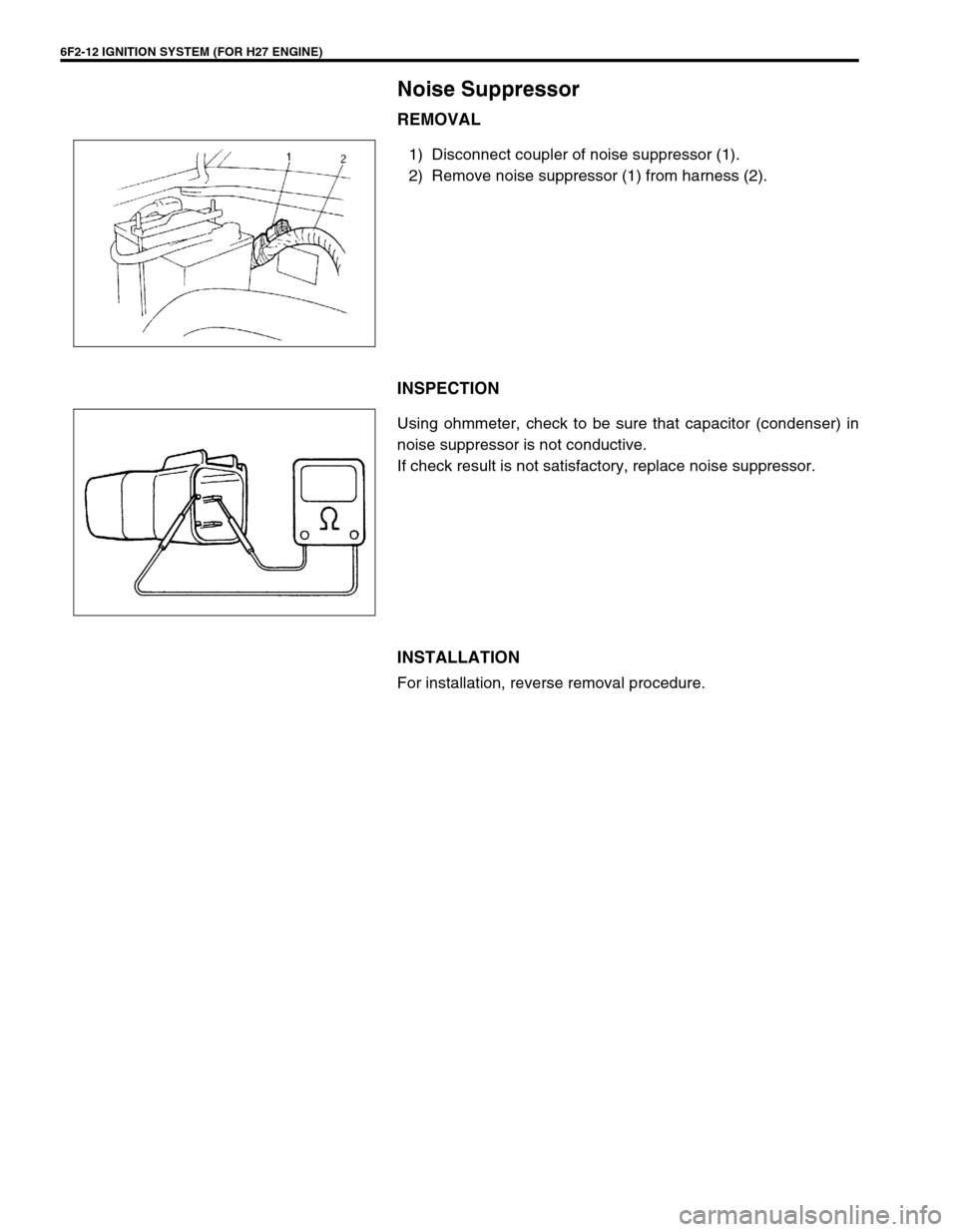
1) Disconnect coupler of noise suppressor (1).
2) Remove noise suppressor (1) from harness (2).
INSPECTION
Using ohmmeter, check to be sure that capacitor (condenser) in
noise suppressor is not conductive.
If check result is not satisfactory, replace noise suppressor.
INSTALLATION
For installation, reverse removal procedure.
Page 396 of 656
IGNITION SYSTEM (FOR H27 ENGINE) 6F2-13
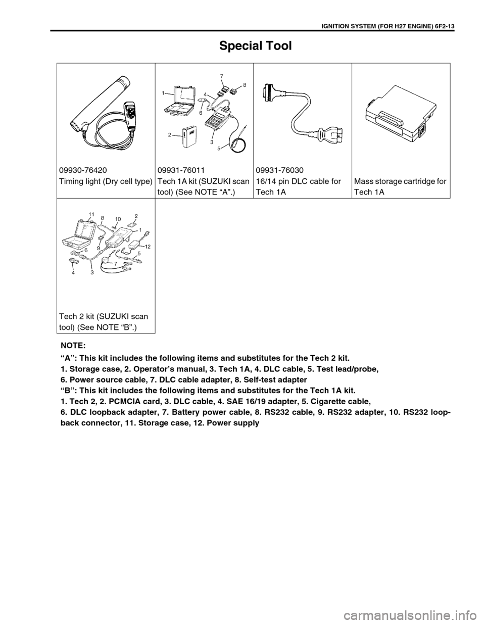
Special Tool
09930-76420 09931-76011 09931-76030
Timing light (Dry cell type) Tech 1A kit (SUZUKI scan
tool) (See NOTE “A”.)16/14 pin DLC cable for
Tech 1AMass storage cartridge for
Tech 1A
Tech 2 kit (SUZUKI scan
tool) (See NOTE “B”.)
NOTE:
“A”: This kit includes the following items and substitutes for the Tech 2 kit.
1. Storage case, 2. Operator’s manual, 3. Tech 1A, 4. DLC cable, 5. Test lead/probe,
6. Power source cable, 7. DLC cable adapter, 8. Self-test adapter
“B”: This kit includes the following items and substitutes for the Tech 1A kit.
1. Tech 2, 2. PCMCIA card, 3. DLC cable, 4. SAE 16/19 adapter, 5. Cigarette cable,
6. DLC loopback adapter, 7. Battery power cable, 8. RS232 cable, 9. RS232 adapter, 10. RS232 loop-
back connector, 11. Storage case, 12. Power supply
Page 397 of 656
6F2-14 IGNITION SYSTEM (FOR H27 ENGINE)
Page 398 of 656
CHARGING SYSTEM 6H-1
6H
SECTION 6H
CHARGING SYSTEM
CONTENTS
General Description ....................................... 6H-2
Generator ..................................................... 6H-2
Unit Repair Overhaul ..................................... 6H-3
Generator Assembly .................................... 6H-3
Inspection ................................................. 6H-3Specifications................................................. 6H-6
Battery.......................................................... 6H-6
Generator ..................................................... 6H-6
Tightening Torque Specification .................. 6H-6
WARNING:
For vehicles equipped with Supplemental Restraint (Air Bag) System:
Service on and around the air bag system components or wiring must be performed only by an
authorized SUZUKI dealer. Refer to “Air Bag System Components and Wiring Location View” under
“General Description” in Section 10B in order to confirm whether you are performing service on or
near the air bag system components or wiring. Please observe all WARNINGS and “Service Precau-
tions” under “On-Vehicle Service” in Section 10B before performing service on or around the air
bag system components or wiring. Failure to follow WARNINGS could result in unintentional activa-
tion of the system or could render the system inoperative. Either of these two conditions may result
in severe injury.
Technical service work must be started at least 90 seconds after the ignition switch is turned to the
“LOCK” position and the negative cable is disconnected from the battery. Otherwise, the system
may be activated by reserve energy in the Sensing and Diagnostic Module (SDM).
NOTE:
For the descriptions (items) not found in this section, refer to the same section of the Service Manual
mentioned in the FOREWORD of this manual.
Page 399 of 656
6H-2 CHARGING SYSTEM
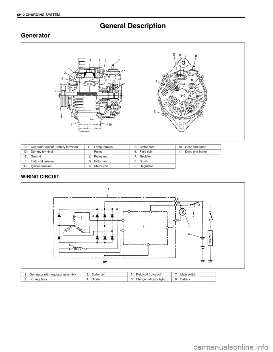
General Description
Generator
WIRING CIRCUIT
B : Generator output (Battery terminal) L : Lamp terminal 5. Stator core 10. Rear end frame
D : Dummy terminal 1. Pulley 6. Field coil 11. Drive end frame
E : Ground 2. Pulley nut 7. Rectifier
F : Field coil terminal 3. Rotor fan 8. Brush
IG : Ignition terminal 4. Stator coil 9. Regulator
1. Generator with regulator assembly 3. Stator coil 5. Field coil (rotor coil) 7. Main switch
2. I.C. regulator 4. Diode 6. Charge indicator light 8. Battery
Page 400 of 656
CHARGING SYSTEM 6H-3
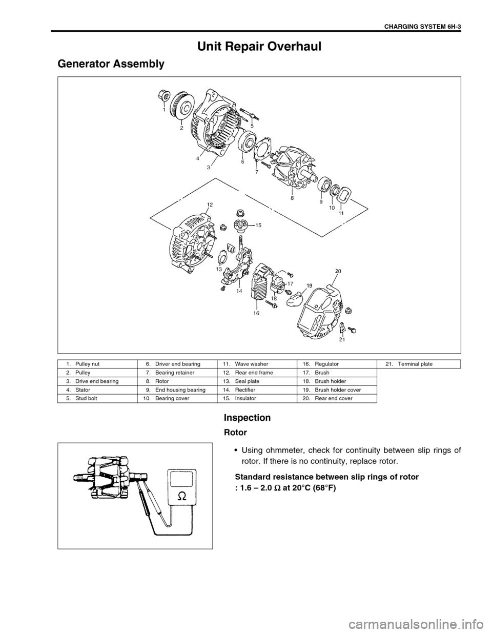
Unit Repair Overhaul
Generator Assembly
Inspection
Rotor
•Using ohmmeter, check for continuity between slip rings of
rotor. If there is no continuity, replace rotor.
Standard resistance between slip rings of rotor
: 1.6 – 2.0 Ω
ΩΩ Ω at 20°C (68°F)
1. Pulley nut 6. Driver end bearing 11. Wave washer 16. Regulator 21. Terminal plate
2. Pulley 7. Bearing retainer 12. Rear end frame 17. Brush
3. Drive end bearing 8. Rotor 13. Seal plate 18. Brush holder
4. Stator 9. End housing bearing 14. Rectifier 19. Brush holder cover
5. Stud bolt 10. Bearing cover 15. Insulator 20. Rear end cover
Trending: fuel filter, Oil gear, compressor relay, Tire pressure, width, fuel reserve, service interval
