Heat SUZUKI GRAND VITARA 2001 2.G Owner's Manual
[x] Cancel search | Manufacturer: SUZUKI, Model Year: 2001, Model line: GRAND VITARA, Model: SUZUKI GRAND VITARA 2001 2.GPages: 656, PDF Size: 14.31 MB
Page 193 of 656
6-1-32 ENGINE GENERAL INFORMATION AND DIAGNOSIS (H27 ENGINE)
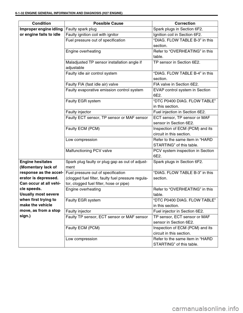
Improper engine idling
or engine fails to idleFaulty spark plug Spark plugs in Section 6F2.
Faulty ignition coil with ignitor Ignition coil in Section 6F2.
Fuel pressure out of specification “DIAG. FLOW TABLE B-3” in this
section.
Engine overheating Refer to “OVERHEATING” in this
table.
Maladjusted TP sensor installation angle if
adjustableTP sensor in Section 6E2.
Faulty idle air control system “DIAG. FLOW TABLE B-4” in this
section.
Faulty FIA (fast idle air) valve FIA valve in Section 6E2.
Faulty evaporative emission control system EVAP control system in Section
6E2.
Faulty EGR system “DTC P0400 DIAG. FLOW TABLE”
in this section.
Faulty injector Fuel injection in Section 6E2.
Faulty ECT sensor, TP sensor or MAF sensor ECT sensor, TP sensor or MAF
sensor in Section 6E2.
Faulty ECM (PCM) Inspection of ECM (PCM) and its
circuit in this section.
Low compression Refer to the same item in “HARD
STARTING” of this table.
Malfunctioning PCV valve PCV system inspection in Section
6E2.
Engine hesitates
(Momentary lack of
response as the accel-
erator is depressed.
Can occur at all vehi-
cle speeds.
Usually most severe
when first trying to
make the vehicle
move, as from a stop
sign.)Spark plug faulty or plug gap as out of adjust-
mentSpark plugs in Section 6F2.
Fuel pressure out of specification
(clogged fuel filter, faulty fuel pressure regula-
tor, clogged fuel filter, hose or pipe)“DIAG. FLOW TABLE B-3” in this
section.
Engine overheating Refer to “OVERHEATING” in this
table.
Faulty EGR system “DTC P0400 DIAG. FLOW TABLE”
in this section.
Faulty injector Fuel injector in Section 6E2.
Faulty TP sensor, ECT sensor or MAF sensor TP sensor, ECT sensor or MAF
sensor in Section 6E2.
Faulty ECM (PCM) Inspection of ECM (PCM) and its
circuit in this section.
Low compression Refer to the same item in “HARD
STARTING” of this table. Condition Possible Cause Correction
Page 194 of 656
ENGINE GENERAL INFORMATION AND DIAGNOSIS (H27 ENGINE) 6-1-33
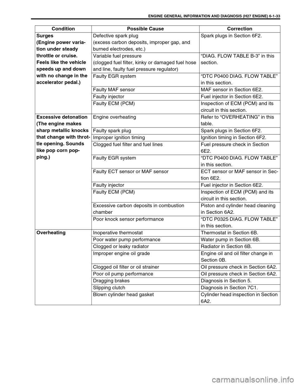
Surges
(Engine power varia-
tion under steady
throttle or cruise.
Feels like the vehicle
speeds up and down
with no change in the
accelerator pedal.)Defective spark plug
(excess carbon deposits, improper gap, and
burned electrodes, etc.)Spark plugs in Section 6F2.
Variable fuel pressure
(clogged fuel filter, kinky or damaged fuel hose
and line, faulty fuel pressure regulator)“DIAG. FLOW TABLE B-3” in this
section.
Faulty EGR system “DTC P0400 DIAG. FLOW TABLE”
in this section.
Faulty MAF sensor MAF sensor in Section 6E2.
Faulty injector Fuel injector in Section 6E2.
Faulty ECM (PCM) Inspection of ECM (PCM) and its
circuit in this section.
Excessive detonation
(The engine makes
sharp metallic knocks
that change with throt-
tle opening. Sounds
like pop corn pop-
ping.)Engine overheating Refer to “OVERHEATING” in this
table.
Faulty spark plug Spark plugs in Section 6F2.
Improper ignition timing Ignition timing in Section 6F2.
Clogged fuel filter and fuel lines Fuel pressure check in Section
6E2.
Faulty EGR system “DTC P0400 DIAG. FLOW TABLE”
in this section.
Faulty ECT sensor or MAF sensor ECT sensor or MAF sensor in Sec-
tion 6E2.
Faulty injector Fuel injector in Section 6E2.
Faulty ECM (PCM) Inspection of ECM (PCM) and its
circuit in this section.
Excessive carbon deposits in combustion
chamberPiston and cylinder head cleaning
in Section 6A2.
Poor knock sensor performance “DTC P0325 DIAG. FLOW TABLE”
in this section.
Overheating
Inoperative thermostat Thermostat in Section 6B.
Poor water pump performance Water pump in Section 6B.
Clogged or leaky radiator Radiator in Section 6B.
Improper engine oil grade Engine oil and oil filter change in
Section 0B.
Clogged oil filter or oil strainer Oil pressure check in Section 6A2.
Poor oil pump performance Oil pressure check in Section 6A2.
Dragging brakes Diagnosis in Section 5.
Slipping clutch Diagnosis in Section 7C1.
Blown cylinder head gasket Cylinder head inspection in Section
6A2. Condition Possible Cause Correction
Page 198 of 656
ENGINE GENERAL INFORMATION AND DIAGNOSIS (H27 ENGINE) 6-1-37
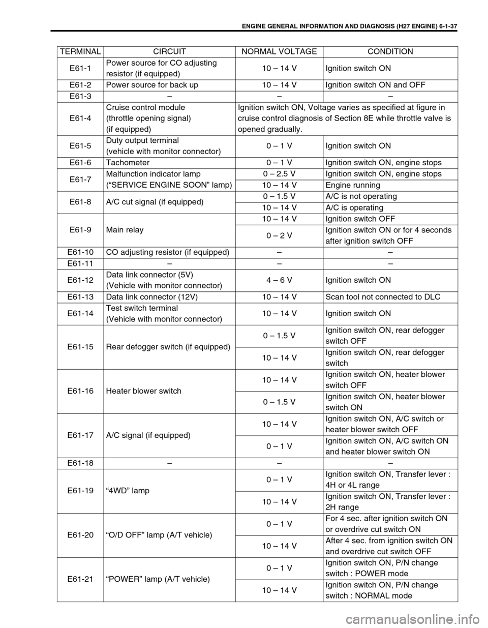
TERMINAL CIRCUIT NORMAL VOLTAGE CONDITION
E61-1Power source for CO adjusting
resistor (if equipped)10 – 14 V Ignition switch ON
E61-2 Power source for back up 10 – 14 V Ignition switch ON and OFF
E61-3 – – –
E61-4Cruise control module
(throttle opening signal)
(if equipped)Ignition switch ON, Voltage varies as specified at figure in
cruise control diagnosis of Section 8E while throttle valve is
opened gradually.
E61-5Duty output terminal
(vehicle with monitor connector)0 – 1 V Ignition switch ON
E61-6 Tachometer 0 – 1 V Ignition switch ON, engine stops
E61-7Malfunction indicator lamp
(“SERVICE ENGINE SOON” lamp)0 – 2.5 V Ignition switch ON, engine stops
10 – 14 V Engine running
E61-8 A/C cut signal (if equipped)0 – 1.5 V A/C is not operating
10 – 14 V A/C is operating
E61-9 Main relay10 – 14 V Ignition switch OFF
0 – 2 VIgnition switch ON or for 4 seconds
after ignition switch OFF
E61-10 CO adjusting resistor (if equipped) – –
E61-11 – – –
E61-12Data link connector (5V)
(Vehicle with monitor connector)4 – 6 V Ignition switch ON
E61-13 Data link connector (12V) 10 – 14 V Scan tool not connected to DLC
E61-14Test switch terminal
(Vehicle with monitor connector)10 – 14 V Ignition switch ON
E61-15 Rear defogger switch (if equipped)0 – 1.5 VIgnition switch ON, rear defogger
switch OFF
10 – 14 VIgnition switch ON, rear defogger
switch
E61-16 Heater blower switch10 – 14 VIgnition switch ON, heater blower
switch OFF
0 – 1.5 VIgnition switch ON, heater blower
switch ON
E61-17 A/C signal (if equipped)10 – 14 VIgnition switch ON, A/C switch or
heater blower switch OFF
0 – 1 VIgnition switch ON, A/C switch ON
and heater blower switch ON
E61-18 – – –
E61-19 “4WD” lamp0 – 1 VIgnition switch ON, Transfer lever :
4H or 4L range
10 – 14 VIgnition switch ON, Transfer lever :
2H range
E61-20 “O/D OFF” lamp (A/T vehicle)0 – 1 VFor 4 sec. after ignition switch ON
or overdrive cut switch ON
10 – 14 VAfter 4 sec. from ignition switch ON
and overdrive cut switch OFF
E61-21 “POWER” lamp (A/T vehicle)0 – 1 VIgnition switch ON, P/N change
switch : POWER mode
10 – 14 VIgnition switch ON, P/N change
switch : NORMAL mode
Page 200 of 656
ENGINE GENERAL INFORMATION AND DIAGNOSIS (H27 ENGINE) 6-1-39
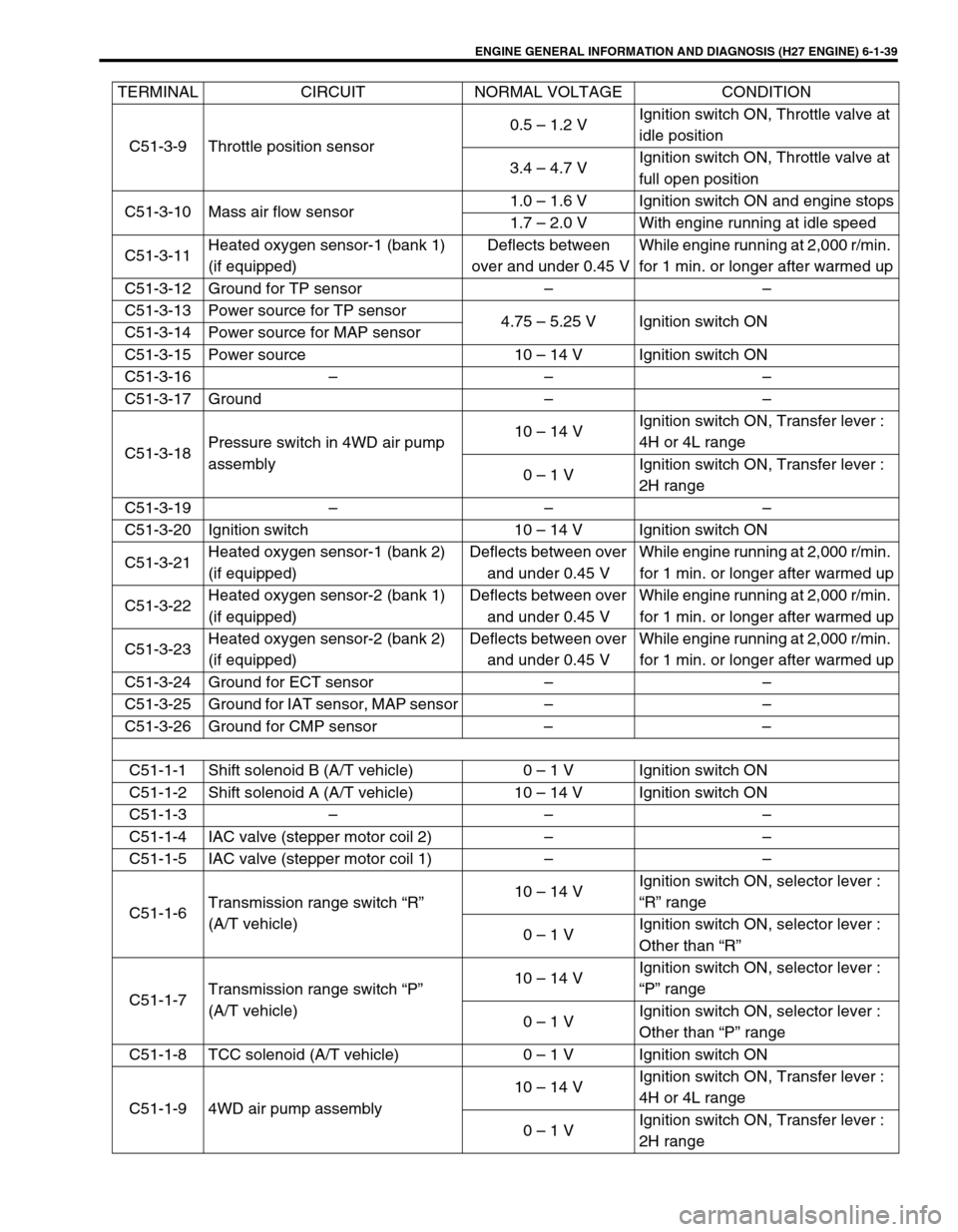
C51-3-9 Throttle position sensor0.5 – 1.2 VIgnition switch ON, Throttle valve at
idle position
3.4 – 4.7 VIgnition switch ON, Throttle valve at
full open position
C51-3-10 Mass air flow sensor1.0 – 1.6 V Ignition switch ON and engine stops
1.7 – 2.0 V With engine running at idle speed
C51-3-11Heated oxygen sensor-1 (bank 1)
(if equipped)Deflects between
over and under 0.45 VWhile engine running at 2,000 r/min.
for 1 min. or longer after warmed up
C51-3-12 Ground for TP sensor – –
C51-3-13 Power source for TP sensor
4.75 – 5.25 V Ignition switch ON
C51-3-14 Power source for MAP sensor
C51-3-15 Power source 10 – 14 V Ignition switch ON
C51-3-16 – – –
C51-3-17 Ground – –
C51-3-18Pressure switch in 4WD air pump
assembly10 – 14 VIgnition switch ON, Transfer lever :
4H or 4L range
0 – 1 VIgnition switch ON, Transfer lever :
2H range
C51-3-19 – – –
C51-3-20 Ignition switch 10 – 14 V Ignition switch ON
C51-3-21Heated oxygen sensor-1 (bank 2)
(if equipped)Deflects between over
and under 0.45 VWhile engine running at 2,000 r/min.
for 1 min. or longer after warmed up
C51-3-22Heated oxygen sensor-2 (bank 1)
(if equipped)Deflects between over
and under 0.45 VWhile engine running at 2,000 r/min.
for 1 min. or longer after warmed up
C51-3-23Heated oxygen sensor-2 (bank 2)
(if equipped)Deflects between over
and under 0.45 VWhile engine running at 2,000 r/min.
for 1 min. or longer after warmed up
C51-3-24 Ground for ECT sensor – –
C51-3-25 Ground for IAT sensor, MAP sensor – –
C51-3-26 Ground for CMP sensor – –
C51-1-1 Shift solenoid B (A/T vehicle) 0 – 1 V Ignition switch ON
C51-1-2 Shift solenoid A (A/T vehicle) 10 – 14 V Ignition switch ON
C51-1-3 – – –
C51-1-4 IAC valve (stepper motor coil 2) – –
C51-1-5 IAC valve (stepper motor coil 1) – –
C51-1-6Transmission range switch “R”
(A/T vehicle)10 – 14 VIgnition switch ON, selector lever :
“R” range
0 – 1 VIgnition switch ON, selector lever :
Other than “R”
C51-1-7Transmission range switch “P”
(A/T vehicle)10 – 14 VIgnition switch ON, selector lever :
“P” range
0 – 1 VIgnition switch ON, selector lever :
Other than “P” range
C51-1-8 TCC solenoid (A/T vehicle) 0 – 1 V Ignition switch ON
C51-1-9 4WD air pump assembly10 – 14 VIgnition switch ON, Transfer lever :
4H or 4L range
0 – 1 VIgnition switch ON, Transfer lever :
2H range TERMINAL CIRCUIT NORMAL VOLTAGE CONDITION
Page 202 of 656
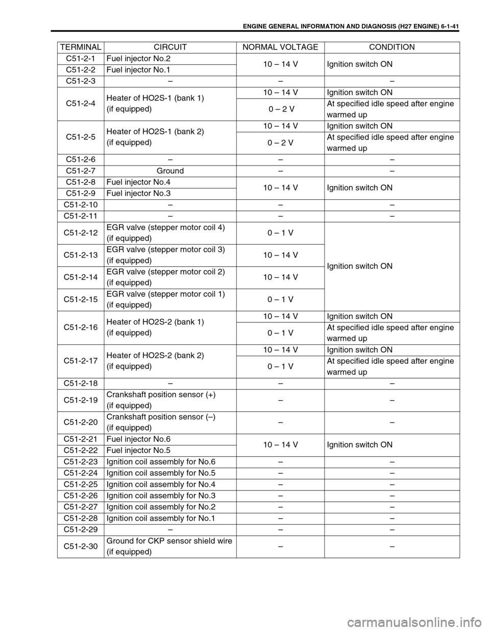
ENGINE GENERAL INFORMATION AND DIAGNOSIS (H27 ENGINE) 6-1-41
C51-2-1 Fuel injector No.2
10 – 14 V Ignition switch ON
C51-2-2 Fuel injector No.1
C51-2-3 – – –
C51-2-4Heater of HO2S-1 (bank 1)
(if equipped)10 – 14 V Ignition switch ON
0 – 2 VAt specified idle speed after engine
warmed up
C51-2-5Heater of HO2S-1 (bank 2)
(if equipped)10 – 14 V Ignition switch ON
0 – 2 VAt specified idle speed after engine
warmed up
C51-2-6 – – –
C51-2-7 Ground – –
C51-2-8 Fuel injector No.4
10 – 14 V Ignition switch ON
C51-2-9 Fuel injector No.3
C51-2-10 – – –
C51-2-11 – – –
C51-2-12EGR valve (stepper motor coil 4)
(if equipped)0 – 1 V
Ignition switch ON C51-2-13EGR valve (stepper motor coil 3)
(if equipped)10 – 14 V
C51-2-14EGR valve (stepper motor coil 2)
(if equipped)10 – 14 V
C51-2-15EGR valve (stepper motor coil 1)
(if equipped)0 – 1 V
C51-2-16Heater of HO2S-2 (bank 1)
(if equipped)10 – 14 V Ignition switch ON
0 – 1 VAt specified idle speed after engine
warmed up
C51-2-17Heater of HO2S-2 (bank 2)
(if equipped)10 – 14 V Ignition switch ON
0 – 1 VAt specified idle speed after engine
warmed up
C51-2-18 – – –
C51-2-19Crankshaft position sensor (+)
(if equipped)––
C51-2-20Crankshaft position sensor (–)
(if equipped)––
C51-2-21 Fuel injector No.6
10 – 14 V Ignition switch ON
C51-2-22 Fuel injector No.5
C51-2-23 Ignition coil assembly for No.6 – –
C51-2-24 Ignition coil assembly for No.5 – –
C51-2-25 Ignition coil assembly for No.4 – –
C51-2-26 Ignition coil assembly for No.3 – –
C51-2-27 Ignition coil assembly for No.2 – –
C51-2-28 Ignition coil assembly for No.1 – –
C51-2-29 – – –
C51-2-30Ground for CKP sensor shield wire
(if equipped)–– TERMINAL CIRCUIT NORMAL VOLTAGE CONDITION
Page 203 of 656
6-1-42 ENGINE GENERAL INFORMATION AND DIAGNOSIS (H27 ENGINE)
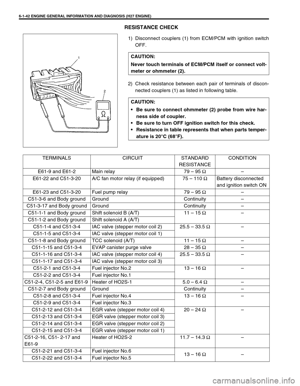
RESISTANCE CHECK
1) Disconnect couplers (1) from ECM/PCM with ignition switch
OFF.
2) Check resistance between each pair of terminals of discon-
nected couplers (1) as listed in following table. CAUTION:
Never touch terminals of ECM/PCM itself or connect volt-
meter or ohmmeter (2).
CAUTION:
Be sure to connect ohmmeter (2) probe from wire har-
ness side of coupler.
Be sure to turn OFF ignition switch for this check.
Resistance in table represents that when parts temper-
ature is 20°C (68°F).
TERMINALS CIRCUIT STANDARD
RESISTANCECONDITION
E61-9 and E61-2 Main relay 79 – 95 Ω–
E61-22 and C51-3-20 A/C fan motor relay (if equipped) 75 – 110 ΩBattery disconnected
and ignition switch ON
E61-23 and C51-3-20 Fuel pump relay 79 – 95 Ω–
C51-3-6 and Body ground Ground Continuity –
C51-3-17 and Body ground Ground Continuity –
C51-1-1 and Body ground Shift solenoid B (A/T) 11 – 15 Ω–
C51-1-2 and Body ground Shift solenoid A (A/T)
C51-1-4 and C51-3-4 IAC valve (stepper motor coil 2) 25.5 – 33.5 Ω–
C51-1-5 and C51-3-4 IAC valve (stepper motor coil 1)
C51-1-8 and Body ground TCC solenoid (A/T) 11 – 15 Ω–
C51-1-15 and C51-3-4 EVAP canister purge valve 28 – 35 Ω–
C51-1-16 and C51-3-4 IAC valve (stepper motor coil 4) 25.5 – 33.5 Ω–
C51-1-17 and C51-3-4 IAC valve (stepper motor coil 3)
C51-2-1 and C51-3-4 Fuel injector No.2 13 – 16 Ω–
C51-2-2 and C51-3-4 Fuel injector No.1
C51-2-4, C51-2-5 and E61-9 Heater of HO2S-1 5.0 – 6.4 Ω–
C51-2-7 and Body ground Ground Continuity –
C51-2-8 and C51-3-4 Fuel injector No.4 13 – 16 Ω–
C51-2-9 and C51-3-4 Fuel injector No.3
C51-2-12 and C51-3-4 EGR valve (stepper motor coil 4) 20 – 24 Ω–
C51-2-13 and C51-3-4 EGR valve (stepper motor coil 3)
C51-2-14 and C51-3-4 EGR valve (stepper motor coil 2)
C51-2-15 and C51-3-4 EGR valve (stepper motor coil 1)
C51-2-16, C51- 2-17 and
E61-9Heater of HO2S-2 11.7 – 14.3 Ω–
C51-2-21 and C51-3-4 Fuel injector No.6
13 – 16 Ω–
C51-2-22 and C51-3-4 Fuel injector No.5
Page 219 of 656
6-1-58 ENGINE GENERAL INFORMATION AND DIAGNOSIS (H27 ENGINE)
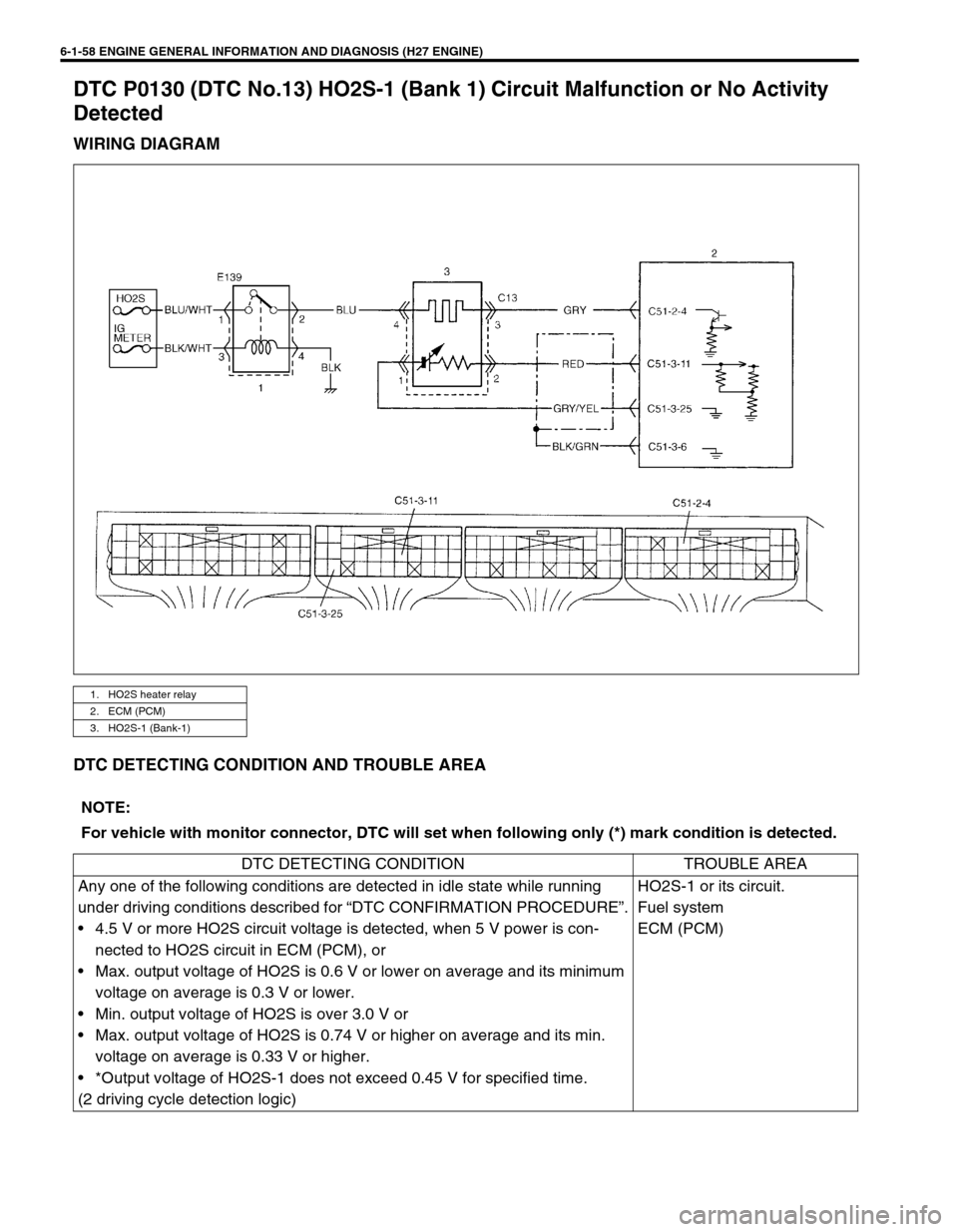
DTC P0130 (DTC No.13) HO2S-1 (Bank 1) Circuit Malfunction or No Activity
Detected
WIRING DIAGRAM
DTC DETECTING CONDITION AND TROUBLE AREA
1. HO2S heater relay
2. ECM (PCM)
3. HO2S-1 (Bank-1)
NOTE:
For vehicle with monitor connector, DTC will set when following only (*) mark condition is detected.
DTC DETECTING CONDITION TROUBLE AREA
Any one of the following conditions are detected in idle state while running
under driving conditions described for “DTC CONFIRMATION PROCEDURE”.
• 4.5 V or more HO2S circuit voltage is detected, when 5 V power is con-
nected to HO2S circuit in ECM (PCM), or
• Max. output voltage of HO2S is 0.6 V or lower on average and its minimum
voltage on average is 0.3 V or lower.
• Min. output voltage of HO2S is over 3.0 V or
• Max. output voltage of HO2S is 0.74 V or higher on average and its min.
voltage on average is 0.33 V or higher.
• *Output voltage of HO2S-1 does not exceed 0.45 V for specified time.
(2 driving cycle detection logic)HO2S-1 or its circuit.
Fuel system
ECM (PCM)
Page 222 of 656
ENGINE GENERAL INFORMATION AND DIAGNOSIS (H27 ENGINE) 6-1-61
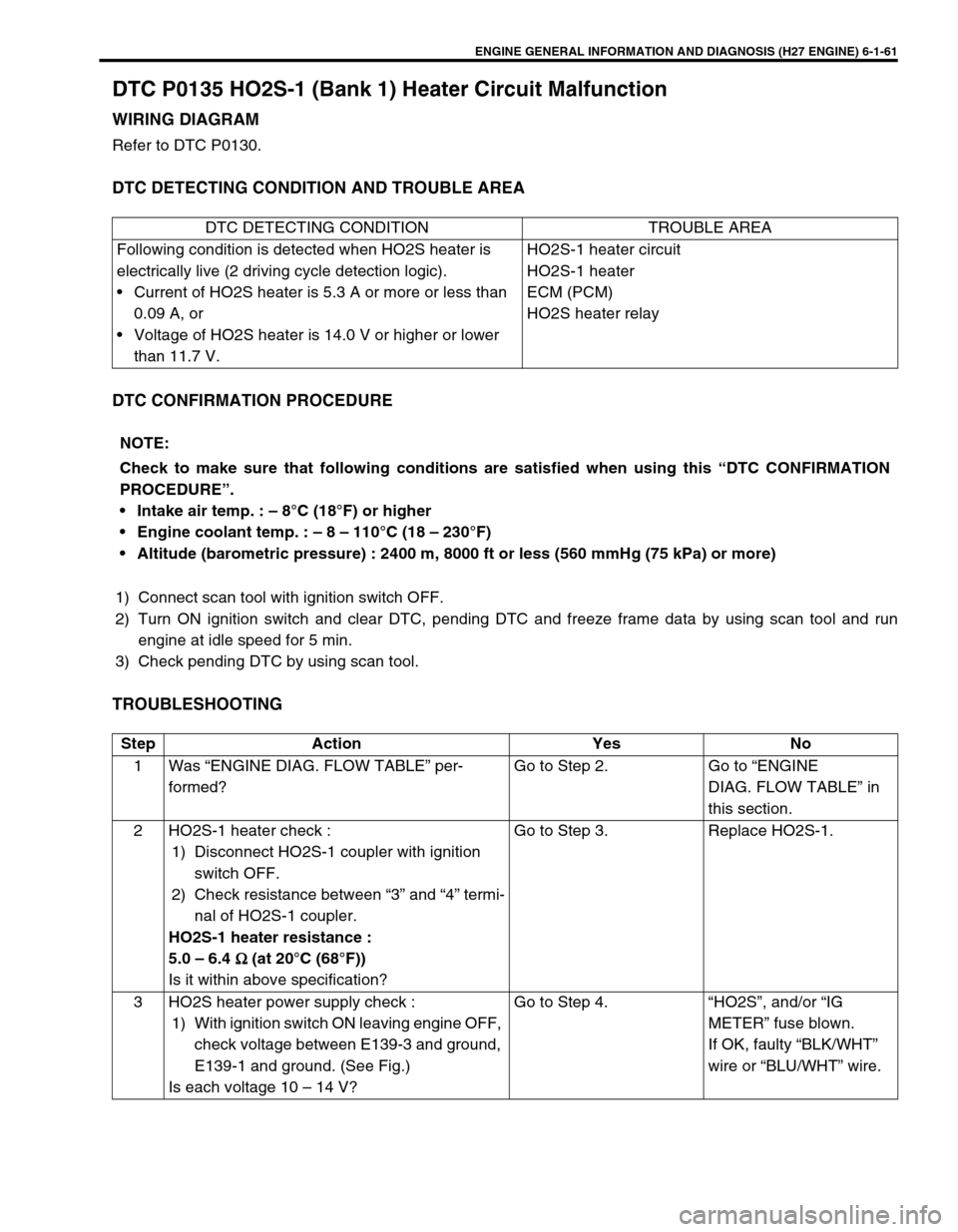
DTC P0135 HO2S-1 (Bank 1) Heater Circuit Malfunction
WIRING DIAGRAM
Refer to DTC P0130.
DTC DETECTING CONDITION AND TROUBLE AREA
DTC CONFIRMATION PROCEDURE
1) Connect scan tool with ignition switch OFF.
2) Turn ON ignition switch and clear DTC, pending DTC and freeze frame data by using scan tool and run
engine at idle speed for 5 min.
3) Check pending DTC by using scan tool.
TROUBLESHOOTING
DTC DETECTING CONDITION TROUBLE AREA
Following condition is detected when HO2S heater is
electrically live (2 driving cycle detection logic).
• Current of HO2S heater is 5.3 A or more or less than
0.09 A, or
• Voltage of HO2S heater is 14.0 V or higher or lower
than 11.7 V.HO2S-1 heater circuit
HO2S-1 heater
ECM (PCM)
HO2S heater relay
NOTE:
Check to make sure that following conditions are satisfied when using this “DTC CONFIRMATION
PROCEDURE”.
Intake air temp. : – 8°C (18°F) or higher
Engine coolant temp. : – 8 – 110°C (18 – 230°F)
Altitude (barometric pressure) : 2400 m, 8000 ft or less (560 mmHg (75 kPa) or more)
Step Action Yes No
1 Was “ENGINE DIAG. FLOW TABLE” per-
formed?Go to Step 2. Go to “ENGINE
DIAG. FLOW TABLE” in
this section.
2 HO2S-1 heater check :
1) Disconnect HO2S-1 coupler with ignition
switch OFF.
2) Check resistance between “3” and “4” termi-
nal of HO2S-1 coupler.
HO2S-1 heater resistance :
5.0 – 6.4
Ω
ΩΩ Ω (at 20°C (68°F))
Is it within above specification?Go to Step 3. Replace HO2S-1.
3 HO2S heater power supply check :
1) With ignition switch ON leaving engine OFF,
check voltage between E139-3 and ground,
E139-1 and ground. (See Fig.)
Is each voltage 10 – 14 V?Go to Step 4. “HO2S”, and/or “IG
METER” fuse blown.
If OK, faulty “BLK/WHT”
wire or “BLU/WHT” wire.
Page 223 of 656

6-1-62 ENGINE GENERAL INFORMATION AND DIAGNOSIS (H27 ENGINE)
Fig. for STEP 34 HO2S heater control circuit check :
1) With ignition switch OFF, install HO2S
heater relay.
2) With ignition switch ON leaving engine OFF,
check voltage between C51-2-4 and
ground.
Is the voltage 10 – 14 V?Substitute a known-good
ECM (PCM) and recheck.Faulty HO2S heater relay
or “BLK” wire open, “BLU”
wire open or shorted to
ground circuit
or
“GRY” wire open or
shorted to ground circuit.
If OK, substitute a known-
good ECM (PCM) and
recheck. Step Action Yes No
a. HO2S heater relay
Page 224 of 656
ENGINE GENERAL INFORMATION AND DIAGNOSIS (H27 ENGINE) 6-1-63
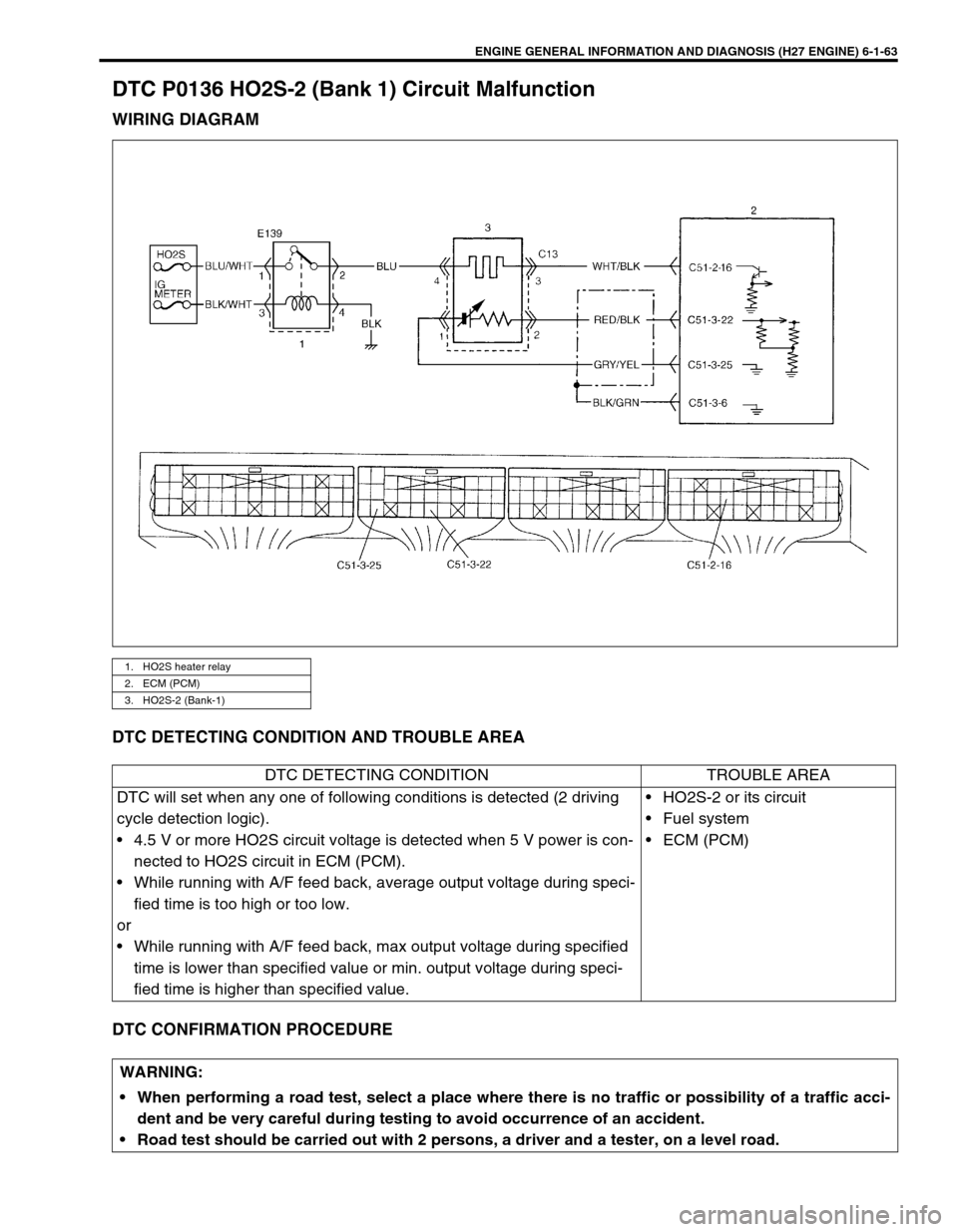
DTC P0136 HO2S-2 (Bank 1) Circuit Malfunction
WIRING DIAGRAM
DTC DETECTING CONDITION AND TROUBLE AREA
DTC CONFIRMATION PROCEDURE
1. HO2S heater relay
2. ECM (PCM)
3. HO2S-2 (Bank-1)
DTC DETECTING CONDITION TROUBLE AREA
DTC will set when any one of following conditions is detected (2 driving
cycle detection logic).
• 4.5 V or more HO2S circuit voltage is detected when 5 V power is con-
nected to HO2S circuit in ECM (PCM).
• While running with A/F feed back, average output voltage during speci-
fied time is too high or too low.
or
• While running with A/F feed back, max output voltage during specified
time is lower than specified value or min. output voltage during speci-
fied time is higher than specified value.• HO2S-2 or its circuit
• Fuel system
•ECM (PCM)
WARNING:
When performing a road test, select a place where there is no traffic or possibility of a traffic acci-
dent and be very careful during testing to avoid occurrence of an accident.
Road test should be carried out with 2 persons, a driver and a tester, on a level road.