jacking SUZUKI GRAND VITARA 2007 3.G Owners Manual
[x] Cancel search | Manufacturer: SUZUKI, Model Year: 2007, Model line: GRAND VITARA, Model: SUZUKI GRAND VITARA 2007 3.GPages: 211, PDF Size: 3.21 MB
Page 7 of 211

Downloaded from www.Manualslib.com manuals search engine 66J21-03E
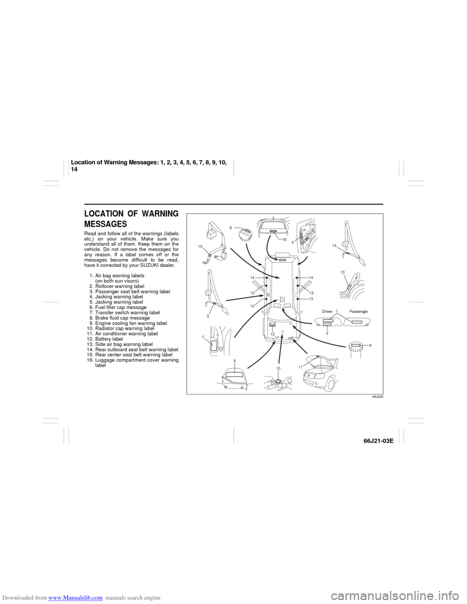
LOCATION OF WARNING
MESSAGESRead and follow all of the warnings (labels
etc.) on your vehicle. Make sure you
understand all of them. Keep them on the
vehicle. Do not remove the messages for
any reason. If a label comes off or the
messages become difficult to be read,
have it corrected by your SUZUKI dealer.
1. Air bag warning labels
(on both sun visors)
2. Rollover warning label
3. Passenger seat belt warning label
4. Jacking warning label
5. Jacking warning label
6. Fuel filler cap message
7. Transfer switch warning label
8. Brake fluid cap message
9. Engine cooling fan warning label
10. Radiator cap warning label
11. Air conditioner warning label
12. Battery label
13. Side air bag warning label
14. Rear outboard seat belt warning label
15. Rear center seat belt warning label
16. Luggage compartment cover warning
label
66J226
1
2
3
6
8 12
13 4 16
14
15
14
7
9
11
10
1413
13 1313
Driver Passenger
Location of Warning Messages: 1, 2, 3, 4, 5, 6, 7, 8, 9, 10,
14
Page 66 of 211

Downloaded from www.Manualslib.com manuals search engine 4-4 INSTRUMENT PANEL
66J21-03E
inflation pressure as specified in the vehi-
cle placard and owner’s manual.
The low tire pressure warning light is also
used to inform you of a TPMS malfunction.
When the system detects a malfunction,
this light will flash for approximately one
minute and then remain continuously illu-
minated. This sequence will be repeated
approximately ten minutes after subse-
quent vehicle start-ups as long as the mal-
function exists.
NOTE:
The low tire pressure warning light may not
come on immediately if you have a sudden
loss of air pressure.
Refer to “Tire Pressure Monitoring System”
in the “OPERATING YOUR VEHICLE”
section for additional details on the tire
pressure monitoring system. Refer to
“Tires” in the “INSPECTION AND MAIN-
TENANCE” section for information on
maintaining proper tire pressure.
WARNING
If the low tire pressure warning light
does not come on when the ignition
is turned to the “ON” position, or
comes on and blinks while driving
there may be a problem with the tire
pressure monitoring system. Have
your vehicle inspected by an autho-
rized SUZUKI dealer. Even if the light
turns off after blinking, indicating
that the monitoring system has
recovered, make sure to have an
authorized SUZUKI dealer check the
system.
WARNING
The load rating of your tires is
reduced at lower inflation pressures.
If your tires become even moderately
under-inflated, the vehicle load may
exceed the load rating of the tires,
which can lead to tire failure. The low
tire pressure warning light will not
alert you of this condition. The warn-
ing light will only come on when one
or more of your tires become signifi-
cantly under-inflated. Check and
adjust your tire inflation pressure at
least once a month. Refer to “Tires”
in the “INSPECTION AND MAINTE-
NANCE” section.
WARNING
If the low tire pressure warning light
comes on and stays on, reduce your
speed and avoid abrupt steering and
braking. Stop in a safe place as soon
as possible and check your tires.
If you have a flat tire, replace it with
the spare tire. Refer to “Jacking
Instructions” in the “EMERGENCY
SERVICE” section. Refer to
“Replacing Tires and/or Wheels”
for instructions on how to restore
normal operation of the tire pres-
sure monitoring system after you
have had a flat tire.
(Continued)
WARNING
(Continued)
If one or more of your tires is
under-inflated, adjust the inflation
pressure in all of your tires to the
recommended inflation pressure as
soon as possible.
Be aware that driving on a signifi-
cantly under-inflated tire can cause
the tire to overheat and can lead to
tire failure, and may affect steering
control and brake effectiveness. This
could lead to an accident, resulting in
severe injury or death.
Warning and Indicator Lights: 8
Page 168 of 211

Downloaded from www.Manualslib.com manuals search engine 9-30 INSPECTION AND MAINTENANCE
66J21-03E
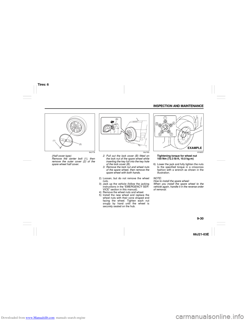
64J179
(Half cover type)
Remove the center bolt (1), then
remove the outer cover (2) of the
spare wheel half cover.
64J180
2. Pull out the lock cover (B) fitted on
the lock nut of the spare wheel while
inserting the key full into the key hole
of the lock cover (B).
3. Remove the lock nut and wheel nuts
of the spare wheel, then remove the
spare wheel with both hands.
2) Loosen, but do not remove the wheel
nuts.
3) Jack up the vehicle (follow the jacking
instructions in the “EMERGENCY SER-
VICE” section in this manual).
4) Remove the wheel nuts and wheel.
5) Install the new wheel and replace the
wheel nuts with their cone shaped end
facing the wheel. Tighten each nut
snugly by hand until the wheel is
securely seated on the hub.
81A057
Tightening torque for wheel nut
100 Nm (72.3 lb-ft, 10.0 kg-m)
6) Lower the jack and fully tighten the nuts
to the specified torque in a crisscross
fashion with a wrench as shown in the
illustration.
NOTE:
How to install the spare wheel:
When you install the spare wheel to the
vehicle again, handle it in the reverse order
of removal.
(2) (1)
(B)
EXAMPLE
Tires: 6
Page 208 of 211

Downloaded from www.Manualslib.com manuals search engine 15-3 INDEX
66J21-03E
If You Can Not Shift Automatic Transmission Gearshift
Lever Out of “P” (PARK)
.....................................................10-6
If Your Vehicle Gets Stuck ..................................................7-4
Ignition Key Reminder
........................................................2-1
Ignition Switch
.....................................................................3-1
Illumination Indicator Light
................................................4-10
Important Vehicle Design Features To Know
...................7-1
Improving Fuel Economy
....................................................6-26
Information Display
.............................................................4-17
Inside Rearview Mirror ........................................................2-16
Installation with Lap-Shoulder Seat Belts
(Child Restraint with No Top Strap)
...................................2-29
Installation with the LATCH System ..................................2-31
Installation-Child Restraint with Top Strap
.......................2-34
Instrument Cluster
...............................................................4-2
Instrument Panel
.................................................................4-1
Interior Light Switch ............................................................5-7
JJacking Instructions
............................................................10-1
Jump Starting Instructions
.................................................10-3
KKeyless Entry System Transmitter (Type B)
.....................2-10
Keyless Start System Indicator Light
................................4-9
Keyless Start System Remote Controller (Type A)
..........2-3
Keyless Start System Remote Controller/
Keyless Entry System Transmitter
....................................2-3
Keys
......................................................................................2-1
LLap-Shoulder Belt
................................................................2-22
Lighting Operation ..............................................................3-6
Lighting/Turn Signal Control Lever
...................................3-5Lights “On” reminder
......................................................... 3-7
Listening to a CD
................................................................ 4-36
Listening to a CD from an External CD Changer
(Option)
................................................................................ 4-47
Listening to a XM Satellite Radio (Option)
....................... 4-44
Listening to Audio for AUX (Option)
................................. 4-46
Listening to the Radio
........................................................ 4-34
Low Fuel Warning Light ..................................................... 4-9
Low Tire Pressure Warning Light
...............................4-3
, 6-21
Luggage Compartment Cover
........................................... 5-20
Luggage Compartment Light ............................................. 5-9
Luggage Restraint Loops
................................................... 5-19
MMaintenance Recommended under Severe Driving
Conditions
........................................................................... 9-7
Maintenance Schedule
....................................................... 9-2
Malfunction Indicator Light
................................................ 4-8
Manual Transmission
......................................................... 6-7
Mirrors
.................................................................................. 2-16
NNational Highway Traffic Safety Administration
(NHTSA)
............................................................................... 12-4
OOdometer
............................................................................. 4-11
Off-Road Driving
................................................................. 7-4
Oil Level Check ................................................................... 9-10
Oil Pressure Light ............................................................... 4-7
On-Board Vehicle Computers and Event Data
Recorders
............................................................................ 12-3
On-Pavement Driving
......................................................... 7-2
Open Door Warning Light
.................................................. 4-9