deactivate SUZUKI IGNIS 2017 User Guide
[x] Cancel search | Manufacturer: SUZUKI, Model Year: 2017, Model line: IGNIS, Model: SUZUKI IGNIS 2017Pages: 505, PDF Size: 8.36 MB
Page 196 of 505
3-43OPERATING YOUR VEHICLE
75RM4-01E
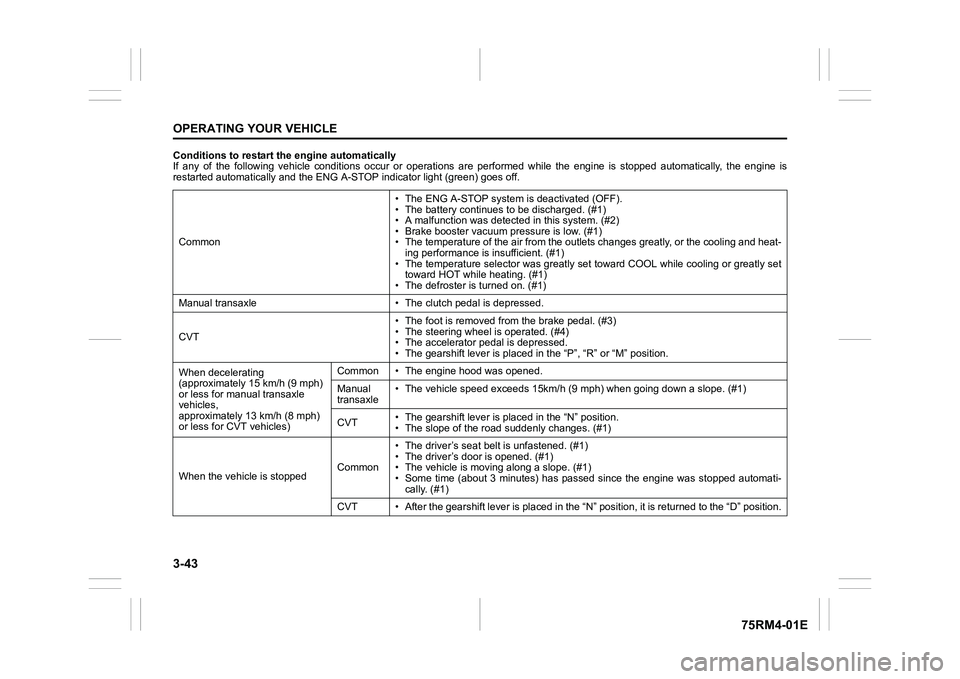
Conditions to restart the engine automatically
If any of the following vehicle conditions occur or operations are performed while the engine is stopped automatically, the en gine is
restarted automatically and the ENG A-STOP i ndicator light (green) goes off.
Common • The ENG A-STOP system is deactivated (OFF).
• The battery continues to be discharged. (#1)
• A malfunction was detect
ed in this system. (#2)
• Brake booster vacuum pressure is low. (#1)
• The temperature of the air from the outlets changes greatly, o r the cooling and heat-
ing performance is insufficient. (#1)
• The temperature selector was greatly set toward COOL while coo ling or greatly set
toward HOT while heating. (#1)
• The defroster is turned on. (#1)
Manual transaxle • The cl utch pedal is depressed.
CVT • The foot is removed from the brake pedal. (#3)
• The steering wheel is operated. (#4)
• The accelerator pedal is depressed.
• The gearshift lever is placed
in the “P”, “R” or “M” position.
When decelerating
(approximately 15 km/h (9 mph)
or less for manual transaxle
vehicles,
approximately 13 km/h (8 mph)
or less for CVT vehicles) Common • The engine hood was opened.
Manual
transaxle
• The vehicle speed exceeds 15km/
h (9 mph) when going down a slope. (#1)
CVT • The gearshift lever is placed in the “N” position.
• The slope of the road
suddenly changes. (#1)
When the vehicle is stopped Common• The driver’s seat
belt is unfastened. (#1)
• The driver’s door is opened. (#1)
• The vehicle is movi ng along a slope. (#1)
• Some time (about 3 minutes) has passed since the engine was st opped automati-
cally. (#1)
CVT • After the gearshift lever is placed in the “N” position, it is returned to the “D” position.
Page 198 of 505
3-45OPERATING YOUR VEHICLE
75RM4-01E
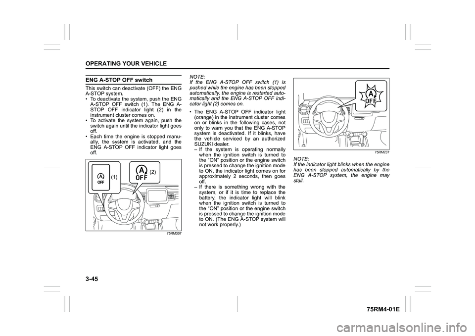
ENG A-STOP OFF switchThis switch can deactivate (OFF) the ENG
A-STOP system.
• To deactivate the system, push the ENGA-STOP OFF switch (1). The ENG A-
STOP OFF indicator light (2) in the
instrument cluster comes on.
• To activate the system again, push the switch again until the indicator light goes
off.
• Each time the engine is stopped manu- ally, the system is activated, and the
ENG A-STOP OFF indicator light goes
off.
75RM307
NOTE:
If the ENG A-STOP OFF switch (1) is
pushed while the engine has been stopped
automatically, the engine is restarted auto-
matically and the ENG A-STOP OFF indi-
cator light (2) comes on.
• The ENG A-STOP OFF indicator light (orange) in the instrument cluster comes
on or blinks in the following cases, not
only to warn you that the ENG A-STOP
system is deactivated. If it blinks, have
the vehicle serviced by an authorized
SUZUKI dealer.
– If the system is operating normally
when the ignition switch is turned to
the “ON” position or the engine switch
is pressed to change the ignition mode
to ON, the indicator light comes on for
approximately 2 seconds, then goes
off.
– If there is something wrong with the system, or if it is time to replace the
battery, the indicator light will blink
when the ignition switch is turned to
the “ON” position or the engine switch
is pressed to change the ignition mode
to ON. (The ENG A-STOP system will
not work properly.)
75RM237
NOTE:
If the indicator light blinks when the engine
has been stopped automatically by the
ENG A-STOP system, the engine may
stall.
(2)
(1)
Page 224 of 505
3-71OPERATING YOUR VEHICLE
75RM4-01E
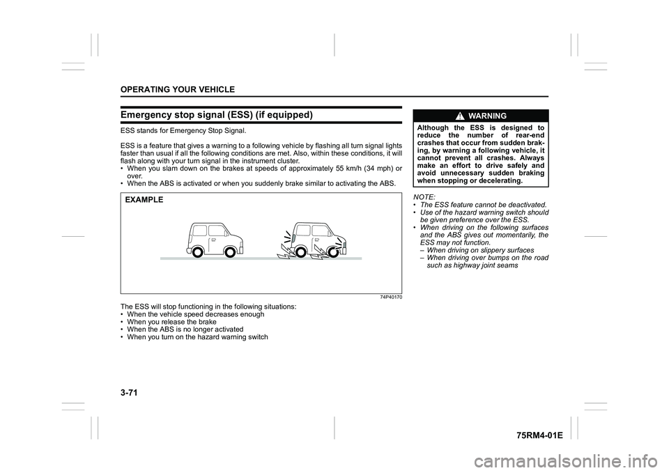
Emergency stop signal (ESS) (if equipped)ESS stands for Emergency Stop Signal.
ESS is a feature that gives a war ning to a following vehicle by flashing all turn signal lights
faster than usual if all the following conditions are met. Also , within these conditions, it will
flash along with your turn signal in the instrument cluster.
• When you slam down on the brakes at speeds of approximately 55 km/h (34 mph) or
over.
• When the ABS is activated or when you suddenly brake similar to activating the ABS.
74P40170
The ESS will stop functioning in the following situations:
• When the vehicle speed decreases enough
• When you release the brake
• When the ABS is no longer activated
• When you turn on the hazard warning switchEXAMPLE
NOTE:
• The ESS feature cannot be deactivated.
• Use of the hazard warning switch should
be given preference over the ESS.
• When driving on the following surfaces and the ABS gives out momentarily, the
ESS may not function.
– When driving on slippery surfaces
– When driving over bumps on the road
such as highway joint seams
WA R N I N G
Although the ESS is designed to
reduce the number of rear-end
crashes that occur from sudden brak-
ing, by warning a following vehicle, it
cannot prevent all crashes. Always
make an effort to drive safely and
avoid unnecessary sudden braking
when stopping or decelerating.
Page 234 of 505

3-81OPERATING YOUR VEHICLE
75RM4-01E
Hill descent control switch
75RM056
(1) Hill descent control switch
To activate the hill descent control system:
1) Shift the gearshift lever into a forward
gear or reverse gear.2) Push the hill descent control switch (1) when the vehicle speed is under 25 km/h
(15 mph). The hill descent control indica-
tor on the instrument cluster will come on
and the hill descent control system will be
activated.
When the vehicle speed exceeds about 7
km/h (4 mph) without depressing the
accelerator pedal, the hill descent control
system applies the brak es automatically to
maintain the vehicle speed at about 7 km/h
(4 mph).
• When braking, the brake/tail lights come on and the ESP
® warning light blinks.
• When the vehicle speed exceeds about
40 km/h (25 mph), the hill descent con-
trol system stops functioning and the hill
descent control indicator goes off. When
the vehicle slows down below about 25
km/h (16 mph), the hill descent control
system will be activated again and the
hill descent control indicator will come
on.
NOTE:
You may hear a sound coming from the
engine when the hill descent control sys-
tem is activated. This sound is normal and
does not indicate a malfunction.
To turn off the hill descent control system,
push the hill descent control switch and
turn off the hill descent control indicator
light.
(1)
WA R N I N G
• When the hill descent control sys- tem is used continuously for a long
time, the temperature of the brake
system may increase and the hill
descent control system may be
deactivated tempor arily to protect
the device of the brake system. The
hill descent control indicator blinks
to let you know the system is deac-
tivated. Depress the brake pedal
and stop the vehicle in a safe place.
When the temperature of the brake
system goes down, the hill descent
control indicator will come on and
the system is activated again. (Continued)
WA R N I N G
(Continued)
• The hill descent control system
may be activated when the gear-
shift lever is in “N” (Neutral) posi-
tion, but engine braking will not
work. Always use the hill descent
control system with the gearshift
lever in a forward gear or reverse
gear.
• When using the hill descent control system, push the hill descent con-
trol switch and ma ke sure that the
hill descent control indicator light
comes on and no warning message
indicates on the information dis-
play.
• While operating the hill descent control system, the dual camera
brake support (if equipped) may
not operate depending on the
accelerating.
Page 236 of 505
3-83OPERATING YOUR VEHICLE
75RM4-01E
Grip control system (if equipped)When one side of the tires is slipping on
slippery road surfaces such as a snow-cov-
ered road and it is difficult to start the vehi-
cle, the grip control system controls the
driving force and brake force through the
ESP
® system, and assists you in smooth
starting.
In such cases as when both of the tires are
slipping, the system may also assist start-
ing.
NOTE:
• When both of the tires are slipping, thegrip control system may work, however,
it works especially effective when one
side of the tires is slipping.
• You may hear an operation sound when you start the engine or after the vehicle
begins to move. This means that the grip
control system is in the self-check mode.
This sound does not indicate a malfunc-
tion.
• When the grip control system is working with high engine revolutions, you may
feel changing the engine speed or vehi-
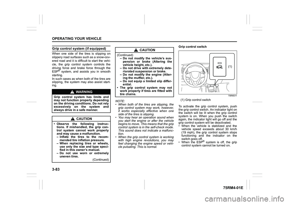
cle pulsating. This is normal. Grip control switch
75RM311
(1) Grip control switch
To activate the grip control system, push
the grip control switch. An indicator light on
the switch will be lit when the grip control
system is on. When you push the switch
again, the indicator light will go off and the
grip control system will be deactivated.
• When the vehicle is stabilized and the vehicle speed exceeds about 30 km/h
(19 mph), the grip control system stops
functioning and the indicator on the
switch goes off.
• When the ESP
® system is off, the grip
control system cannot be turned on.
WA R N I N G
Grip control system has limits and
may not function properly depending
on the driving conditions. Do not rely
excessively on the system and
always drive in a safe manner.
CAUTION
• Observe the following instruc- tions. If mishandled, the grip con-
trol system cannot work properly
and may cause a malfunction.
– Inflate the tires to the recom-mended tire inflation pressure.
– When replacing tires or wheels, use only the size and type speci-
fied in this owner’s manual.
– Do not use worn or extremely uneven tires. (Continued)
CAUTION
(Continued)– Do not modify the vehicle’s sus-
pension or brake (Altering the
vehicle heig ht, etc.).
– Do not drive with extremely dete-
riorated suspension or brake.
– Do not modify the engine (Alter- ing the muffler, etc.).
– Do not equip a limited slip differ- ential.
• The grip control system may not
work properly if tires are fitted with
tire chains.
(1)
Page 248 of 505
4-1DRIVING TIPS
75RM4-01E
52D078S
Running-in
Catalytic converter
80G106
The purpose of the catalytic converter is to
minimize the amount of harmful pollutants
in your vehicle’s exhaust. Use of leaded
fuel in vehicles equipped with catalytic
converters is prohibited, because lead
deactivates the pollutant-reducing compo-
nents of the catalyst system.
The converter is designed to last the life of
the vehicle under normal usage and when
unleaded fuel is used. No special mainte-
nance is required on the converter. How-
ever, it is very important to keep the engine
properly tuned. Engine misfiring, which can
result from an improperly tuned engine,
may cause overheating of the catalytic
converter. This may result in permanent
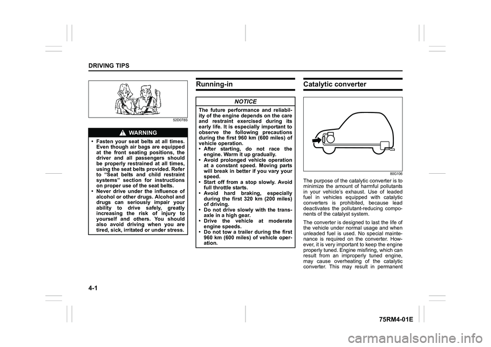
WA R N I N G
• Fasten your seat belts at all times.Even though air bags are equipped
at the front seating positions, the
driver and all passengers should
be properly restrained at all times,
using the seat belts provided. Refer
to “Seat belts and child restraint
systems” section for instructions
on proper use of the seat belts.
• Never drive under the influence of
alcohol or other drugs. Alcohol and
drugs can seriously impair your
ability to drive safely, greatly
increasing the risk of injury to
yourself and others. You should
also avoid driving when you are
tired, sick, irritated or under stress.
NOTICE
The future performance and reliabil-
ity of the engine depends on the care
and restraint exercised during its
early life. It is especially important to
observe the following precautions
during the first 960 km (600 miles) of
vehicle operation.
•After starting, do not race theengine. Warm it up gradually.
• Avoid prolonged vehicle operation at a constant speed. Moving parts
will break in better if you vary your
speed.
• Start off from a stop slowly. Avoid full throttle starts.
• Avoid hard braking, especially during the first 320 km (200 miles)
of driving.
• Do not drive slowly with the trans- axle in a high gear.
• Drive the vehicle at moderate
engine speeds.
• Do not tow a trailer during the first 960 km (600 miles) of vehicle oper-
ation.
Page 275 of 505
5-20
OTHER CONTROLS AND EQUIPMENT
75RM4-01E
75RM357
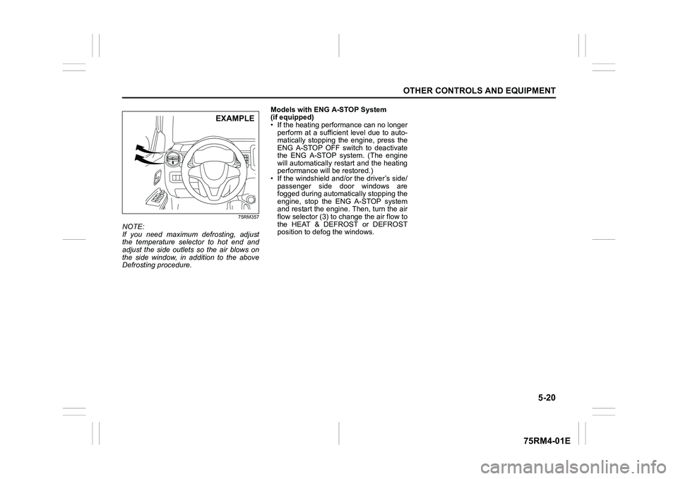
NOTE:
If you need maximum defrosting, adjust
the temperature selector to hot end and
adjust the side outlets so the air blows on
the side window, in addition to the above
Defrosting procedure.Models with ENG A-STOP System
(if equipped)
• If the heating performance can no longer
perform at a sufficient level due to auto-
matically stopping the engine, press the
ENG A-STOP OFF switch to deactivate
the ENG A-STOP system. (The engine
will automatically restart and the heating
performance will be restored.)
• If the windshield and/or the driver’s side/ passenger side door windows are
fogged during automatic ally stopping the
engine, stop the ENG A-STOP system
and restart the engine. Then, turn the air
flow selector (3) to c hange the air flow to
the HEAT & DEFROST or DEFROST
position to defog the windows.
EXAMPLE
Page 280 of 505
5-25OTHER CONTROLS AND EQUIPMENT
75RM4-01E
Models with ENG A-STOP System
(if equipped)
• If the heating performance can no longerperform at a sufficient level due to auto-
matically stopping the engine, press the
ENG A-STOP OFF switch to deactivate
the ENG A-STOP system. (The engine
will automatically restart and the air con-
ditioning performanc e will be restored.)
• If the windshield and/or the driver’s side/ passenger side door windows are
fogged during automatic ally stopping the
engine, stop the ENG A-STOP system
and restart the engine. Then, turn the air
flow selector (3) to change the air flow to
the HEAT & DEFROST or DEFROST
position to defog the windows.
MaintenanceIf you do not use the air conditioner for a
long period, such as during winter, it may
not give the best performance when you
start using it again. To help maintain opti-
mum performance and durability of your air
conditioner, it needs to be run periodically.
Operate the air conditioner at least once a
month for one minute with the engine
idling. This circulates the refrigerant and oil
and helps protect the internal components.
If your air conditioner is equipped with air
filters, clean or replace them as specified
in “Maintenance schedule” in the
“INSPECTION AND MAINTENANCE” sec-
tion.
(For vehicles using “HFO-1234yf” refrig-
erant)
NOTE:
Your vehicle uses the air conditioning
refrigerant HFO-1234yf, commonly called
R-1234yf. R-1234yf replaced R-134a for
automotive applications. Other refriger-
ants are available, but only R-1234yf
should be used in your vehicle.
NOTICE
Using the wrong refrigerant may
damage your air conditioning sys-
tem. Use R-1234yf only. Do not mix or
replace the R-1234yf with other refrig-
erants.
(Except for vehicles using “HFO-1234yf”
refrigerant)
NOTE:
Your vehicle uses the air conditioning
refrigerant HFC-134a, commonly called
R-134a. R-134a replaced R-12 around
1993 for automotive applications. Other
refrigerants are available, including recy-
cled R-12, but only R-134a should be used
in your vehicle.
NOTICE
Using the wrong refrigerant may
damage your air conditioning sys-
tem. Use R-134a only. Do not mix or
replace the R-134a with other refrig-
erants.
Page 286 of 505
5-31OTHER CONTROLS AND EQUIPMENT
75RM4-01E
Models with ENG A-STOP System
(if equipped)
• If the heating performance can no longerperform at a sufficient level due to auto-
matically stopping the engine, press the
ENG A-STOP OFF switch to deactivate
the ENG A-STOP system. (The engine
will automatically restart and the air con-
ditioning performanc e will be restored.)
• If the windshield and/or the driver’s side/ passenger side door windows are
fogged during automatic ally stopping the
engine, stop the ENG A-STOP system
and restart the engine. Then, turn the air
flow selector (4) to change the air flow to
the HEAT & DEFROST or DEFROST
position to defog the windows.
MaintenanceIf you do not use the air conditioner for a
long period, such as during winter, it may
not give the best performance when you
start using it again. To help maintain opti-
mum performance and durability of your air
conditioner, it needs to be run periodically.
Operate the air conditioner at least once a
month for one minute with the engine
idling. This circulates the refrigerant and oil
and helps protect the internal components.
If your air conditioner is equipped with air
filters, clean or replace them as specified
in “Maintenance schedule” in the
“INSPECTION AND MAINTENANCE” sec-
tion. Have this job done by your SUZUKI
dealer as the lower glove box must be low-
ered for this job.
(For vehicles using “HFO-1234yf” refrig-
erant)
NOTE:
Your vehicle uses the air conditioning
refrigerant HFO-1234yf, commonly called
R-1234yf. R-1234yf replaced R-134a for
automotive applications. Other refriger-
ants are available, but only R-1234yf
should be used in your vehicle. (Except for vehicles using “HFO-1234yf”
refrigerant)
NOTE:
Your vehicle uses the air conditioning
refrigerant HFC-134a, commonly called
R-134a. R-134a replaced R-12 around
1993 for automotive applications. Other
refrigerants are available, including recy-
cled R-12, but only R-134a should be used
in your vehicle.
NOTICE
Using the wrong refrigerant may
damage your air conditioning sys-
tem. Use R-1234yf only. Do not mix or
replace the R-1234yf with other refrig-
erants.
NOTICE
Using the wrong refrigerant may
damage your air conditioning sys-
tem. Use R-134a only. Do not mix or
replace the R-134a with other refrig-
erants.
Page 393 of 505
7-44
INSPECTION AND MAINTENANCE
75RM4-01E
To remove the battery:
1) Disconnect the negative cable (1).
2) Disconnect the positive cable (2).
For vehicles without ENG A-STOP sys-
tem;
3) Remove the retainer nuts (3) and remove the retainer (4).
For vehicles with ENG A-STOP system ;
3) Remove the bracket bolt (3) and remove the bracket (4).
4) Remove the battery.
To install the battery:
1) Install the battery in the reverse order of removal.
2) Tighten the bracket bolt and battery cables securely.
NOTE:
When the battery is disconnected, some of
the vehicle’s function will be initialized and/
or deactivated.
These function are required to reset after
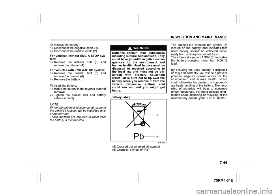
the battery is reconnected. (Battery label)
51KM042
(5) Crossed-out
wheeled bin symbol
(6) Chemical symbol of “Pb” The crossed-out wheeled bin symbol (5)
located on the battery label indicates that
used battery should be collected sepa-
rately from ordinary household trash.
The chemical symbol of “Pb” (6) indicates
the battery contains more than 0.004%
lead.
By ensuring the used battery is disposed
or recycled correctly, you will help prevent
potential negative consequences for the
environment and human health, which
could otherwise be caused by inappropri-
ate trash handling of the battery. The recy-
cling of materials will help to conserve
natural resources. For more detailed infor-
mation about disposing or recycling of the
used battery, consult your SUZUKI dealer.
WA R N I N G
Batteries contain toxic substances
including sulfuric acid and lead. They
could have potential negative conse-
quences for the environment and
human health. Used
battery must be
disposed or recycled according to
the local law and must not be dis-
carded with ordinary household
waste. Make sure not to tip over the
battery when you remove it from the
vehicle. Otherwise, sulfuric acid
could run out and you might get
injury.
Pb
(5)(6)