warning light SUZUKI IGNIS 2022 Owners Manual
[x] Cancel search | Manufacturer: SUZUKI, Model Year: 2022, Model line: IGNIS, Model: SUZUKI IGNIS 2022Pages: 505, PDF Size: 8.36 MB
Page 4 of 505
75RM4-01E
IMPORTANT
WARNING/CAUTION /NOTICE /
NOTE
Please read this manual and follow its
instructions carefully. To emphasize spe-
cial information, the symbol and the
words WARNING , CAUTION , NOTICE
and NOTE have special meanings. Pay
particular attention to messages high-
lighted by these signal words:
NOTE:
Indicates special information to make
maintenance easier or instructions clearer.
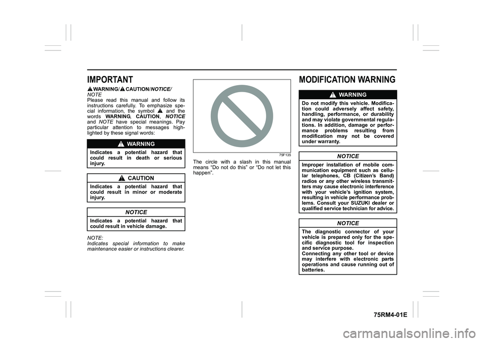
75F135
The circle with a slash in this manual
means “Do not do this” or “Do not let this
happen”.
MODIFICATION WARNING
WA R N I N G
Indicates a potential hazard that
could result in death or serious
injury.
CAUTION
Indicates a potential hazard that
could result in minor or moderate
injury.
NOTICE
Indicates a potential hazard that
could result in vehicle damage.
WA R N I N G
Do not modify this vehicle. Modifica-
tion could adversely affect safety,
handling, performance, or durability
and may violate governmental regula-
tions. In addition, damage or perfor-
mance problems resulting from
modification may not be covered
under warranty.
NOTICE
Improper installation of mobile com-
munication equipment such as cellu-
lar telephones, CB (Citizen’s Band)
radios or any other wireless transmit-
ters may cause electronic interference
with your vehicle’s ignition system,
resulting in vehicle performance prob-
lems. Consult your SUZUKI dealer or
qualified service technician for advice.
NOTICE
The diagnostic connector of your
vehicle is prepared only for the spe-
cific diagnostic tool for inspection
and service purpose.
Connecting any other tool or device
may interfere with electronic parts
operations and cause running out of
batteries.
Page 17 of 505
ILLUSTRATED TABLE OF CONTENTS
75RM4-01E
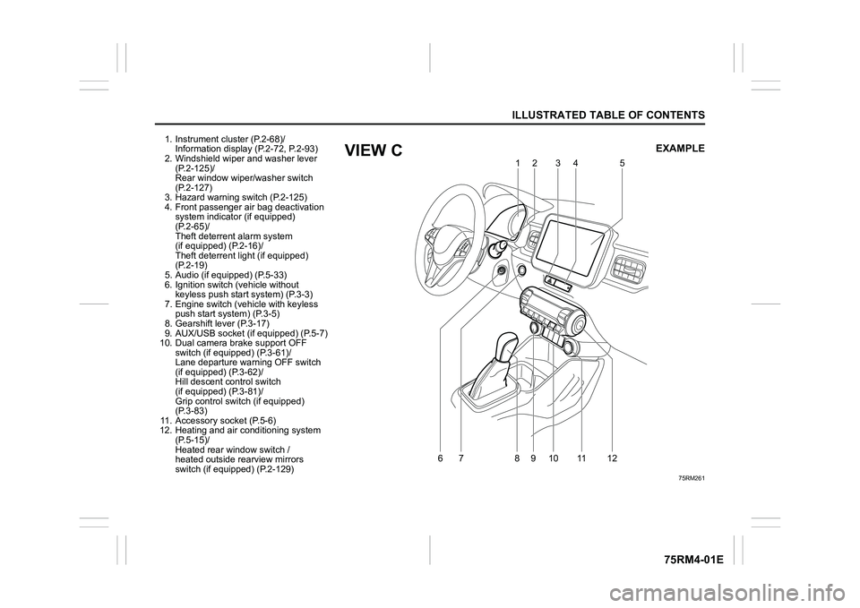
1. Instrument cluster (P.2-68)/Information display (P.2-72, P.2-93)
2. Windshield wiper and washer lever
(P.2-125)/
Rear window wiper/washer switch
(P.2-127)
3. Hazard warning switch (P.2-125)
4. Front passenger air bag deactivation system indicator (if equipped)
(P.2-65)/
Theft deterren t alarm system
(if equipped) (P.2-16)/
Theft deterrent light (if equipped)
(P.2-19)
5. Audio (if equipped) (P.5-33)
6. Ignition switch (vehicle without keyless push start system) (P.3-3)
7. Engine switch (v ehicle with keyless
push start system) (P.3-5)
8. Gearshift lever (P.3-17)
9. AUX/USB socket (if equipped) (P.5-7)
10. Dual camera brake support OFF switch (if equipped) (P.3-61)/
Lane departure warning OFF switch
(if equipped) (P.3-62)/
Hill descent control switch
(if equipped) (P.3-81)/
Grip control switch (if equipped)
(P.3-83)
11. Accessory socket (P.5-6)
12. Heating and air co nditioning system
(P.5-15)/
Heated rear window switch /
heated outside rearview mirrors
switch (if equipped) (P.2-129)
75RM261
6
79
10 11
812 12
5
34
EXAMPLE
VIEW C
Page 23 of 505
BEFORE DRIVING
2
75RM4-01E
60G404
Keys ......................................................................................2-1
Door locks .................................................... ........................2-2
Keyless push start system remote controller /
Keyless entry system transmitte r (if equipped) ................2-7
Theft deterrent alarm system (if equipped) .................... ...2-16
Theft deterrent light (if equipped) ........................... ...........2-19
Windows ....................................................... ........................2-20
Mirrors ....................................................... ...........................2-23
Front seats ................................................... ........................2-27
Rear seats .................................................... .........................2-29
BEFORE DRIVINGSeat belts and child restraint systems ........................ ...... 2-33
Child restraint system f or countries applied for
UN Regulation No.16 ........................................... ................ 2-43
Supplemental restraint system (air bags) ...................... ... 2-54
Instrument cluster ............................................ ................... 2-68
Speedometer ................................................... .................... 2-69
Tachometer (if equipped) ...................................... ............. 2-69
Fuel gauge .................................................... ....................... 2-70
Brightness control ............................................ .................. 2-70
Information display
(instrument clus ter with tachometer) .......................... ...... 2-72
Information display
(instrument clus ter without tachometer) ....................... ... 2-93
Warning and indicator lights .................................. .......... 2-101
Lighting control lever ........................................ ............... 2-116
Headlight leveling switch (if equipped) ....................... .... 2-123
Turn signal control lever ..................................... ............. 2-123
Hazard warning switch ......................................... ............ 2-125
Windshield wiper and washer lever ............................. ... 2-125
Tilt steering lock lever ... ................................................... 2-128
Horn .......................................................... .......................... 2-128
Heated rear window switch /
heated outside rearview mirror switch (if equipped) ..... 2-129
Page 24 of 505
2-1BEFORE DRIVING
75RM4-01E
Keys
54G489
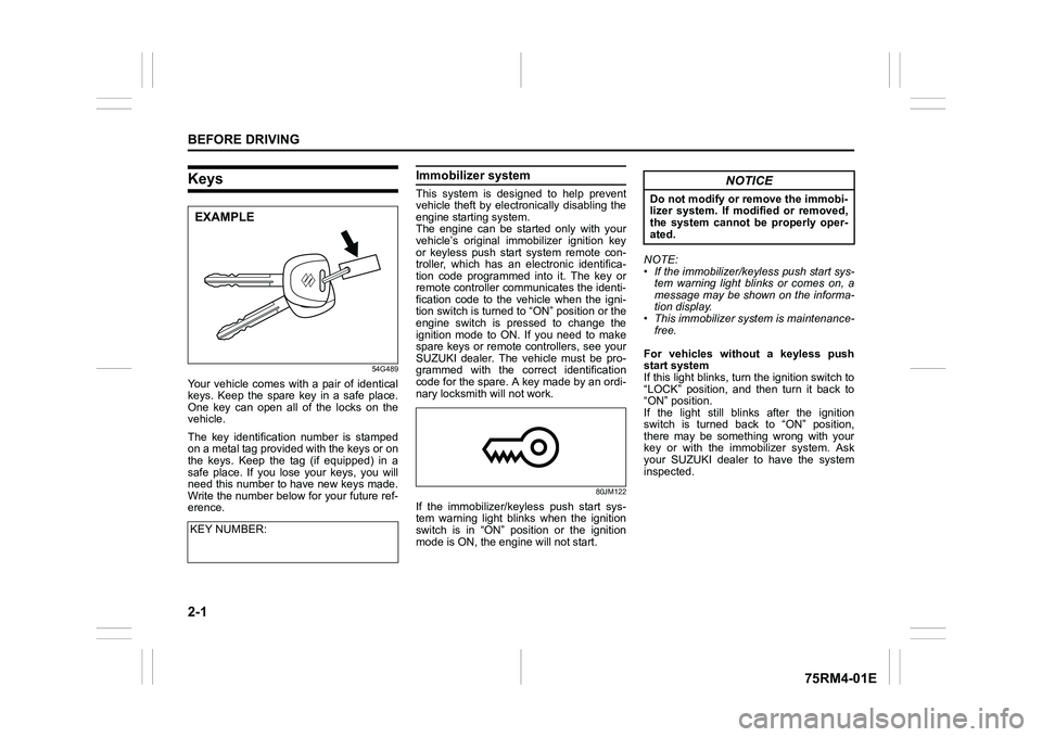
Your vehicle comes with a pair of identical
keys. Keep the spare key in a safe place.
One key can open all of the locks on the
vehicle.
The key identification number is stamped
on a metal tag provided with the keys or on
the keys. Keep the tag (if equipped) in a
safe place. If you lose your keys, you will
need this number to have new keys made.
Write the number below for your future ref-
erence.
Immobilizer system This system is designed to help prevent
vehicle theft by electronically disabling the
engine starting system.
The engine can be started only with your
vehicle’s original immobilizer ignition key
or keyless push start system remote con-
troller, which has an electronic identifica-
tion code programmed into it. The key or
remote controller communicates the identi-
fication code to the vehicle when the igni-
tion switch is turned to “ON” position or the
engine switch is pressed to change the
ignition mode to ON. If you need to make
spare keys or remote controllers, see your
SUZUKI dealer. The vehicle must be pro-
grammed with the correct identification
code for the spare. A key made by an ordi-
nary locksmith will not work.
80JM122
If the immobilizer/keyless push start sys-
tem warning light blinks when the ignition
switch is in “ON” position or the ignition
mode is ON, the engine will not start. NOTE:
• If the immobilizer/keyless push start sys-
tem warning light blinks or comes on, a
message may be shown on the informa-
tion display.
• This immobilizer system is maintenance-
free.
For vehicles without a keyless push
start system
If this light blinks, tur n the ignition switch to
“LOCK” position, and then turn it back to
“ON” position.
If the light still blinks after the ignition
switch is turned back to “ON” position,
there may be something wrong with your
key or with the immobilizer system. Ask
your SUZUKI dealer to have the system
inspected.
KEY NUMBER:
EXAMPLE
NOTICE
Do not modify or remove the immobi-
lizer system. If modified or removed,
the system cannot be properly oper-
ated.
Page 25 of 505
2-2
BEFORE DRIVING
75RM4-01E
For vehicles with a keyless push start
system
If this light blinks, change the ignition mode
to LOCK (OFF), and then change it back to
ON. Also refer to “If the master warning
indicator light blinks and the engine cannot
be started” in “Starting engine (vehicle with
keyless push start system)” in the “OPER-
ATING YOUR VEHICLE” section.
If the light still blinks after the ignition mode
is changed back to ON, there may be
something wrong with your key or with the
immobilizer system. Ask your SUZUKI
dealer to have the system inspected.
The immobilizer/keyless push start system
warning light may also blinks if the remote
controller is not in the vehicle when you
close the door or attempt to start the
engine.
NOTE:
• If you lose your immobilizer ignition key or remote controller, ask your SUZUKI
dealer as soon as possible to deactivate
the lost one, and to make a new key or
remote controller.
• If you own other v ehicles with immobi-
lizer keys, keep those keys away from
the ignition switch or the engine switch
when using your SUZUKI vehicle. Other-
wise, or the engine may not be started
because they may interfere with your
SUZUKI vehicle’s immobilizer system. • If you attach any metal objects to the
immobilizer key or remote controller, it
may not start the engine.
Ignition key reminderA buzzer sounds intermittently to remind
you to remove the ignition key if it is in the
ignition switch when the driver’s door is
opened.
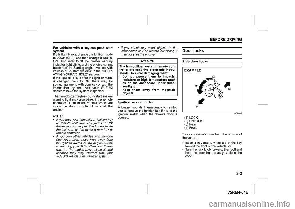
Door locksSide door locks
60B008
(1) LOCK
(2) UNLOCK
(3) Rear
(4) Front
To lock a driver’s door from the outside of
the vehicle:
• Insert a key and turn the top of the key toward the front o f the vehicle, or
• Turn the lock knob forward, then pull and
hold the door handle as you close the
door.
NOTICE
The immobilizer key and remote con-
troller are sensitive electronic instru-
ments. To avoid damaging them:
• Do not expose them to impacts,moisture or high temperature such
as on the dashboard under direct
sunlight.
• Keep them away from magnetic
objects.
(2)
(1) (3)
(4)
EXAMPLE
Page 34 of 505
2-11BEFORE DRIVING
75RM4-01E
57L21016
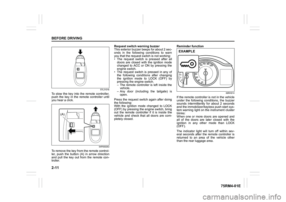
To stow the key into the remote controller,
push the key in the remote controller until
you hear a click.
54P000263
To remove the key from the remote control-
ler, push the button (A) in arrow direction
and pull the key out from the remote con-
troller.Request switch warning buzzer
This exterior buzzer beeps for about 2 sec-
onds in the following conditions to warn
you that the request s
witch is not working:
• The request switch is pressed after all doors are closed with the ignition mode
changed to ACC or ON by pressing the
engine switch.
• The request switch is pressed in any of
the following conditions after changing
the ignition mode to LOCK (OFF) by
pressing the engine switch.
– The remote controller is left inside thevehicle.
– Any door (including the tailgate) is
open.
Press the request switch again after doing
the following:
With the ignition mode changed to LOCK
(OFF) by pressing the engine switch, bring
out the remote controller if it is inside the
vehicle and check that all doors are com-
pletely closed. Reminder function
66RH014
If the remote controller is not in the vehicle
under the following conditions, the buzzer
sounds intermittently for about 2 seconds
and the immobilizer/keyless push start sys-
tem warning light on the instrument cluster
blinks:
When one or more doors are opened and
all of the doors are later closed with the
ignition in any other mode than LOCK
(OFF).
The indicator light will turn off within sev-
eral seconds after the remote controller is
returned to an area of the vehicle other
than the rear luggage area.
(A)
EXAMPLE
Page 41 of 505
2-18
BEFORE DRIVING
75RM4-01E
Checking whether the alarm has been
triggered during parking
If the alarm was triggered due to an unau-
thorized entry into the vehicle and you then
press the engine switch to change the igni-
tion mode to ON or turn the ignition switch
to “ON” position, the theft deterrent light
will blink rapidly for about 8 seconds and a
buzzer will beep 4 times during this period.
If this happens, check whether your vehi-
cle has been broken into while you were
away from it.
Enabling and disabling the theft deter-
rent alarm system
The theft deterrent alarm system can be
either enabled or disabled.
When enabled (factory setting)
When the system is enabled, it causes the
hazard warning lights to flash for about 40
seconds if any of the alarm trigger condi-
tions is met. The system also causes the
interior buzzer to beep intermittently for
about 10 seconds, which is followed by
intermittent sounding of the horn for about
30 seconds.
The theft deterrent light continues to blink
during this time.
When disabled
When the system is disabled, it stays dis-
armed even if you perform any system
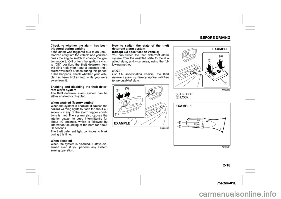
arming operation. How to switch the state of the theft
deterrent alarm system
(Except EU specification vehicle)
You can switch the theft deterrent alarm
system from the enabled
state to the dis-
abled state, and vice versa, using the fol-
lowing method.
NOTE:
For EU specification vehicle, the theft
deterrent alarm system cannot be switched
to the disabled state.
75RM157 75RM158
(2) UNLOCK
(3) LOCK
75RM204
(2)
(1) (3)EXAMPLE
(2)
(3)
(4)
EXAMPLE
(6)
(5)EXAMPLE
Page 48 of 505
2-25BEFORE DRIVING
75RM4-01E
Remote folding mirrors (if equipped)When the outside rearview mirrors folding
switch is in the unfolded position, the out-
side rearview mirrors are folded or
unfolded in conjunction with the door lock-
ing or engine switch operation.
• When you lock the doors (including the tailgate) by using the remote controller
or pushing the request switch, the mir-
rors will be folded automatically.
• To unfold the mirrors, push the engine switch to change the ignition mode to
ACC or ON.
• The factory setting is that the function is enabled. You can switch the function
from enabled to disabled, and vice
versa. To switch the function for your
preference, refer to “How to switch the
remote folding mi rrors function”. NOTE:
• If the doors are locked by using the key,
lock knob on a door or power door lock-
ing switch, the mirrors will not be folded
automatically.
• If the outside rearview mirrors folding
switch is in the folded position, the mir-
rors will not be unfolded automatically,
even when the engine switch is pushed
to change the ignition mode to ACC or
ON.
• If any of the doors is not opened within
about 30 seconds after the doors are
unlocked by using the keyless push start
system remote controller or request
switch, the doors will be locked again
and the mirrors will be folded automati-
cally. How to switch the remote folding mir-
rors function
When the ignition mode is LOCK (OFF),
you can switch the function from the
enabled state to the disabled state, and
vice versa, using the following method.
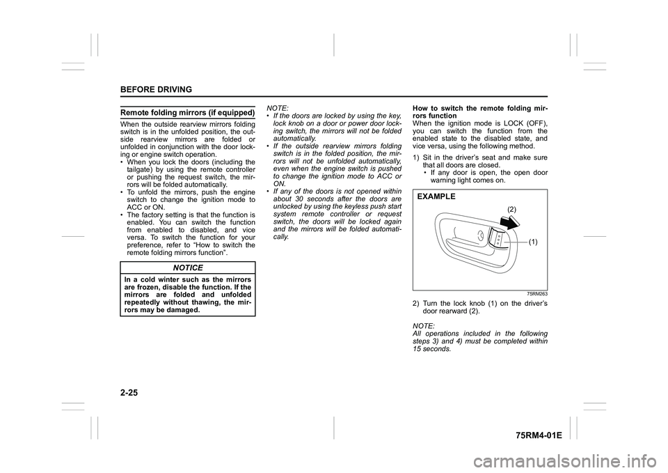
1) Sit in the driver’s seat and make sure
that all doors are closed.
• If any door is open, the open door warning light comes on.
75RM263
2) Turn the lock knob (1) on the driver’s door rearward (2).
NOTE:
All operations included in the following
steps 3) and 4) must be completed within
15 seconds.
NOTICE
In a cold winter such as the mirrors
are frozen, disable the function. If the
mirrors are folded and unfolded
repeatedly without thawing, the mir-
rors may be damaged.
(1)
(2)
EXAMPLE
Page 91 of 505
2-68
BEFORE DRIVING
75RM4-01E
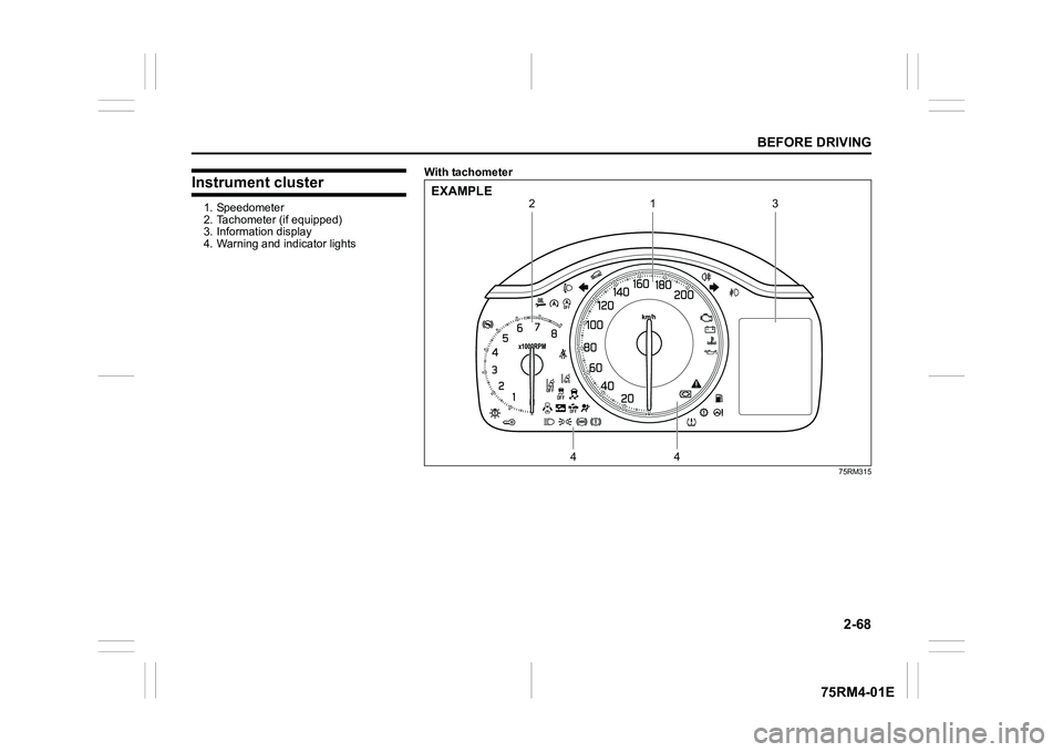
Instrument cluster1. Speedometer
2. Tachometer (if equipped)
3. Information display
4. Warning and indicator lightsWith tachometer
75RM315
1
4
4
2
3
EXAMPLE
Page 93 of 505
2-70
BEFORE DRIVING
75RM4-01E
Fuel gaugeWith tachometer
75RM248
Without tachometer
75RM249
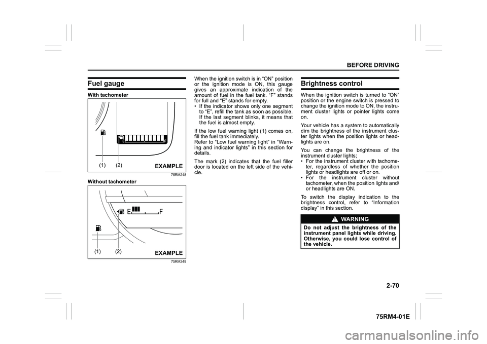
When the ignition switch is in “ON” position
or the ignition mode is ON, this gauge
gives an approximate indication of the
amount of fuel in the fuel tank. “F” stands
for full and “E” stands for empty.
• If the indicator shows only one segmentto “E”, refill the tank as soon as possible.
If the last segment blinks, it means that
the fuel is almost empty.
If the low fuel warning light (1) comes on,
fill the fuel tank immediately.
Refer to “Low fuel warning light” in “Warn-
ing and indicator lights” in this section for
details.
The mark (2) indicates that the fuel filler
door is located on the left side of the vehi-
cle.
Brightness controlWhen the ignition switch is turned to “ON”
position or the engine switch is pressed to
change the ignition mode to ON, the instru-
ment cluster lights or pointer lights come
on.
Your vehicle has a system to automatically
dim the brightness of the instrument clus-
ter lights when the position lights or head-
lights are on.
You can change the brightness of the
instrument cluster lights;
• For the instrument c luster with tachome-
ter, regardless of whether the position
lights or headlights are off or on.
• For the instrum ent cluster without
tachometer, when the position lights and/
or headlights are ON.
To switch the display indication to the
brightness control, re fer to “Information
display” in this section.
(1)
(2)
EXAMPLE
(1)
(2)
EXAMPLE
WA R N I N G
Do not adjust the brightness of the
instrument panel lights while driving.
Otherwise, you could lose control of
the vehicle.