Engine power SUZUKI IGNIS 2022 User Guide
[x] Cancel search | Manufacturer: SUZUKI, Model Year: 2022, Model line: IGNIS, Model: SUZUKI IGNIS 2022Pages: 505, PDF Size: 8.36 MB
Page 208 of 505
3-55OPERATING YOUR VEHICLE
75RM4-01E
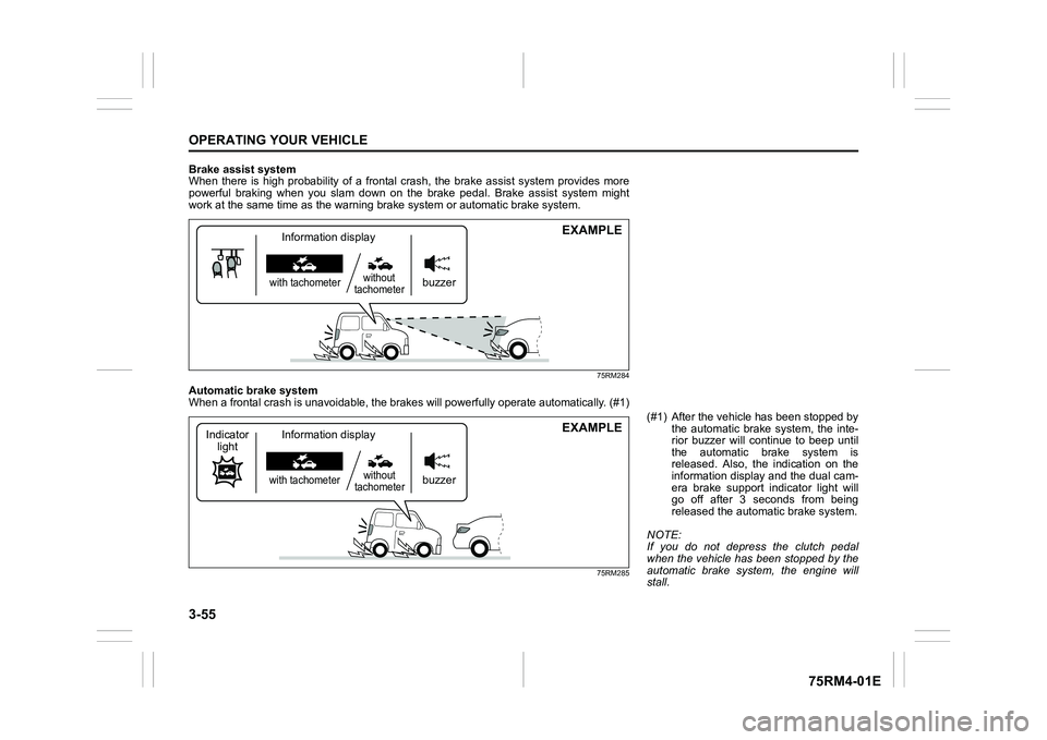
Brake assist system
When there is high probability of a frontal crash, the brake assist system provides more
powerful braking when you slam down on the brake pedal. Brake a ssist system might
work at the same tim e as the warning brak e system or automatic brake system.
75RM284
Automatic brake system
When a frontal crash is unavoidable, the brakes will powerfully operate automatically. (#1)
75RM285
EXAMPLE
buzzer
with tachometerwithout
tachometerInformation display
EXAMPLE
buzzer
with tachometer without
tachometer
Information display
Indicator
light
(#1) After the vehicl e has been stopped by
the automatic brake system, the inte-
rior buzzer will continue to beep until
the automatic brake system is
released. Also, the indication on the
information display and the dual cam-
era brake support indicator light will
go off after 3 seconds from being
released the automatic brake system.
NOTE:
If you do not depress the clutch pedal
when the vehicle has been stopped by the
automatic brake system, the engine will
stall.
Page 212 of 505
3-59OPERATING YOUR VEHICLE
75RM4-01E
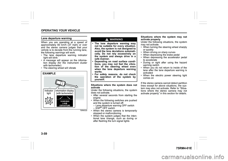
Lane departure warningWhen you are operating at a speed of
approximately 60 km/h (37 mph) or over
and the stereo camera judges that your
vehicle is to deviate from the running lane,
the following warnings will work.
• The lane departure warning indicatorlight will blink
• A message will appear on the informa-
tion display (for the instrument cluster
with tachometer)
• The steering wheel will vibrate
75RM330
Situations where the system does not
activate
Under the following situations, the system
does not activate.
• After several seconds from starting the engine
• When the following switches are pushed and the system is turned off:
– Lane departure warning OFF switch
– ESP
® OFF switch
• When the stereo camera is temporarily stopped or malfunctioning
• When the system judges that the inten- tional lane change, such as during or
after flashing the turn signal lights Situations where the system may not
activate properly
Under the following situations, the system
may not activate.
• When turning the steering wheel sharply
or quickly
• When driving on sharp curves
• When depressing the brake pedal
• When depressing the accelerator pedal to accelerate
• During or right after using the hazard warning switch
• When you do not return to inside of the lane after the lane departure warning is
activated
• When the electric power steering light comes on
If the stereo camera cannot detect partition
lines except for above situations, the sys-
tem may also not activ ate. Refer to “Situa-
tions where the stereo camera may not
activate properly” in this section for details.
EXAMPLEIndicator light Information display
(with tachometer)
WA R N I N G
• The lane departure warning may not be suitable for every situation.
Also, the system is not designed to
avoid the lane deviations automati-
cally. Do not rely excessively on
the system and always drive in a
safe manner.
• Depending on road surface condi-
tions, you may not feel the vibra-
tion of the steering wheel even
when the lane departure warning
works.
• For safety reasons, do not check
the operation of the system by
yourself.
Page 219 of 505
3-66
OPERATING YOUR VEHICLE
75RM4-01E
Temporary stop of the stereo camera
Under the following situations, the function
of the stereo camera stops temporarily.
When the situations are improved, the
temporary stop of the function will be can-
celed.
• When the visibility of the stereo camerais poor
• When the temperature of the body of
stereo camera i s low or high
• When the systems related the dual cam- era brake support stops temporarily
• When the lead-acid battery has a volt- age abnormality
• When the automatic adjustment of the
stereo camera is insufficient
Failure of the stereo camera
When the stereo camera is failure, the
function of the stereo camera stops until
the ignition switch is turned to “LOCK”
position or the engine switch is pressed to
change the ignition mode to LOCK (OFF).
Find a safe place to park and turn the igni-
tion switch to “LOCK” position or change
the ignition mode to LOCK (OFF) by press-
ing the engine switch.
Restart the engine, and check that the dual
camera brake support indicator light and
lane departure warning indicator light go
off.
• If both of the indicators stay on after restarting the engine, there may be a
failure of the stereo camera. Ask your
SUZUKI dealer to have the stereo cam-
era inspected. It is thought that the cause of failure is the
followings.
• When the stereo camera has an abnor-
mality
• When the temperature of the body of stereo camera is t oo low or too high
• When the mounting position of the ste- reo camera is shifted greatly
• When there are communication abnor-
malities among the engine, transaxle
and brake controller
• When the dual camera brake support
OFF switch has an abnormality
• When the steering angle sensor has an abnormality
• When the power supply of the stereo camera is cut
NOTE:
• Under the following situations, the dual camera brake support indicator light and
lane departure warning indicator light
come on after the engine has started, it
does not indicate a malfunction. Once
the ignition switch is turned to “LOCK”
position or the engine switch is pressed
to change the ignition mode to LOCK
(OFF) and then the engine is restarted,
these indicators will go off.
– When the automatic brake system hasbeen operating 3 times
– When the automatic brake system has
been operating for long periods • The function of the stereo camera stops
if the dual camera brake support indica-
tor light and lane departure warning indi-
cator light come on and there may be a
failure of the stereo camera, but it does
not hinder normal driving.
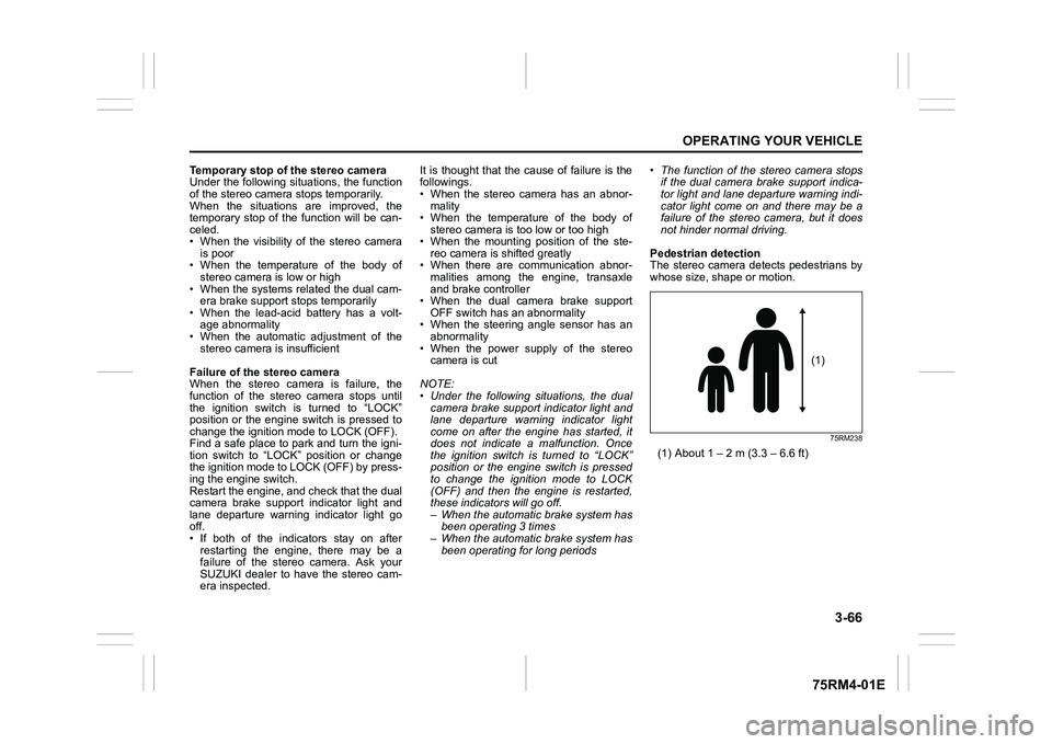
Pedestrian detection
The stereo camera detects pedestrians by
whose size, shape or motion.
75RM238
(1) About 1 – 2 m (3.3 – 6.6 ft)
(1)
Page 228 of 505
3-75OPERATING YOUR VEHICLE
75RM4-01E
If the rear view from the rearview cam-
era is not shown or there is a poor
image
• If the rear view from the rearview camerais not shown.
– Check that the ignition switch is in
“ON” position or the ignition mode is
ON.
– Check that the gearshift lever is
shifted to “R” position.
• If the image from the rearview camera is poor.
– Check that the camera lens is not dirty.
– Check that light from the sun or thebeam of the headlights from the vehi-
cle behind is not shining directly into
the lens.
If the rearview camera system is still not
working properly after checking the above,
have the system inspected by an autho-
rized SUZUKI dealer as soon as possible.
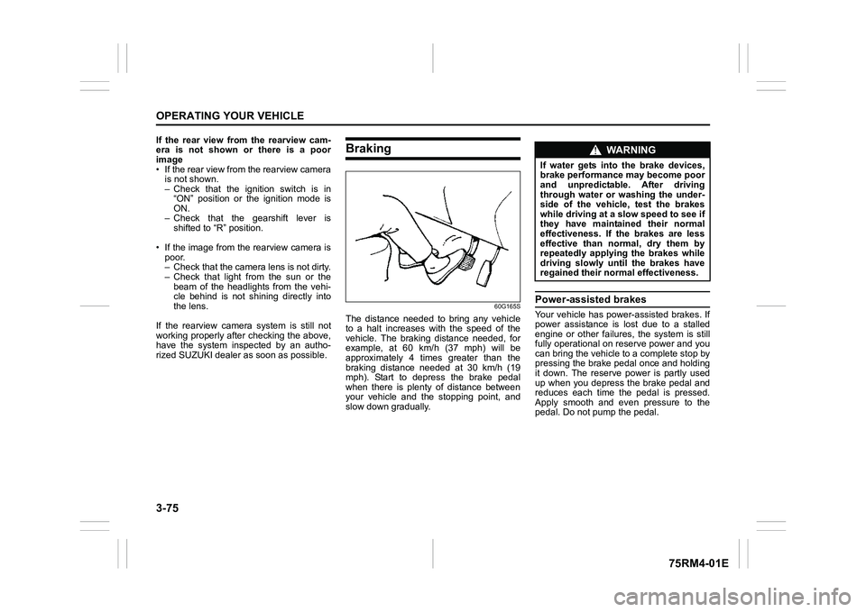
Braking
60G165S
The distance needed to bring any vehicle
to a halt increases with the speed of the
vehicle. The braking distance needed, for
example, at 60 km/h (37 mph) will be
approximately 4 times greater than the
braking distance needed at 30 km/h (19
mph). Start to depress the brake pedal
when there is plenty of distance between
your vehicle and the stopping point, and
slow down gradually.
Power-assisted brakesYour vehicle has power-assisted brakes. If
power assistance is lo st due to a stalled
engine or other failure s, the system is still
fully operational on reserve power and you
can bring the vehicle to a complete stop by
pressing the brake pedal once and holding
it down. The reserve power is partly used
up when you depress the brake pedal and
reduces each time the pedal is pressed.
Apply smooth and even pressure to the
pedal. Do not pump the pedal.
WA R N I N G
If water gets into the brake devices,
brake performance may become poor
and unpredictable. After driving
through water or washing the under-
side of the vehicle, test the brakes
while driving at a slow speed to see if
they have maintained their normal
effectiveness. If the brakes are less
effective than normal, dry them by
repeatedly applying the brakes while
driving slowly until the brakes have
regained their normal effectiveness.
Page 229 of 505
3-76
OPERATING YOUR VEHICLE
75RM4-01E
Brake assist systemWhen you slam the brakes on, the brake
assist system determines it to be an emer-
gency stop and provides more powerful
braking for a driver who cannot hold down
the brake pedal firmly.
NOTE:
If you quickly and forcefully depress the
brakes, you may hear clicking sound by
the brake assist system operation. This is
normal and indicates that the brake assist
system is activated properly.
Anti-lock brake system (ABS)ABS will help you avoid skidding by elec-
tronically controlling braking pressure. It
will also help you maintain steering control
when braking on slippery surfaces or when
braking hard.
The ABS works automatically, so you do
not need any special braking technique.
Just push the brake pedal down without
pumping. The ABS will operate whenever
it senses that the wheels are locking up.
You may feel the brake pedal move a little
while the ABS is operating.
NOTE:
• The ABS will not work if vehicle speed is under about 9 km/h (6 mph).
• If the ABS system is activated, you may
hear a clunking noise and/or feel pulsat-
ing in the brake pedal. This is normal
and indicates that the brake fluid pres-
sure is being controlled properly.
• You may hear an operation sound when you start the engine or after the vehicle
begins to move. This means that the
above systems are in the self-check
mode. This sound does not indicate a
malfunction.
WA R N I N G
Even without reserve power in the
brake system, you can still stop the
vehicle by pressing the brake pedal
harder than normally required. How-
ever, the stopping distance may be
longer.
WA R N I N G
• On some types of loose surfaces (such as gravel, snow-covered
roads, etc.), the stopping distance
required for a vehicle with ABS
may be slightly greater than the
one required for a comparable vehi-
cle with a conventional brake sys-
tem. With a conventional brake
system, skidding tires are able to
plow the gravel or snow layer,
shortening the stopping distance.
ABS minimizes this resistance
effect. Allow for extra stopping dis-
tance when driving on loose sur-
faces.
• On regular paved roads, some driv-
ers may be able to obtain slightly
shorter stopping distances with
conventional brake systems than
with ABS.
• In both of the above conditions, ABS will still offer the advantage of
helping you maintain directional
control. However, remember that
ABS will not compensate for bad
road or weather conditions or poor
driver judgment. Use good judg-
ment and do not drive too fast.
Page 231 of 505
3-78
OPERATING YOUR VEHICLE
75RM4-01E
Electronic stability program (ESP
®) (if equipped)
ESP
® is a registered trademark of Daimler
AG.
The Electronic Stability Program (ESP
®)
helps to control the vehicle during corner-
ing if front wheels or rear wheels skid. It
also assists you in maintaining traction
while accelerating on loose or slippery
road surfaces. It does this by regulating
the engine’s output, and by selectively
applying the brakes. In addition, ESP®
helps to avoid skidding by controlling brak-
ing pressure. The ESP
® has the following three sys-
tems:
Stability control systemThe vehicle stability control system helps
provide integrated control of systems such
as anti-lock brakes, traction control, engine
control, etc. This system automatically
controls the brakes and engine to help pre-
vent the vehicle from skidding when cor-
nering on a slippery road surface or when
turning the steering wheel abruptly.Traction control systemThe traction control system automatically
helps prevent the spinning of wheels when
the vehicle is started or accelerated on
slippery road surfaces. The system oper-
ates only if it senses that some of the
wheels are spinning or beginning to lose
traction. When this happens, the system
operates the front or rear brakes and
reduces engine power to limit wheel spin.
Anti-lock brake system (ABS)ABS will help you avoid skidding by elec-
tronically controlling braking pressure. It
will also help you maintain steering control
when braking on slippery surfaces or when
braking hard. The ABS works automati-
cally, so you do not have to use any spe-
cial braking technique. Just push the brake
pedal down wit hout pumping. The ABS will
operate whenever it senses that wheels
are locking up. You may feel the brake
pedal pulsate while the ABS is operating.
(For more information on ABS, see “Brak-
ing” in this section.)
NOTE:
The ABS will not work if vehicle speed is
under about 9 km/h (6 mph).
WA R N I N G
The ESP
® cannot enhance the vehi-
cle’s driving stability in all situations
and does not control your vehicle’s
entire braking system. The ESP
® can-
not prevent accidents, including
those resulting from excessive speed
in turns, or hydroplaning. Only safe
and attentive drive can prevent acci-
dents. The capabilities of an ESP
®-
equipped vehicle must never be used
as a substitute for careful driving.
WA R N I N G
• The ESP
® may not work properly if
tires or wheels other than those
specified in the owner’s manual are
used. When replacing tires or
wheels, use only the size and type
specified in this owner’s manual.
• The ESP® may not work properly if
tires are not inflated to the recom-
mended tire inflation pressure.
• The ESP® may not work properly if
tires are fitted wi th tire chains.
(Continued)
Page 237 of 505
3-84
OPERATING YOUR VEHICLE
75RM4-01E
How grip control system works
When the grip control switch is on and one
side of the tires is slipping, the grip control
system assists you in smooth starting by
controlling the driving force and brake
force of all wheels.
• When the ESP
® system is off, the grip
control system cannot be activated.
NOTE:
While the grip control system is working,
the ESP
® warning light blinks.
Hill hold control sys tem (if equipped)The hill hold control system is designed to
assist you in starting to move up hills.
When you start to move up a hill, the sys-
tem helps to prevent the vehicle from roll-
ing downward (for approximately 2
seconds) while you move your foot from
the brake pedal to the accelerator pedal.
The hill hold control system activates for a
maximum of about 2 seconds if your foot is
moved from the brake pedal when the fol-
lowing conditions are all met.
1) The gearshift lever is in a forward gear or reverse gear.
2) The parking brake is released.
3) For manual transaxle models, the clutch pedal is depressed.
4) The vehicle is o n an upward incline.
CAUTION
To activate the grip control system,
push the grip control switch and
check that the indicator on the switch
turns on.
WA R N I N G
• Do not rely excessively on the hill
hold control system. The hill hold
control system may not prevent the
vehicle from rolling downward on a
hill under all load or road condi-
tions. Always be prepared to
depress the brake pedal to prevent
the vehicle from rolling downward.
Failure to pay attention and
depress the brake pedal to hold the
vehicle on a hill when necessary,
may result in loss of control or an
accident.
• The hill hold control system is not designed to stop the vehicle on a
hill. (Continued)
WA R N I N G
(Continued)
• After you release your foot from the
brake pedal, accelerate the vehicle
to move up immediately. If you
release your foot from the brake
pedal over 2 seconds, the hill hold
control system will be canceled. If
so, the vehicle may roll downward,
which can result in an accident
depending on the degree of slope.
And, the engine may stall and the
power assist for the steering and
brakes will not work so steering
and braking will be much harder
than usual which can result in an
accident or vehicle damage.
Page 251 of 505
4-4
DRIVING TIPS
75RM4-01E
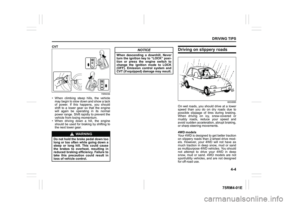
CVT
75RM296
• When climbing steep hills, the vehiclemay begin to slow down and show a lack
of power. If this happens, you should
shift to a lower gear so that the engine
will again be operating in its normal
power range. Shift rapidly to prevent the
vehicle from losing momentum.
• When driving down a hill, the engine
should be used for braking by shifting to
the next lower gear.
Driving on slippery roads
60G089S
On wet roads, you shou ld drive at a lower
speed than you do on dry roads due to
possible slippage of tires during braking.
When driving on icy, snow-covered or
muddy roads, reduce your speed and
avoid sudden acceleration, abrupt braking,
or sharp steering movements.
4WD models
Your 4WD is designed to get better traction
on slippery roads than 2-wheel drive mod-
els. However, your 4WD will not have as
much traction in deep snow, mud or sand
as multipurpose 4WD vehicles. You should
not attempt to drive your 4WD in deep
snow, mud or sand. 4WD models are not
sport/utility vehicles, and are not designed
for off-road use.
WA R N I N G
Do not hold the brake pedal down too
long or too often while going down a
steep or long hill. This could cause
the brakes to overheat, resulting in
reduced braking efficiency. Failure to
take this precaution could result in
loss of vehicle control.
NOTICE
When descending a downhill, Never
turn the ignition key to “LOCK” posi-
tion or press the engine switch to
change the ignition mode to LOCK
(OFF). Emission control system and
CVT (if equipped) damage may result.
Page 260 of 505
5-5OTHER CONTROLS AND EQUIPMENT
75RM4-01E
Interior lightFront
62R0294
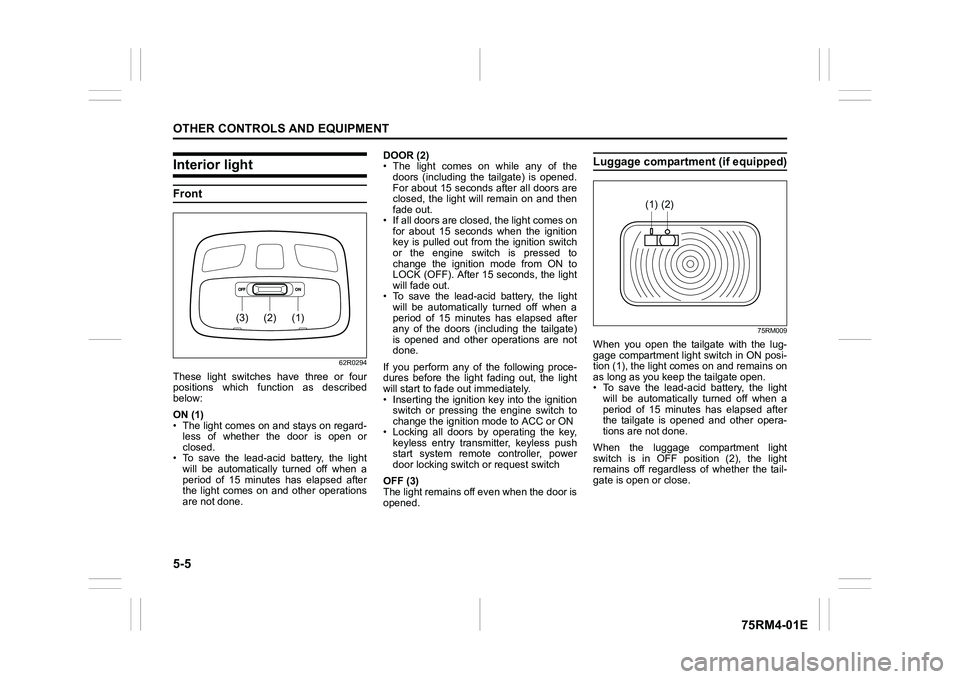
These light switches have three or four
positions which function as described
below:
ON (1)
• The light comes on and stays on regard-less of whether the door is open or
closed.
• To save the lead-acid battery, the light
will be automatically turned off when a
period of 15 minutes has elapsed after
the light comes on and other operations
are not done. DOOR (2)
• The light comes on while any of the
doors (including the tailgate) is opened.
For about 15 seconds after all doors are
closed, the light will remain on and then
fade out.
• If all doors are closed, the light comes on for about 15 seconds when the ignition
key is pulled out from the ignition switch
or the engine switch is pressed to
change the ignition mode from ON to
LOCK (OFF). After 15 seconds, the light
will fade out.
• To save the lead-acid battery, the light will be automatically turned off when a
period of 15 minutes has elapsed after
any of the doors (including the tailgate)
is opened and other operations are not
done.
If you perform any of the following proce-
dures before the light fading out, the light
will start to fade out immediately.
• Inserting the ignition key into the ignition switch or pressing the engine switch to
change the ignition mode to ACC or ON
• Locking all doors by operating the key, keyless entry transmitter, keyless push
start system remote controller, power
door locking switc h or request switch
OFF (3)
The light remains off even when the door is
opened.
Luggage compartment (if equipped)
75RM009
When you open the tailgate with the lug-
gage compartment light switch in ON posi-
tion (1), the light com es on and remains on
as long as you keep the tailgate open.
• To save the lead-acid battery, the light
will be automatically turned off when a
period of 15 minutes has elapsed after
the tailgate is opened and other opera-
tions are not done.
When the luggage compartment light
switch is in OFF position (2), the light
remains off regardless of whether the tail-
gate is open or close.
(1)
(2)
(3)
(2)
(1)
Page 372 of 505
7-23INSPECTION AND MAINTENANCE
75RM4-01E
Drive beltCheck that the drive belt tension is correct.
If the belt is too loose, insufficient battery
charging, engine overheating, poor power
steering, poor air conditioning, or exces-
sive belt wear can result. When you press
the belt with your thumb midway between
the pulleys, there should be a deflection
according to the following chart.
The belts should also be examined to
ensure that they are not damaged.
If you need to replace or adjust the belt
have it done by your SUZUKI dealer.K12C engine models
The drive belts tension is adjusted auto-
matically.
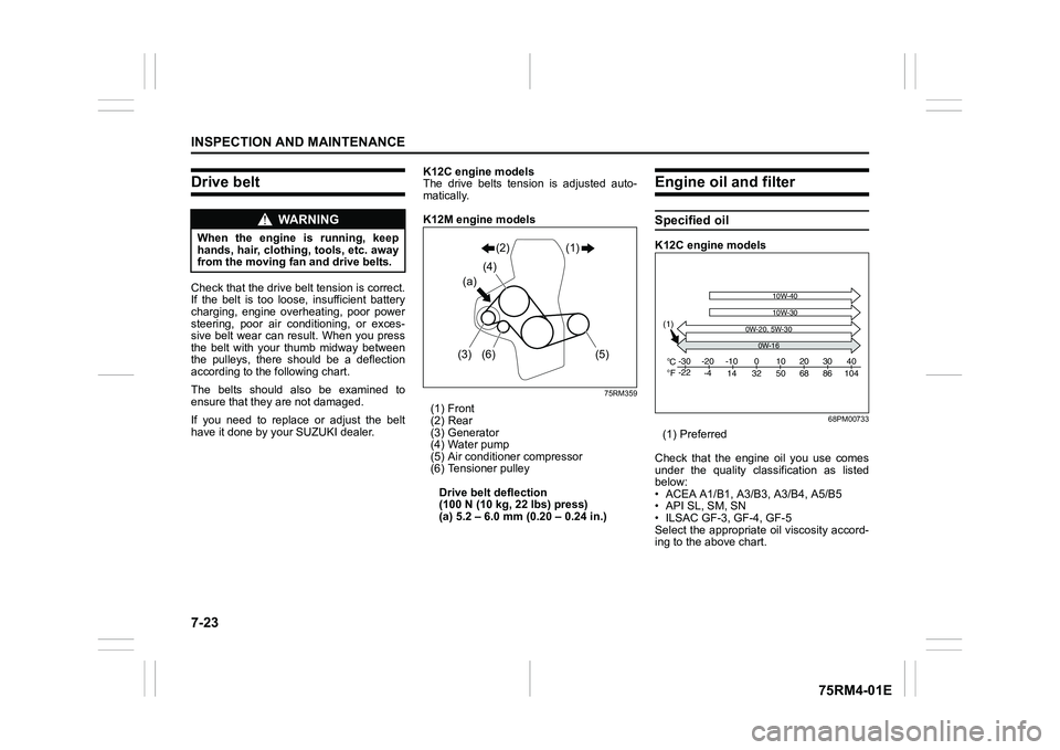
K12M engine models
75RM359
(1) Front
(2) Rear
(3) Generator
(4) Water pump
(5) Air conditioner compressor
(6) Tensioner pulley
Drive belt deflection
(100 N (10 kg, 22 lbs) press)
(a) 5.2 – 6.0 mm (0.20 – 0.24 in.)
Engine oil and filterSpecified oil K12C engine models
68PM00733
(1) Preferred
Check that the engine oil you use comes
under the quality classification as listed
below:
• ACEA A1/B1, A3/ B3, A3/B4, A5/B5
• API SL, SM, SN
• ILSAC GF-3, GF-4, GF-5
Select the appropriate oil viscosity accord-
ing to the above chart.
WA R N I N G
When the engine is running, keep
hands, hair, clothing, tools, etc. away
from the moving fan and drive belts.
(a) (4)(2) (1)
(3) (6) (5)
C Fo
o-30
-22
-20
10W-40
-4-10
14 32 50 68 86 104 010203040
10W-30
(1)
0W-20, 5W-30
0W-16