leak SUZUKI JIMNY 2005 3.G Service Owners Manual
[x] Cancel search | Manufacturer: SUZUKI, Model Year: 2005, Model line: JIMNY, Model: SUZUKI JIMNY 2005 3.GPages: 687, PDF Size: 13.38 MB
Page 537 of 687
Downloaded from www.Manualslib.com manuals search engine 6A1-56 ENGINE MECHANICAL (M13 ENGINE)
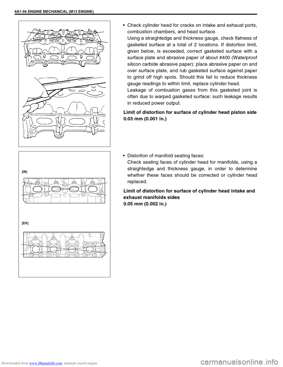
Check cylinder head for cracks on intake and exhaust ports,
combustion chambers, and head surface.
Using a straightedge and thickness gauge, check flatness of
gasketed surface at a total of 2 locations. If distortion limit,
given below, is exceeded, correct gasketed surface with a
surface plate and abrasive paper of about #400 (Waterproof
silicon carbide abrasive paper): place abrasive paper on and
over surface plate, and rub gasketed surface against paper
to grind off high spots. Should this fail to reduce thickness
gauge readings to within limit, replace cylinder head.
Leakage of combustion gases from this gasketed joint is
often due to warped gasketed surface: such leakage results
in reduced power output.
Limit of distortion for surface of cylinder head piston side
0.03 mm (0.001 in.)
Distortion of manifold seating faces:
Check seating faces of cylinder head for manifolds, using a
straightedge and thickness gauge, in order to determine
whether these faces should be corrected or cylinder head
replaced.
Limit of distortion for surface of cylinder head intake and
exhaust manifolds sides
0.05 mm (0.002 in.)
Page 538 of 687

Downloaded from www.Manualslib.com manuals search engine ENGINE MECHANICAL (M13 ENGINE) 6A1-57
Valve Springs
Referring to data given below, check to be sure that each
spring is in sound condition, free of any evidence of break-
age or weakening. Remember, weakened valve springs can
cause chatter, not to mention possibility of reducing power
output due to gas leakage caused by decreased seating
pressure.
Valve spring free length
Standard : 36.83 mm (1.450 in.)
Limit : 35.83 mm (1.410 in.)
Valve spring preload
Standard : 107 – 125 N (10.7 – 12.5 kg) for 31.5 mm
(23.6 – 27.6 lb / 1.240 in.)
Limit : 102 N (10.2 kg) for 31.5 mm (22.9 lb / 1.240 in.)
Spring skewness:
Use a square and surface plate to check each spring for
skewness in terms of clearance between end of valve spring
and square. Valve springs found to exhibit a larger clearance
than limit given below must be replaced.
Valve spring skewness
Limit : 1.6 mm (0.063 in.)
ASSEMBLY
1) Before installing valve guide into cylinder head, ream guide
hole with special tool (10.5 mm reamer) so as to remove
burrs and make it truly round.
Special tool
(A) : 09916-34542
(B) : 09916-37320
Page 542 of 687

Downloaded from www.Manualslib.com manuals search engine ENGINE MECHANICAL (M13 ENGINE) 6A1-61
6) Install exhaust manifold stiffener and exhaust pipe referring
to “Exhaust Manifold” in this section.
7) Install camshafts, timing chain and chain cover referring to
“Camshaft, Tappet and Shim”, “Timing Chain and Chain
Tensioner” and “Timing Chain Cover” in this section.
8) Install cylinder head cover and oil pan referring to “Cylinder
Head Cover” and “Oil Pan and Oil Pump Strainer” in this sec-
tion.
9) Install intake manifold stiffener and connect each hoses and
electric lead wires securely.
10) Install air cleaner outlet hoses.
11) Install radiator with cooling fan and connect A/T fluid hoses
(vehicle with A/T), radiator inlet and outlet hoses referring to
“Water Pump Belt and Cooling Fan” and “Radiator” in Sec-
tion 6B.
12) Adjust generator belt tension referring to “Water Pump Belt
Tension” in Section 6B.
13) Adjust A/C compressor and/or P/S pump belt tension (if
equipped) referring to “Compressor Drive Belt” in Section 1B
or “Power Steering Belt” in Section 3B1.
14) Adjust accelerator cable play referring to “Accelerator Cable
Adjustment” in Section 6E.
15) Check to ensure that all removed parts are back in place.
Reinstall any necessary parts which have not been rein-
stalled.
16) Refill cooling system with coolant, engine with engine oil and
A/T with specified A/T fluid (vehicle with A/T).
17) Connect negative cable at battery.
18) Verify that there is no fuel leakage, coolant leakage, oil leak-
age, A/T fluid leakage (vehicle with A/T) and exhaust gas
leakage at each connection.
Page 552 of 687
Downloaded from www.Manualslib.com manuals search engine ENGINE MECHANICAL (M13 ENGINE) 6A1-71
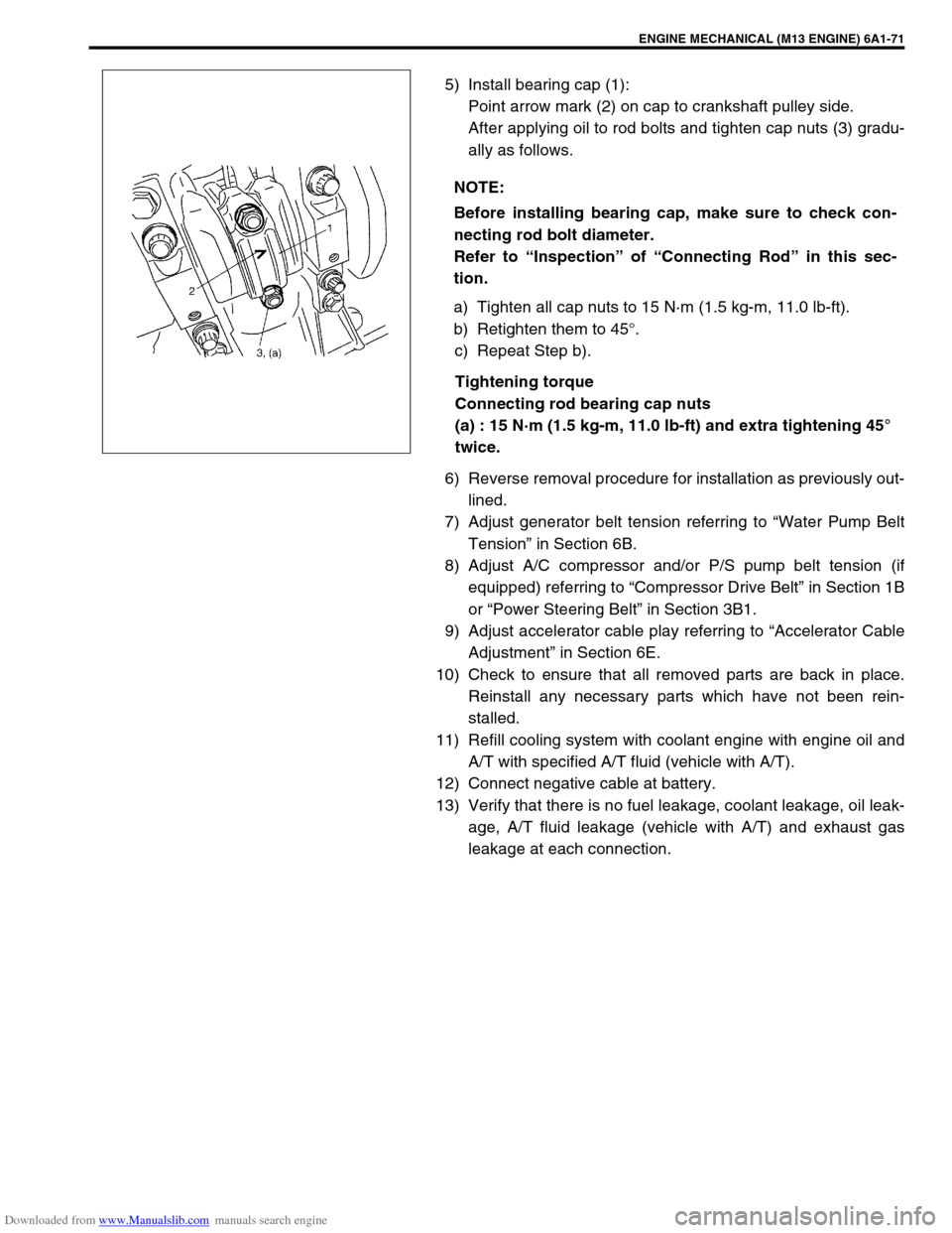
5) Install bearing cap (1):
Point arrow mark (2) on cap to crankshaft pulley side.
After applying oil to rod bolts and tighten cap nuts (3) gradu-
ally as follows.
a) Tighten all cap nuts to 15 N·m (1.5 kg-m, 11.0 lb-ft).
b) Retighten them to 45°.
c) Repeat Step b).
Tightening torque
Connecting rod bearing cap nuts
(a) : 15 N·m (1.5 kg-m, 11.0 lb-ft) and extra tightening 45°
twice.
6) Reverse removal procedure for installation as previously out-
lined.
7) Adjust generator belt tension referring to “Water Pump Belt
Tension” in Section 6B.
8) Adjust A/C compressor and/or P/S pump belt tension (if
equipped) referring to “Compressor Drive Belt” in Section 1B
or “Power Steering Belt” in Section 3B1.
9) Adjust accelerator cable play referring to “Accelerator Cable
Adjustment” in Section 6E.
10) Check to ensure that all removed parts are back in place.
Reinstall any necessary parts which have not been rein-
stalled.
11) Refill cooling system with coolant engine with engine oil and
A/T with specified A/T fluid (vehicle with A/T).
12) Connect negative cable at battery.
13) Verify that there is no fuel leakage, coolant leakage, oil leak-
age, A/T fluid leakage (vehicle with A/T) and exhaust gas
leakage at each connection. NOTE:
Before installing bearing cap, make sure to check con-
necting rod bolt diameter.
Refer to “Inspection” of “Connecting Rod” in this sec-
tion.
Page 559 of 687
Downloaded from www.Manualslib.com manuals search engine 6A1-78 ENGINE MECHANICAL (M13 ENGINE)
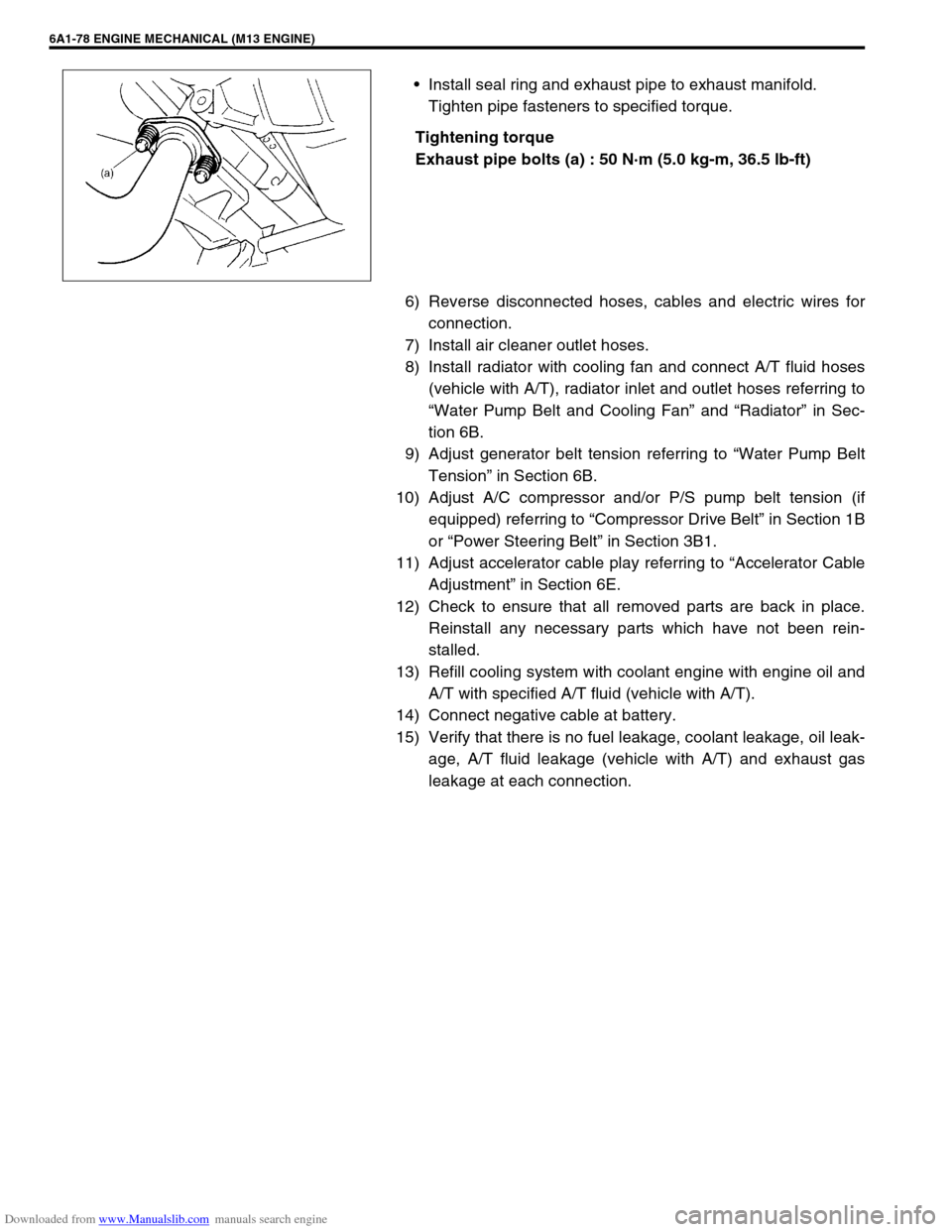
Install seal ring and exhaust pipe to exhaust manifold.
Tighten pipe fasteners to specified torque.
Tightening torque
Exhaust pipe bolts (a) : 50 N·m (5.0 kg-m, 36.5 lb-ft)
6) Reverse disconnected hoses, cables and electric wires for
connection.
7) Install air cleaner outlet hoses.
8) Install radiator with cooling fan and connect A/T fluid hoses
(vehicle with A/T), radiator inlet and outlet hoses referring to
“Water Pump Belt and Cooling Fan” and “Radiator” in Sec-
tion 6B.
9) Adjust generator belt tension referring to “Water Pump Belt
Tension” in Section 6B.
10) Adjust A/C compressor and/or P/S pump belt tension (if
equipped) referring to “Compressor Drive Belt” in Section 1B
or “Power Steering Belt” in Section 3B1.
11) Adjust accelerator cable play referring to “Accelerator Cable
Adjustment” in Section 6E.
12) Check to ensure that all removed parts are back in place.
Reinstall any necessary parts which have not been rein-
stalled.
13) Refill cooling system with coolant engine with engine oil and
A/T with specified A/T fluid (vehicle with A/T).
14) Connect negative cable at battery.
15) Verify that there is no fuel leakage, coolant leakage, oil leak-
age, A/T fluid leakage (vehicle with A/T) and exhaust gas
leakage at each connection.
Page 582 of 687

Downloaded from www.Manualslib.com manuals search engine ENGINE COOLING 6B-5
Diagnosis
Condition Possible Cause Correction
Engine overheats
Loose or broken water pump belt
Not enough coolant
Faulty thermostat
Faulty water pump
Dirty or bent radiator fins
Coolant leakage on cooling system
Defective cooling fan clutch
Plugged radiator
Faulty radiator cap
Maladjusted ignition timing
Dragging brakes
Slipping clutchAdjust or replace.
Check coolant level and add as
necessary.
Replace.
Replace.
Clean or remedy.
Repair.
Check and replace as necessary.
Check and replace radiator as
necessary.
Replace.
Check system related parts.
Adjust brake.
Adjust or replace.
Page 584 of 687
Downloaded from www.Manualslib.com manuals search engine ENGINE COOLING 6B-7
Coolant Level
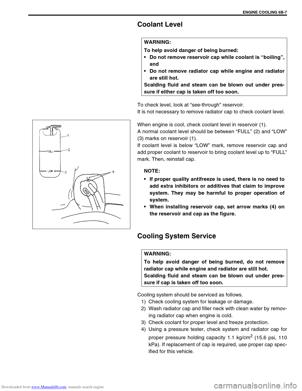
To check level, look at “see-through” reservoir.
It is not necessary to remove radiator cap to check coolant level.
When engine is cool, check coolant level in reservoir (1).
A normal coolant level should be between “FULL” (2) and “LOW”
(3) marks on reservoir (1).
If coolant level is below “LOW” mark, remove reservoir cap and
add proper coolant to reservoir to bring coolant level up to “FULL”
mark. Then, reinstall cap.
Cooling System Service
Cooling system should be serviced as follows.
1) Check cooling system for leakage or damage.
2) Wash radiator cap and filler neck with clean water by remov-
ing radiator cap when engine is cold.
3) Check coolant for proper level and freeze protection.
4) Using a pressure tester, check system and radiator cap for
proper pressure holding capacity 1.1 kg/cm
2 (15.6 psi, 110
kPa). If replacement of cap is required, use proper cap spec-
ified for this vehicle. WARNING:
To help avoid danger of being burned:
Do not remove reservoir cap while coolant is “boiling”,
and
Do not remove radiator cap while engine and radiator
are still hot.
Scalding fluid and steam can be blown out under pres-
sure if either cap is taken off too soon.
NOTE:
If proper quality antifreeze is used, there is no need to
add extra inhibitors or additives that claim to improve
system. They may be harmful to proper operation of
system.
When installing reservoir cap, set arrow marks (4) on
the reservoir and cap as the figure.
WARNING:
To help avoid danger of being burned, do not remove
radiator cap while engine and radiator are still hot.
Scalding fluid and steam can be blown out under pres-
sure if cap is taken off too soon.
Page 590 of 687

Downloaded from www.Manualslib.com manuals search engine ENGINE COOLING 6B-13
Water Pump Belt and Cooling Fan
REMOVAL
1) Remove radiator shroud securing bolts (1).
2) Remove radiator by referring to “Radiator” in this section.
3) Loosen water pump drive belt tension.
4) Remove cooling fan by removing securing nuts.
Remove power steering and/or compressor drive belt before
removing water pump belt.
5) Remove pump belt.
INSTALLATION
Once cooling fan or water pump belt has been removed, make
sure to tighten bolts and nuts securely in reinstallation and adjust
pump belt tension to specification. For specified tension, refer to
“Water Pump Belt Tension” in this section.
WATER PUMP BELT TENSION INSPECTION
1) Check belt tension. It should be within specification. Refer to
“Water Pump Belt Tension” in this section.
2) If tension is out of specification, adjust it.
For its adjustment, refer to “Water Pump Belt Tension” in this
section.
After adjustment, be sure to tighten bolts.
COOLING FAN CLUTCH INSPECTION
Inspect fluid coupling for oil leakage.
If necessary, replace fan clutch assembly. Do not disassemble
clutch assembly.
Page 591 of 687

Downloaded from www.Manualslib.com manuals search engine 6B-14 ENGINE COOLING
Radiator
REMOVAL
1) Drain cooling system.
2) Remove radiator shroud.
3) Disconnect water hoses from radiator.
4) With automatic transmission (A/T) vehicle, disconnect addi-
tional two fluid hoses from radiator.
Place some container under radiator to receive A/T fluid
which will flow out when hose is disconnected.
5) Install radiator protection board to between radiator and
cooling fan.
6) Remove radiator after removing two bolts (1).
INSPECTION
If the water side of the radiator is found excessively rusted or cov-
ered with scales, clean it by flushing with the radiator cleaner
compound.
This flushing should be carried out at regular intervals for scale or
rust formation advances with time even where a recommended
type of coolant is used. Periodical flushing will prove more eco-
nomical.
Inspect the radiator cores and straighten the flattened or bent
fins, if any. Clean the cores, removing road grimes and trashes.
Excessive rust or scale formation on the wet side of the radiator
lowers the cooling efficiency.
Flattened or bent fins obstruct the flow of air through the core to
impede heat dissipation.
Radiator flushing interval recommended
Two years
INSTALLATION
Reverse removal procedures.
NOTE:
Refill cooling system with proper coolant referring to
“Coolant” and “Cooling System Flush and Refill” in
this section.
With automatic transmission vehicle, fill A/T fluid up to
specified level. For procedure to check A/T fluid and its
level, refer to “Changing Fluid” in Section 7B.
After installation, check each joint for leakage.
Page 599 of 687
Downloaded from www.Manualslib.com manuals search engine 6C-4 ENGINE FUEL
On-Vehicle Service
Before work, refer to “Precaution on Fuel System Service” in Sec-
tion 6.
Fuel Lines
Due to the fact that fuel feed line is under high pressure, use spe-
cial care when servicing it.
INSPECTION
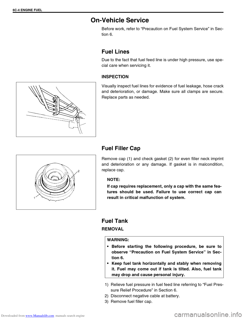
Visually inspect fuel lines for evidence of fuel leakage, hose crack
and deterioration, or damage. Make sure all clamps are secure.
Replace parts as needed.
Fuel Filler Cap
Remove cap (1) and check gasket (2) for even filler neck imprint
and deterioration or any damage. If gasket is in malcondition,
replace cap.
Fuel Tank
REMOVAL
1) Relieve fuel pressure in fuel feed line referring to “Fuel Pres-
sure Relief Procedure” in Section 6.
2) Disconnect negative cable at battery.
3) Remove fuel filler cap.
NOTE:
If cap requires replacement, only a cap with the same fea-
tures should be used. Failure to use correct cap can
result in critical malfunction of system.
WARNING:
Before starting the following procedure, be sure to
observe “Precaution on Fuel System Service” in Sec-
tion 6.
Keep fuel tank horizontally and stably when removing
it. Fuel may come out if tank is tilted. Also, fuel tank
may drop and cause personal injury.