check engine SUZUKI JIMNY 2005 3.G Service Workshop Manual
[x] Cancel search | Manufacturer: SUZUKI, Model Year: 2005, Model line: JIMNY, Model: SUZUKI JIMNY 2005 3.GPages: 687, PDF Size: 13.38 MB
Page 224 of 687

Downloaded from www.Manualslib.com manuals search engine REAR SUSPENSION 3E-5
Check wheel bearings for wear. When measuring thrust
play, apply a dial gauge to axle shaft center after removing
wheel center cap from wheel disc.
When measurement exceeds limit, replace bearing.
Rear wheel bearing thrust play limit
: 0.8 mm (0.03 in.)
By rotating wheel actually, check wheel bearing for noise and
smooth rotation. If it is defective, replace bearing.
On-Vehicle Service
Rear Shock Absorber
The shock absorber is non-adjustable, non-refillable, and cannot be disassembled. The only service the shock
absorber requires is replacement when it has lost its resistance, is damaged, or leaking fluid.
REMOVAL
1) Hoist vehicle.
2) Support rear axle housing (1) by using floor jack (2) to pre-
vent it from lowering.
WARNING:
When discarding shock absorber, be sure to refer to instructions in “Rear Shock Absorber Check” in
this section for proper procedure as it is gas sealed type.
Page 236 of 687
Downloaded from www.Manualslib.com manuals search engine REAR SUSPENSION 3E-17
16) Upon completion of all jobs, depress brake pedal with about
30 kg (66 lbs) load over ten times so as to obtain proper
drum-to shoe clearance.
Adjust parking brake cable. (For adjustment, refer to “Parking
Brake Check and Adjustment” in Section 5.)
17) Tighten parking brake lever cover screws.
18) Check to ensure that brake drum is free from dragging and
proper braking is obtained. Then remove vehicle from hoist
and perform brake test (foot brake and parking brake).
19) Check each installed part for oil leakage.
Rear Axle Shaft Inner Oil Seal
REMOVAL
1) Remove rear axle shaft. For details, refer to “Rear Axle Shaft
and Wheel Bearing” in this section.
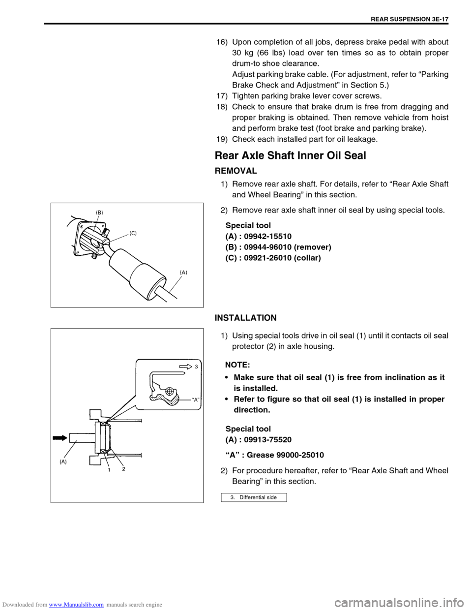
2) Remove rear axle shaft inner oil seal by using special tools.
Special tool
(A) : 09942-15510
(B) : 09944-96010 (remover)
(C) : 09921-26010 (collar)
INSTALLATION
1) Using special tools drive in oil seal (1) until it contacts oil seal
protector (2) in axle housing.
Special tool
(A) : 09913-75520
“A” : Grease 99000-25010
2) For procedure hereafter, refer to “Rear Axle Shaft and Wheel
Bearing” in this section.
NOTE:
Make sure that oil seal (1) is free from inclination as it
is installed.
Refer to figure so that oil seal (1) is installed in proper
direction.
3. Differential side
Page 240 of 687
Downloaded from www.Manualslib.com manuals search engine REAR SUSPENSION 3E-21
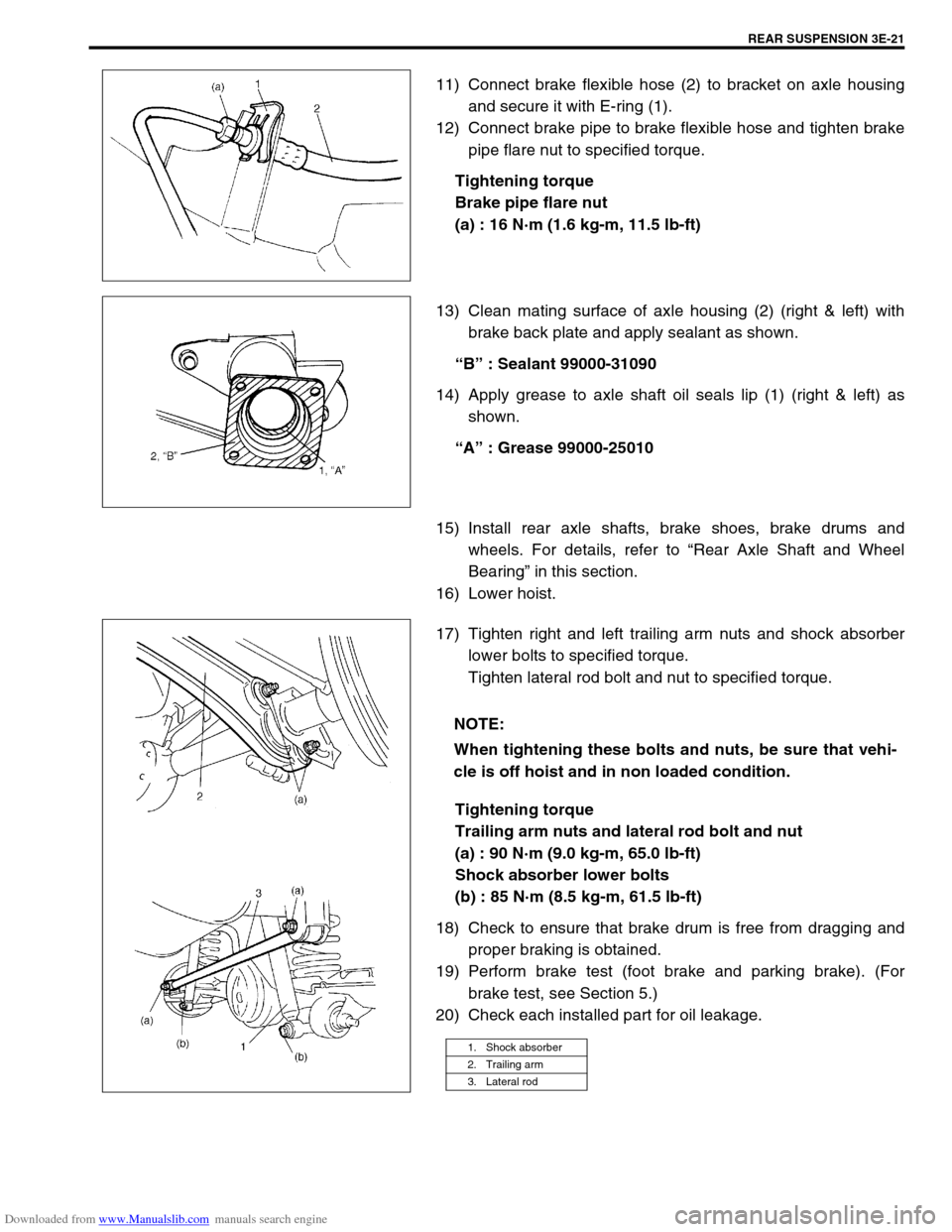
11) Connect brake flexible hose (2) to bracket on axle housing
and secure it with E-ring (1).
12) Connect brake pipe to brake flexible hose and tighten brake
pipe flare nut to specified torque.
Tightening torque
Brake pipe flare nut
(a) : 16 N·m (1.6 kg-m, 11.5 lb-ft)
13) Clean mating surface of axle housing (2) (right & left) with
brake back plate and apply sealant as shown.
“B” : Sealant 99000-31090
14) Apply grease to axle shaft oil seals lip (1) (right & left) as
shown.
“A” : Grease 99000-25010
15) Install rear axle shafts, brake shoes, brake drums and
wheels. For details, refer to “Rear Axle Shaft and Wheel
Bearing” in this section.
16) Lower hoist.
17) Tighten right and left trailing arm nuts and shock absorber
lower bolts to specified torque.
Tighten lateral rod bolt and nut to specified torque.
Tightening torque
Trailing arm nuts and lateral rod bolt and nut
(a) : 90 N·m (9.0 kg-m, 65.0 lb-ft)
Shock absorber lower bolts
(b) : 85 N·m (8.5 kg-m, 61.5 lb-ft)
18) Check to ensure that brake drum is free from dragging and
proper braking is obtained.
19) Perform brake test (foot brake and parking brake). (For
brake test, see Section 5.)
20) Check each installed part for oil leakage.
NOTE:
When tightening these bolts and nuts, be sure that vehi-
cle is off hoist and in non loaded condition.
1. Shock absorber
2. Trailing arm
3. Lateral rod
Page 249 of 687
Downloaded from www.Manualslib.com manuals search engine 3F-6 WHEELS AND TIRES
Maintenance and Minor Adjustments
Wheel and Tire
Wheel repairs that use welding, heating, or peening are not approved. All damaged wheels should be replaced.
Studs
If a broken stud is found, see Section 3E (rear) or Section 3D (front) for Note and Replacement procedure.
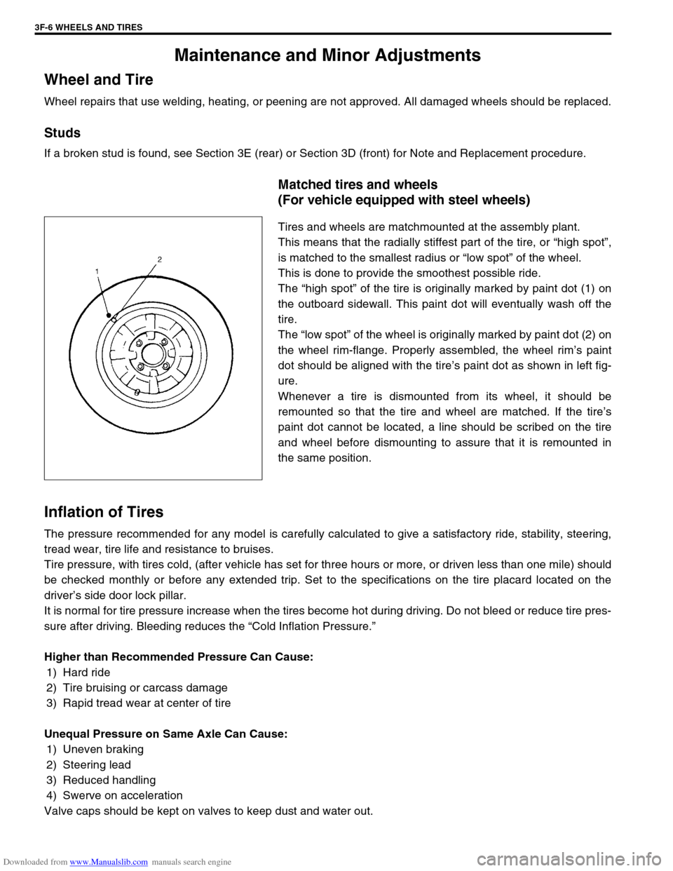
Matched tires and wheels
(For vehicle equipped with steel wheels)
Tires and wheels are matchmounted at the assembly plant.
This means that the radially stiffest part of the tire, or “high spot”,
is matched to the smallest radius or “low spot” of the wheel.
This is done to provide the smoothest possible ride.
The “high spot” of the tire is originally marked by paint dot (1) on
the outboard sidewall. This paint dot will eventually wash off the
tire.
The “low spot” of the wheel is originally marked by paint dot (2) on
the wheel rim-flange. Properly assembled, the wheel rim’s paint
dot should be aligned with the tire’s paint dot as shown in left fig-
ure.
Whenever a tire is dismounted from its wheel, it should be
remounted so that the tire and wheel are matched. If the tire’s
paint dot cannot be located, a line should be scribed on the tire
and wheel before dismounting to assure that it is remounted in
the same position.
Inflation of Tires
The pressure recommended for any model is carefully calculated to give a satisfactory ride, stability, steering,
tread wear, tire life and resistance to bruises.
Tire pressure, with tires cold, (after vehicle has set for three hours or more, or driven less than one mile) should
be checked monthly or before any extended trip. Set to the specifications on the tire placard located on the
driver’s side door lock pillar.
It is normal for tire pressure increase when the tires become hot during driving. Do not bleed or reduce tire pres-
sure after driving. Bleeding reduces the “Cold Inflation Pressure.”
Higher than Recommended Pressure Can Cause:
1) Hard ride
2) Tire bruising or carcass damage
3) Rapid tread wear at center of tire
Unequal Pressure on Same Axle Can Cause:
1) Uneven braking
2) Steering lead
3) Reduced handling
4) Swerve on acceleration
Valve caps should be kept on valves to keep dust and water out.
Page 254 of 687
Downloaded from www.Manualslib.com manuals search engine PROPELLER SHAFTS 4B-1
6F1
6F2
6G
6H
6K
7A
7A1
7B1
7C1
7D
4B
8D
8E
9
8E
9
10
10A
10B
SECTION 4B
PROPELLER SHAFTS
CONTENTS
General Description ....................................... 4B-2
Components ................................................. 4B-2
Diagnosis ........................................................ 4B-2
Diagnosis Table ........................................... 4B-2
Propeller Shaft Joint Check .......................... 4B-2
On-Vehicle Service......................................... 4B-3Propeller Shafts ........................................... 4B-3
Universal Joint ............................................. 4B-5
Tightening Torque Specification .................. 4B-7
Required Service Material ............................. 4B-7
Special Tool .................................................... 4B-8
NOTE:
All propeller shaft fasteners are an important attaching part in that it could affect the performance
of vital parts and systems, and/or could result in major repair expense. They must be replaced with
one of the same part number or with an equivalent part if replacement becomes necessary. Do not
use a replacement part of lesser quality or substitute design. Torque values must be used as speci-
fied during reassembly to assure proper retention of this part.
Never attempt to heat, quench or straighten any propeller shaft part. Replace it with a new part, or
damage to the part may result.
Page 255 of 687
Downloaded from www.Manualslib.com manuals search engine 4B-2 PROPELLER SHAFTS
General Description
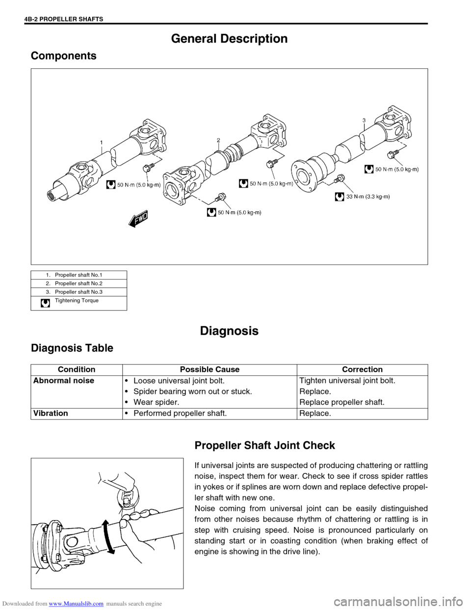
Components
Diagnosis
Diagnosis Table
Propeller Shaft Joint Check
If universal joints are suspected of producing chattering or rattling
noise, inspect them for wear. Check to see if cross spider rattles
in yokes or if splines are worn down and replace defective propel-
ler shaft with new one.
Noise coming from universal joint can be easily distinguished
from other noises because rhythm of chattering or rattling is in
step with cruising speed. Noise is pronounced particularly on
standing start or in coasting condition (when braking effect of
engine is showing in the drive line).
1. Propeller shaft No.1
2. Propeller shaft No.2
3. Propeller shaft No.3
Tightening Torque
Condition Possible Cause Correction
Abnormal noise
Loose universal joint bolt.
Spider bearing worn out or stuck.
Wear spider.Tighten universal joint bolt.
Replace.
Replace propeller shaft.
Vibration
Performed propeller shaft. Replace.
Page 262 of 687
Downloaded from www.Manualslib.com manuals search engine BRAKES 5-1
6F1
6F2
6G
6H
6K
7A
7A1
7B1
7C1
7D
7E
5
9
10
10A
10B
9
10
10A
10B
SECTION 5
BRAKES
CONTENTS
General Description ......................................... 5-3
Diagnosis .......................................................... 5-4
Road Testing Brakes ...................................... 5-4
Brake Fluid Leaks .......................................... 5-4
Substandard or Contaminated Brake Fluid .... 5-4
Diagnosis Table ............................................. 5-5
Brake Pedal Free Height Adjustment ............. 5-8
Brake Pedal Play Check ................................ 5-8
Stop Light Switch Adjustment ........................ 5-8
Excessive Pedal Travel Check ....................... 5-9
Front Brake Disc Check ................................. 5-9
Front Brake Pad Check .................................. 5-9
Rear Brake Shoe Check .............................. 5-10
Master Cylinder and Brake Fluid Level
Check ........................................................... 5-10
Rear Drum Brake Shoe Adjustment ............. 5-11
Parking Brake Inspection and Adjustment ... 5-11
Booster Operation Check ............................. 5-12Fluid Pressure Test
(If Equipped with LSPV) ............................... 5-15
On-Vehicle Service ........................................ 5-17
Air Bleeding of Brake System ...................... 5-17
Brake Hose and Pipe Inspection.................. 5-18
Front Disc Brake .......................................... 5-19
Brake pad ................................................. 5-20
Caliper assembly...................................... 5-22
Brake Disc.................................................... 5-26
Rear Brake ................................................... 5-29
Brake drum............................................... 5-29
Brake shoe ............................................... 5-32
Wheel Cylinder............................................. 5-33
Brake back plate ...................................... 5-34
Master Cylinder .............................................. 5-36
Master Cylinder Reservoir ........................... 5-36
Master Cylinder Assembly ........................... 5-37 WARNING:
For lifting point of vehicle, refer to Section 0A.
WARNING:
For vehicles equipped with Supplement Restraint (Air Bag) System:
Service on and around the air bag system components or wiring must be performed only by an
authorized SUZUKI dealer. Refer to “Air Bag System Components and Wiring Location View” under
“General Description” in air bag system section in order to confirm whether you are performing ser-
vice on or near the air bag system components or wiring. Please observe all WARNINGS and “Ser-
vice Precautions” under “On-Vehicle Service” in air bag system section before performing service
on or around the air bag system components or wiring. Failure to follow WARNINGS could result in
unintentional activation of the system or could render the system inoperative. Either of these two
conditions may result in severe injury.
Technical service work must be started at least 90 seconds after the ignition switch is turned to the
“LOCK” position and the negative cable is disconnected from the battery. Otherwise, the system
may be activated by reserve energy in the Sensing and Diagnostic Module (SDM).
NOTE:
When inspecting and servicing vehicle equipped with ABS, be sure to refer to section 5E first.
All brake fasteners are important attaching parts in that they could affect the performance of vital
parts and systems, and/or could result in major repair expense. They must be replaced with one of
same part number or with an equivalent part if replacement becomes necessary. Do not use a
replacement part of lesser quality or substitute design. Torque values must be used as specified
during reassembly to assure proper retention of all parts. There is to be no welding as it may result
in extensive damage and weakening of the metal.
Page 265 of 687

Downloaded from www.Manualslib.com manuals search engine 5-4 BRAKES
Diagnosis
Road Testing Brakes
Brakes should be tested on dry, clean, smooth and reasonably level roadway which is not crowned. Road test
brakes by making brake applications with both light and heavy pedal forces at various speeds to determine if the
vehicle stops evenly and effectively.
Also drive vehicle to see if it leads to one side or the other without brake application. If it does, check the tire
pressure, front end alignment and front suspension attachments for looseness. See diagnosis table for other
causes.
Brake Fluid Leaks
Check the master cylinder fluid levels. While a slight drop in reservoir level does result from normal lining wear,
an abnormally low level indicates a leak in the system. In such a case, check the entire brake system for leak-
age. If even a slight evidence of leakage is noted, the cause should be corrected or defective parts should be
replaced.
If fluid level is lower than the minimum level of reservoir, refilling is necessary. Fill reservoir with specified brake
fluid.
Brake fluid: Refer to reservoir tank cap.
Substandard or Contaminated Brake Fluid
Improper brake fluid, mineral oil or water in the fluid may cause the brake fluid to boil or the rubber components
in the hydraulic system to deteriorate.
If primary piston cups are swollen, then rubber parts have deteriorated. This deterioration may also be evi-
denced by swollen wheel cylinder piston cups on the drum brake wheels.
If deterioration of rubber is evident, disassemble all hydraulic parts and wash with alcohol. Dry these parts with
compressed air before assembly to keep alcohol out of the system. Replace all rubber parts in the system,
including hoses. Also, when working on the brake mechanisms, check for fluid on the linings. If excessive fluid is
found, replace the linings.
If master cylinder piston seals are satisfactory, check for leakage or excessive heat conditions. If condition is not
found, drain fluid, flush with brake fluid, refill and bleed the system.
The system must be flushed if there is any doubt as to the grade of fluid in the system or if fluid has been used
which contained parts that have been subjected to contaminated fluid.CAUTION:
Since brake system of this vehicle is factory-filled with brake fluid indicated on reservoir tank cap, do
not use or mix different type of fluid when refilling; otherwise serious damage will occur.
Do not use old or used brake fluid, or any fluid from a unsealed container.
Page 266 of 687

Downloaded from www.Manualslib.com manuals search engine BRAKES 5-5
Diagnosis Table
Condition Possible Cause Correction
Not enough braking
forceBrake oil leakage from brake lines Locate leaking point and repair.
Brake disc or pads stained with oil Clean or replace.
Overheated brakes Determine cause and repair.
Poor contact of shoes on brake drum Repair for proper contact.
Brake shoes linings stained with oil or wet with
waterReplace.
Badly worn brake shoe linings Replace.
Defective wheel cylinders Repair or replace.
Malfunctioning caliper assembly Repair or replace.
Air in system Bleed system.
Maladjusted sensor spring length of LSPV Check or adjust.
Broken sensor spring of LSPV Replace.
Defective collar of LSPV Replace.
Malfunctioning ABS (Antilock brake system), if
equippedCheck system and replace as nec-
essary.
Brake pull (Brakes not
working in unison)Pad or shoe linings are wet with water or
stained with oil in some brakesReplace.
Drum-to-shoe clearance out of adjustment in
some brakes (Malfunctioning auto adjusting
mechanism)Check for inoperative auto adjusting
mechanism.
Drum is out of round in some brakes Replace.
Wheel tires are inflated unequally Inflate equally.
Malfunctioning wheel cylinders Repair or replace.
Disturbed front wheel alignment Adjust as prescribed.
Unmatched tires on same axle Tires with approximately the same
amount of tread should be used on
the same axle.
Restricted brake tubes or hoses Check for soft hoses and damaged
lines.
Replace with new hoses and new
double-walled steel brake tubing.
Malfunctioning caliper assembly Check for stuck or sluggish pistons
and proper lubrication of caliper
slide bush.
Loose suspension parts Caliper should slide.
Check all suspension mountings.
Loose calipers Check and torque bolts to specifica-
tions.
Noise (high pitched
squeak without brake
applied)Front lining worn out Replace brake pads.
Rear brake locked pre-
maturelyMaladjusted sensor spring length of LSPV Check or adjust.
Malfunctioning LSPV assembly Replace assembly.
Brake locked
(For vehicles
equipped with ABS)Malfunctioning ABS, if equipped Check system and replace as nec-
essary.
Page 267 of 687

Downloaded from www.Manualslib.com manuals search engine 5-6 BRAKES
Excessive pedal travel
(Pedal stroke too
large)Partial brake system failure Check brake systems and repair as
necessary.
Insufficient fluid in master cylinder reservoirs Fill reservoirs with approved brake
fluid.
Check for leaks and air in brake
systems.
Check warning light. Bleed system
if required.
Air in system (pedal soft/spongy) Bleed system.
Rear brake system not adjusted (malfunctioning
auto adjusting mechanism)Repair auto adjusting mechanism.
Adjust rear brakes.
Bent brake shoes Replace brake shoes.
Worn rear brake shoes Replace brake shoes.
Dragging brakes (A
very light drag is
present in all disc
brakes immediately
after pedal is released)Master cylinder pistons not returning correctly Repair master cylinder.
Restricted brake tubes or hoses Check for soft hoses or damaged
tubes and replace with new hoses
and/or new brake tubes.
Incorrect parking brake adjustment on rear
brakesCheck and adjust to correct specifi-
cations.
Weakened or broken return springs in the brake Replace.
Sluggish parking-brake cables or linkage Repair or replace.
Wheel cylinder or caliper piston sticking Repair as necessary.
Malfunctioning ABS, if equipped with ABS Check system and replace as nec-
essary.
Pedal pulsation (Pedal
pulsates when
depressed for brak-
ing.) Damaged or loose wheel bearings Replace wheel bearings.
Distorted steering knuckle or rear axle shafts Replace knuckle or rear axle shaft.
Excessive disc lateral runout Check per instructions. If not within
specifications, replace or machine
the disc.
Parallelism not within specifications Check per instructions. If not with
specifications, replace or machine
the disc.
Rear drums out of round. Check runout.
Repair or replace drum as neces-
sary.
Braking noise
Glazed shoe linings, or foreign matters stuck to
liningsRepair or replace brake shoe.
Worn or distorted shoe linings Replace brake shoe (or pad).
Loose front wheel bearings Replace wheel bearing.
Distorted backing plates or loose mounting
boltsReplace or retighten securing bolts.
Brake warning light
turns on after engine
startParking brake applied Release parking brake and check
that brake warning light turns off.
Insufficient amount of brake fluid Add brake fluid.
Brake fluid leaking from brake line Investigate leaky point, correct it
and add brake fluid.
Brake warning light circuit faulty Repair circuit. Condition Possible Cause Correction