check engine SUZUKI JIMNY 2005 3.G Service Workshop Manual
[x] Cancel search | Manufacturer: SUZUKI, Model Year: 2005, Model line: JIMNY, Model: SUZUKI JIMNY 2005 3.GPages: 687, PDF Size: 13.38 MB
Page 303 of 687
Downloaded from www.Manualslib.com manuals search engine 5-42 BRAKES
LSPV (Load Sensing Proportioning Valve) Assembly (If Equipped)
REMOVAL
1) Clean around reservoir cap and take out fluid with syringe or
such.
2) Hoist vehicle.
3) Disconnect brake pipes from LSPV.
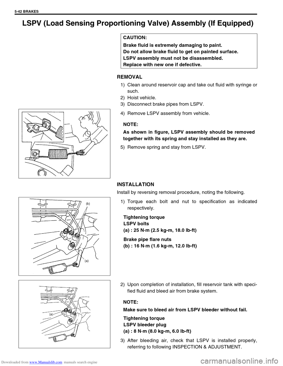
4) Remove LSPV assembly from vehicle.
5) Remove spring and stay from LSPV.
INSTALLATION
Install by reversing removal procedure, noting the following.
1) Torque each bolt and nut to specification as indicated
respectively.
Tightening torque
LSPV bolts
(a) : 25 N·m (2.5 kg-m, 18.0 lb-ft)
Brake pipe flare nuts
(b) : 16 N·m (1.6 kg-m, 12.0 lb-ft)
2) Upon completion of installation, fill reservoir tank with speci-
fied fluid and bleed air from brake system.
Tightening torque
LSPV bleeder plug
(a) : 8 N·m (8.0 kg-m, 6.0 lb-ft)
3) After bleeding air, check that LSPV is installed properly,
referring to following INSPECTION & ADJUSTMENT. CAUTION:
Brake fluid is extremely damaging to paint.
Do not allow brake fluid to get on painted surface.
LSPV assembly must not be disassembled.
Replace with new one if defective.
NOTE:
As shown in figure, LSPV assembly should be removed
together with its spring and stay installed as they are.
NOTE:
Make sure to bleed air from LSPV bleeder without fail.
Page 304 of 687
Downloaded from www.Manualslib.com manuals search engine BRAKES 5-43
LSPV Assembly
INSPECTION AND ADJUSTMENT
1) Confirm the following before inspection and adjustment.
Fuel tank is filled with fuel fully.
Vehicle is equipped with spare tire, tools, jack and jack han-
dle.
Vehicle is free from any other load.
Place it on level floor.
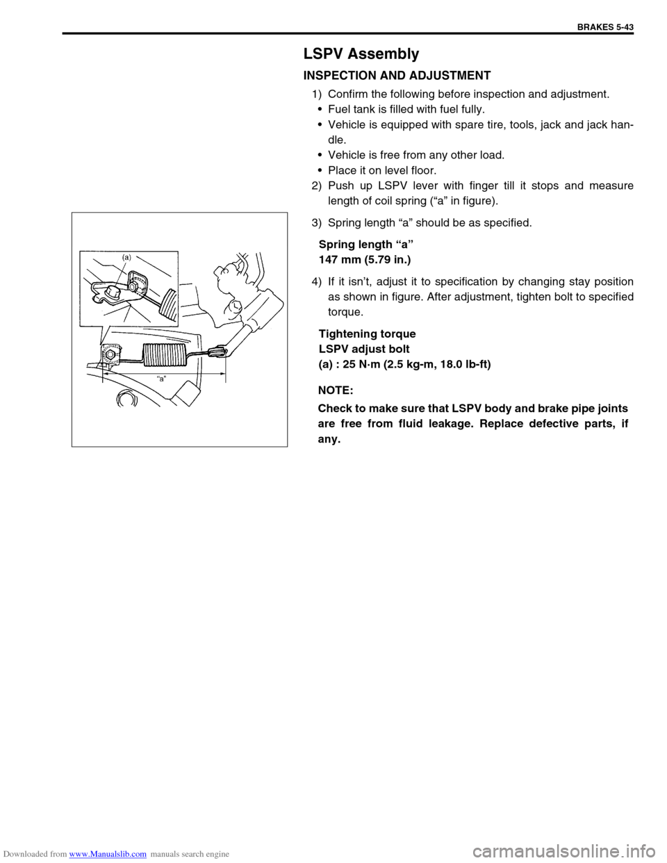
2) Push up LSPV lever with finger till it stops and measure
length of coil spring (“a” in figure).
3) Spring length “a” should be as specified.
Spring length “a”
147 mm (5.79 in.)
4) If it isn’t, adjust it to specification by changing stay position
as shown in figure. After adjustment, tighten bolt to specified
torque.
Tightening torque
LSPV adjust bolt
(a) : 25 N·m (2.5 kg-m, 18.0 lb-ft)
NOTE:
Check to make sure that LSPV body and brake pipe joints
are free from fluid leakage. Replace defective parts, if
any.
Page 307 of 687
Downloaded from www.Manualslib.com manuals search engine 5-46 BRAKES
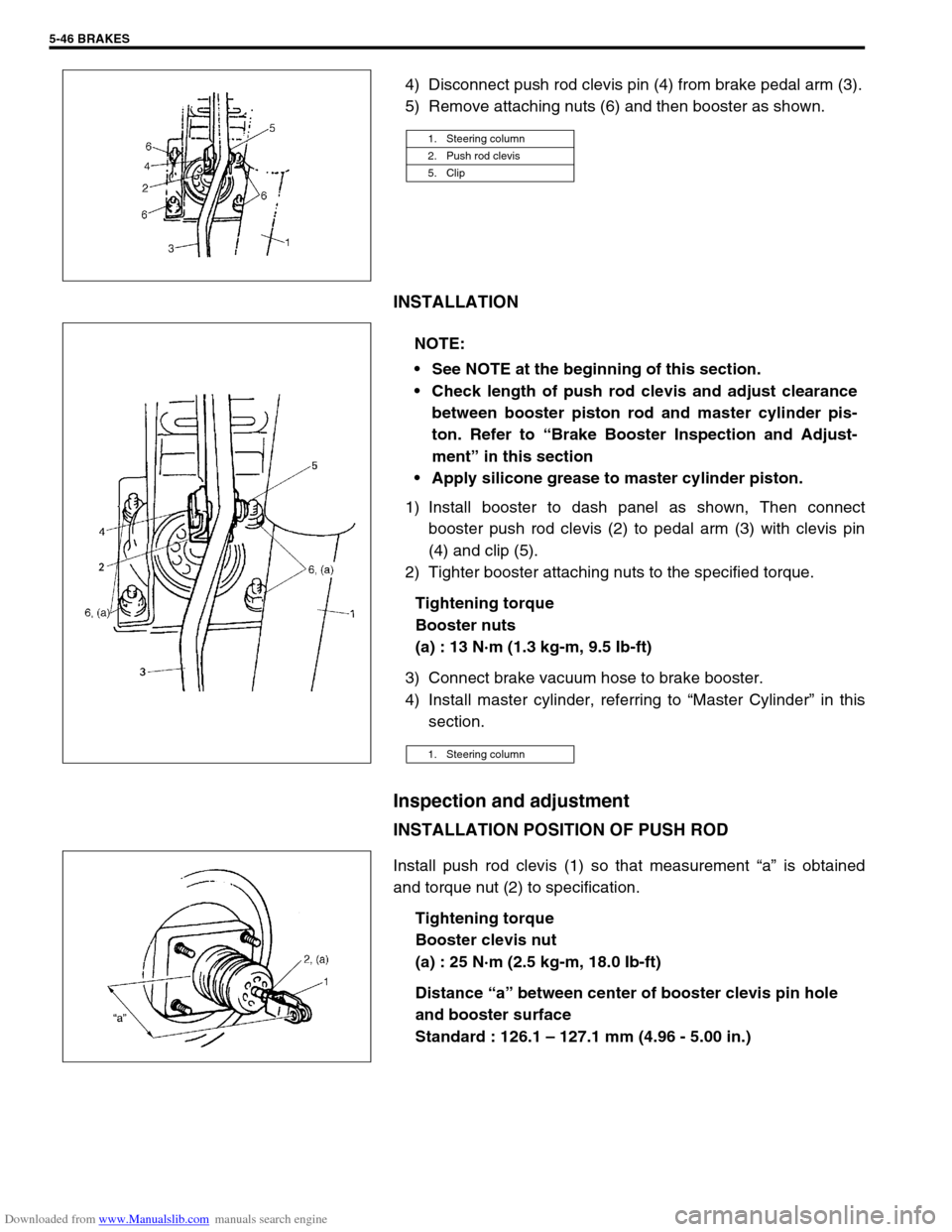
4) Disconnect push rod clevis pin (4) from brake pedal arm (3).
5) Remove attaching nuts (6) and then booster as shown.
INSTALLATION
1) Install booster to dash panel as shown, Then connect
booster push rod clevis (2) to pedal arm (3) with clevis pin
(4) and clip (5).
2) Tighter booster attaching nuts to the specified torque.
Tightening torque
Booster nuts
(a) : 13 N·m (1.3 kg-m, 9.5 Ib-ft)
3) Connect brake vacuum hose to brake booster.
4) Install master cylinder, referring to “Master Cylinder” in this
section.
Inspection and adjustment
INSTALLATION POSITION OF PUSH ROD
Install push rod clevis (1) so that measurement “a” is obtained
and torque nut (2) to specification.
Tightening torque
Booster clevis nut
(a) : 25 N·m (2.5 kg-m, 18.0 Ib-ft)
Distance “a” between center of booster clevis pin hole
and booster surface
Standard : 126.1 – 127.1 mm (4.96 - 5.00 in.)
1. Steering column
2. Push rod clevis
5. Clip
NOTE:
See NOTE at the beginning of this section.
Check length of push rod clevis and adjust clearance
between booster piston rod and master cylinder pis-
ton. Refer to “Brake Booster Inspection and Adjust-
ment” in this section
Apply silicone grease to master cylinder piston.
1. Steering column
Page 311 of 687

Downloaded from www.Manualslib.com manuals search engine 5-50 BRAKES
REMOVAL
1) Raise, suitably support vehicle. Remove wheel if necessary.
2) Clean dirt and foreign material from both hose end or pipe end fittings. Remove brake hose and pipe.
INSTALLATION
1) Install brake hose and pipe by reversing removal procedure, noting the following points.
For installation, make sure that steering wheel is in straightforward position and hose has no twist or kink.
Check to make sure that hose doesn’t contact any part of suspension, both in extreme right and extreme left
turn conditions. If it does at any point, remove and correct. Fill and maintain brake fluid level in reservoir.
Bleed brake system.
2) Perform brake test and check installed part for fluid leakage.
Page 312 of 687
Downloaded from www.Manualslib.com manuals search engine BRAKES 5-51
Rear Brake Hose/Pipe
REMOVAL
1) Raise, suitably support vehicle. Remove wheel if necessary.
2) Clean dirt and foreign material from both hose end or pipe end fittings. Remove brake hose and pipe.
INSTALLATION
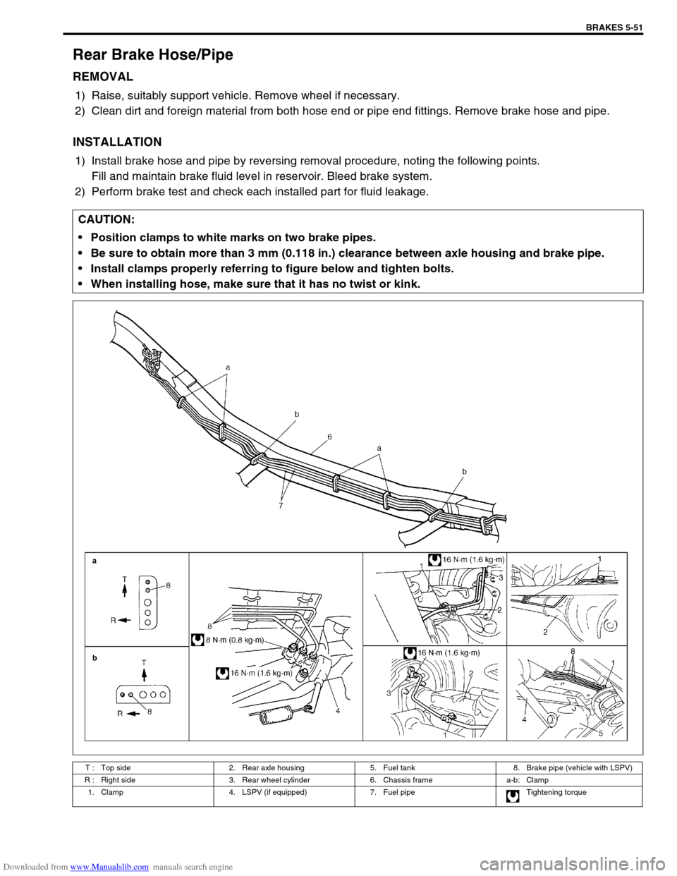
1) Install brake hose and pipe by reversing removal procedure, noting the following points.
Fill and maintain brake fluid level in reservoir. Bleed brake system.
2) Perform brake test and check each installed part for fluid leakage.
CAUTION:
Position clamps to white marks on two brake pipes.
Be sure to obtain more than 3 mm (0.118 in.) clearance between axle housing and brake pipe.
Install clamps properly referring to figure below and tighten bolts.
When installing hose, make sure that it has no twist or kink.
T : Top side 2. Rear axle housing 5. Fuel tank 8. Brake pipe (vehicle with LSPV)
R : Right side 3. Rear wheel cylinder 6. Chassis frame a-b: Clamp
1. Clamp 4. LSPV (if equipped) 7. Fuel pipe Tightening torque
Page 313 of 687
Downloaded from www.Manualslib.com manuals search engine 5-52 BRAKES
Parking Brake Lever/Cable
Parking brake lever
REMOVAL
1) Hoist vehicle and release parking brake lever.
2) Disconnect negative cable at battery.
3) Remove parking brake lever cover.
4) Disconnect lead wire of parking brake switch at coupler.
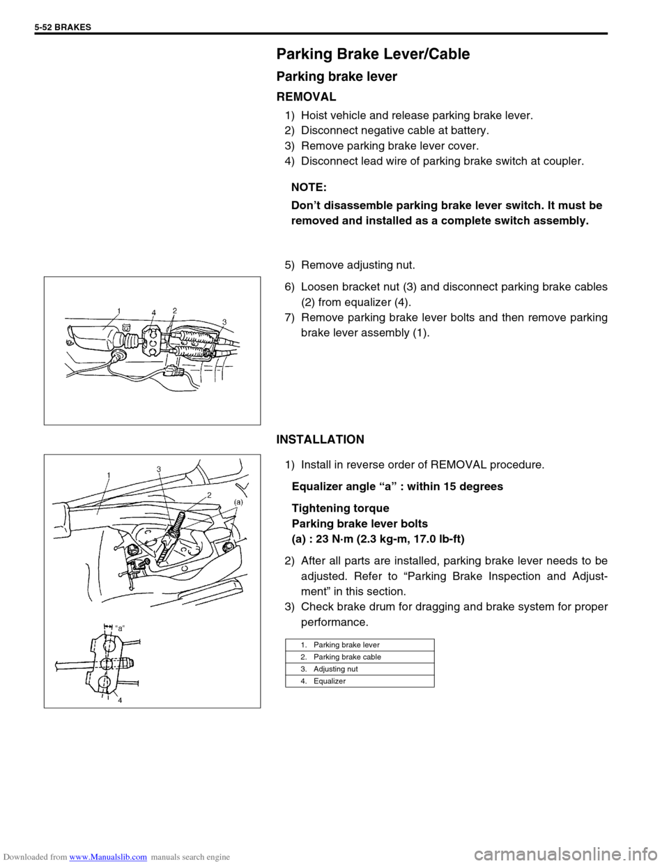
5) Remove adjusting nut.
6) Loosen bracket nut (3) and disconnect parking brake cables
(2) from equalizer (4).
7) Remove parking brake lever bolts and then remove parking
brake lever assembly (1).
INSTALLATION
1) Install in reverse order of REMOVAL procedure.
Equalizer angle “a” : within 15 degrees
Tightening torque
Parking brake lever bolts
(a) : 23 N·m (2.3 kg-m, 17.0 lb-ft)
2) After all parts are installed, parking brake lever needs to be
adjusted. Refer to “Parking Brake Inspection and Adjust-
ment” in this section.
3) Check brake drum for dragging and brake system for proper
performance. NOTE:
Don’t disassemble parking brake lever switch. It must be
removed and installed as a complete switch assembly.
1. Parking brake lever
2. Parking brake cable
3. Adjusting nut
4. Equalizer
Page 314 of 687
Downloaded from www.Manualslib.com manuals search engine BRAKES 5-53
Parking Brake Cable
REMOVAL
1) Raise, suitably support vehicle and remove wheel if necessary.
2) Remove parking brake cable.
INSTALLATION
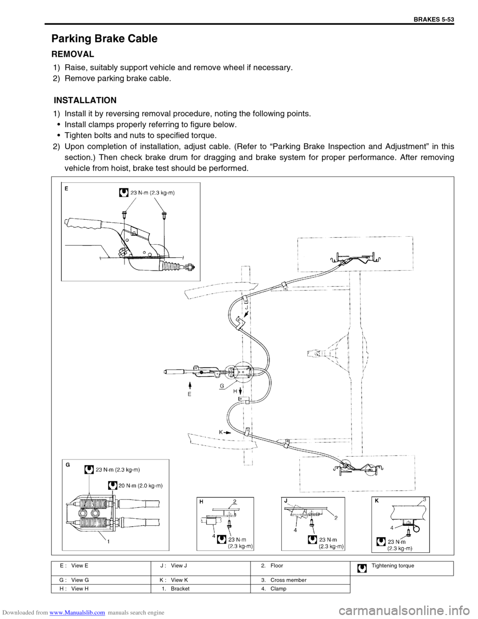
1) Install it by reversing removal procedure, noting the following points.
Install clamps properly referring to figure below.
Tighten bolts and nuts to specified torque.
2) Upon completion of installation, adjust cable. (Refer to “Parking Brake Inspection and Adjustment” in this
section.) Then check brake drum for dragging and brake system for proper performance. After removing
vehicle from hoist, brake test should be performed.
E : View E J : View J 2. Floor Tightening torque
G : View G K : View K 3. Cross member
H : View H 1. Bracket 4. Clamp
Page 318 of 687

Downloaded from www.Manualslib.com manuals search engine ANTILOCK BRAKE SYSTEM (ABS) 5E-1
6F1
6F2
6G
6H
6K
7A
7A1
7B1
7C1
7D
7E
7F
8E
5E
9
10
10A
10B
10
10A
10B
SECTION 5E
ANTILOCK BRAKE SYSTEM (ABS)
CONTENTS
General Description ....................................... 5E-2
System Schematic ....................................... 5E-3
ABS Component Parts Location .................. 5E-4
ABS Control Module ..................................... 5E-5
Self-diagnosis function ............................. 5E-5
Fail-safe function ...................................... 5E-5
Diagnosis ........................................................ 5E-6
Precaution in Diagnosing Troubles .............. 5E-6
ABS Diagnostic Flow Table .......................... 5E-6
“ABS” Warning Lamp Check ........................ 5E-9
Diagnostic Trouble Code (DTC) Check ........ 5E-9
DTC Check (Using SUZUKI Scan Tool) ..... 5E-10
Diagnostic Trouble Code (DTC)
Clearance ................................................... 5E-10
Diagnostic Trouble Code (DTC) Table ....... 5E-11
System Circuit ............................................ 5E-12
Table – A “ABS” Warning Lamp Circuit
Check – Lamp Does Not Come “ON”
at Ignition Switch ON .................................. 5E-14
Table – B “ABS” Warning Lamp Circuit
Check – Lamp Comes “ON” Steady ........... 5E-15
Table – C “ABS” Warning Lamp Circuit
Check – Lamp Flashes Continuously
While Ignition Switch is ON ........................ 5E-16
Table – D Code (DTC) is Not Outputted
Even With Diag. Switch Terminal
Connected to Ground. ................................ 5E-17
DTC C1015 (DTC 15) – G Sensor
Circuit ......................................................... 5E-18
DTC C1016 (DTC 16) – Stop Lamp
Circuit ......................................................... 5E-20
DTC C1021 (DTC 21), DTC C1022
(DTC 22) – Right Front Wheel Speed
Sensor Circuit ............................................. 5E-21
DTC C1025 (DTC 25), DTC C1026
(DTC 26) – Left Front Wheel Speed
Sensor Circuit ............................................. 5E-21DTC C1031 (DTC 31), DTC C1032
(DTC 32) – Right Rear Wheel Speed
Sensor Circuit ............................................ 5E-21
DTC C1035 (DTC 35), DTC C1036
(DTC 36) – Left Rear Wheel Speed
Sensor Circuit ............................................ 5E-21
DTC C1041 (DTC 41), DTC C1042
(DTC 42) – Right Front Solenoid Circuit .... 5E-24
DTC C1045 (DTC 45), DTC C1046
(DTC 46) – Left Front Solenoid Circuit....... 5E-24
DTC C1055 (DTC 55), DTC C1056
(DTC 56) – Rear Solenoid Circuit .............. 5E-24
DTC C1057 (DTC 57) – Power Source
Circuit ......................................................... 5E-25
DTC C1061 (DTC 61) – ABS Pump
Motor Circuit............................................... 5E-26
DTC C1063 (DTC 63) – ABS Fail Safe
Circuit ......................................................... 5E-27
DTC C1071 (DTC 71) – ABS Control
Module ....................................................... 5E-28
On-Vehicle Service ...................................... 5E-29
Precaution .................................................. 5E-29
ABS Hydraulic Unit Operation Check ........ 5E-29
ABS Hydraulic Unit / Control Module
Assembly ................................................... 5E-30
Front Wheel Speed Sensor........................ 5E-32
Front Wheel Sensor Ring........................... 5E-35
Rear Wheel Speed Sensor ........................ 5E-36
Rear Wheel Sensor Ring ........................... 5E-38
G Sensor .................................................... 5E-39
Tightening Torque Specification ................ 5E-40
Special Tool .................................................. 5E-40 NOTE:
All brake fasteners are important attaching parts in that they could affect the performance of vital
parts and systems, and/or could result in major repair expense. They must be replaced with one of
same part number or with an equivalent part if replacement part of lesser quality or substitute design.
Torque values must be used as specified during reassembly to assure proper retention of all parts.
There is to be no welding as it may result in extensive damage and weakening of the metal.
Page 322 of 687
Downloaded from www.Manualslib.com manuals search engine ANTILOCK BRAKE SYSTEM (ABS) 5E-5
ABS Control Module
Self-diagnosis function
ABS control module diagnoses conditions of the system compo-
nent parts (whether or not there is any abnormality) all the time
and indicates the results (warning of abnormality occurrence and
DTC) through the “ABS” warning lamp as described below.
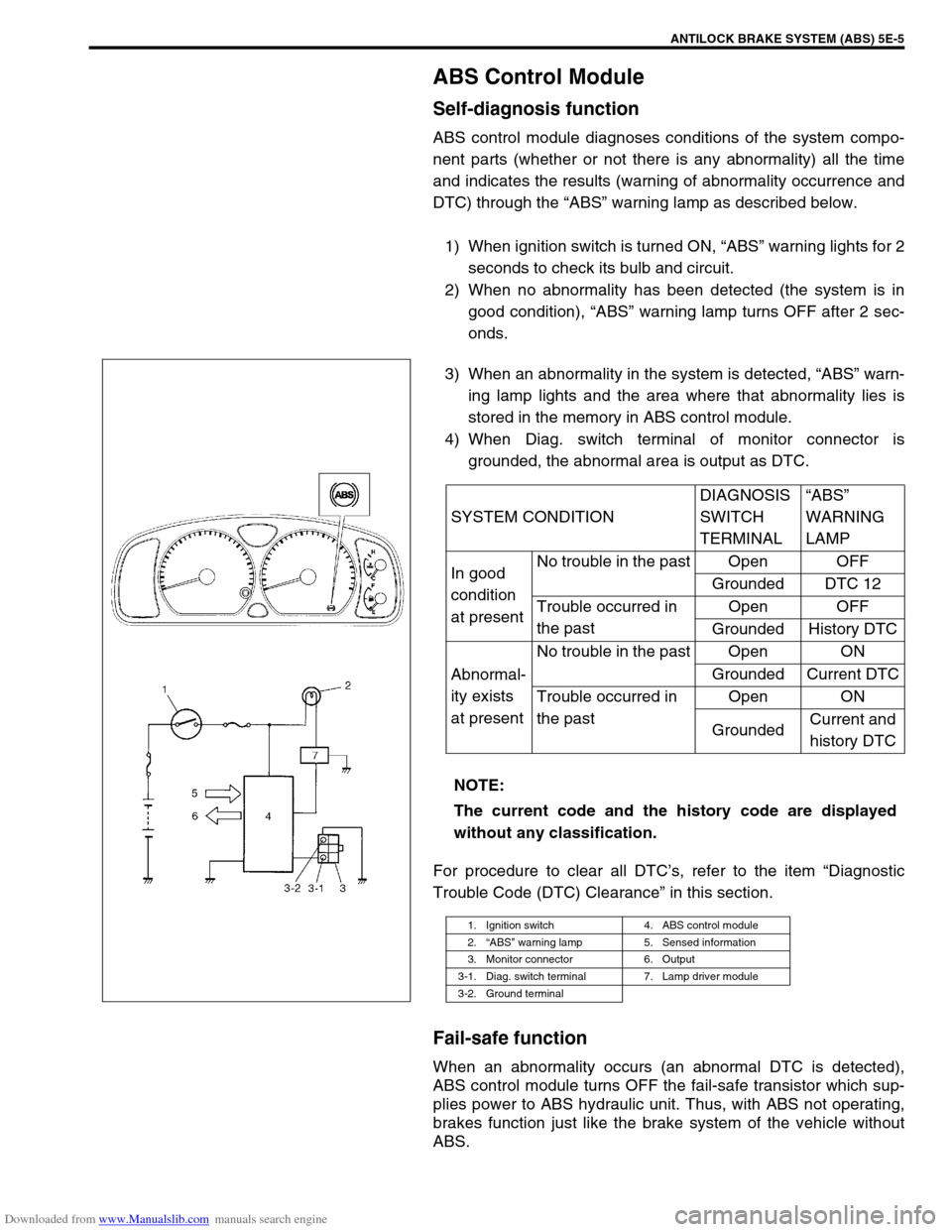
1) When ignition switch is turned ON, “ABS” warning lights for 2
seconds to check its bulb and circuit.
2) When no abnormality has been detected (the system is in
good condition), “ABS” warning lamp turns OFF after 2 sec-
onds.
3) When an abnormality in the system is detected, “ABS” warn-
ing lamp lights and the area where that abnormality lies is
stored in the memory in ABS control module.
4) When Diag. switch terminal of monitor connector is
grounded, the abnormal area is output as DTC.
For procedure to clear all DTC’s, refer to the item “Diagnostic
Trouble Code (DTC) Clearance” in this section.
Fail-safe function
When an abnormality occurs (an abnormal DTC is detected),
ABS control module turns OFF the fail-safe transistor which sup-
plies power to ABS hydraulic unit. Thus, with ABS not operating,
brakes function just like the brake system of the vehicle without
ABS.SYSTEM CONDITIONDIAGNOSIS
SWITCH
TERMINAL“ABS”
WARNING
LAMP
In good
condition
at presentNo trouble in the past Open OFF
Grounded DTC 12
Trouble occurred in
the pastOpen OFF
Grounded History DTC
Abnormal-
ity exists
at presentNo trouble in the past Open ON
Grounded Current DTC
Trouble occurred in
the pastOpen ON
GroundedCurrent and
history DTC
NOTE:
The current code and the history code are displayed
without any classification.
1. Ignition switch 4. ABS control module
2.“ABS” warning lamp 5. Sensed information
3. Monitor connector 6. Output
3-1. Diag. switch terminal 7. Lamp driver module
3-2. Ground terminal
Page 323 of 687

Downloaded from www.Manualslib.com manuals search engine 5E-6 ANTILOCK BRAKE SYSTEM (ABS)
Diagnosis
To ensure that the trouble diagnosis is done accurately and smoothly, observe “Precautions in Diagnosing Trou-
bles” and follow “ABS Diagnostic Flow Table”.
Precaution in Diagnosing Troubles
If the vehicles was operated in any of the following ways, “ABS” warning lamp may light momentarily but this
does not indicate anything abnormal in ABS.
–The vehicle was driven with parking brake pulled.
–The vehicle was driven with brake dragging.
–The vehicle was stuck in mud, sand, etc.
–Wheel spin occurred while driving.
–Wheel(s) was rotated while the vehicle was jacked up.
Be sure to read “Precautions for Electronic Circuit Service” in Section 0A before inspection and observe
what is written there.
Be sure to use the trouble diagnosis procedure as described in the flow table. Failure to follow the flow table
may result in incorrect diagnosis. Some other diag. trouble code may be stored by mistake in the memory of
ABS control module during inspection.
ABS Diagnostic Flow Table
Refer to the following for the details of each step.
Step Action Yes No
1 Perform customer complaint analysis, problem symptom confir-
mation and diagnostic trouble code check record and clear-
ance.
Is there any trouble code?Go to Step 2. Go to Step 5.
2 Perform driving test.
Is trouble symptom identified?Go to Step 3. Go to Step 6.
3 Check diagnostic trouble code.
Is it malfunction code?Go to Step 4. Go to Step 5.
4 Inspect and repair referring to applicable diagnostic trouble
code table in this section. Then perform final confirmation test
after clearing diagnostic trouble code.
Is trouble recur?Go to Step 7. End.
5 Inspect and repair referring to “Diagnosis Table” in Section 5.
Then perform final confirmation test after clearing diagnostic
trouble code.
Is trouble recur?Go to Step 7. End.
6 Check for intermittent problems referring to “Intermittent and
Poor Connection” in Section 0A and related circuit of trouble
code recorded in Step 3. Then perform final confirmation test
after clearing diagnostic trouble code.
Is trouble recur?Go to Step 7. End.
7 Perform diagnostic trouble code check record and clearance.
Is there any trouble code?Go to Step 4. Go to Step 5.