torque SUZUKI JIMNY 2005 3.G Service Workshop Manual
[x] Cancel search | Manufacturer: SUZUKI, Model Year: 2005, Model line: JIMNY, Model: SUZUKI JIMNY 2005 3.GPages: 687, PDF Size: 13.38 MB
Page 356 of 687
Downloaded from www.Manualslib.com manuals search engine ANTILOCK BRAKE SYSTEM (ABS) 5E-39
G Sensor
REMOVAL
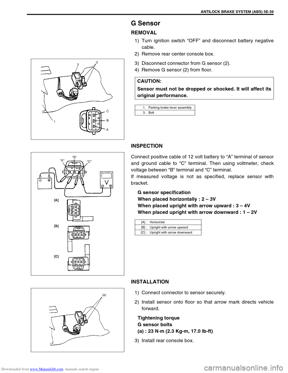
1) Turn ignition switch “OFF” and disconnect battery negative
cable.
2) Remove rear center console box.
3) Disconnect connector from G sensor (2).
4) Remove G sensor (2) from floor.
INSPECTION
Connect positive cable of 12 volt battery to “A” terminal of sensor
and ground cable to “C” terminal. Then using voltmeter, check
voltage between “B” terminal and “C” terminal.
If measured voltage is not as specified, replace sensor with
bracket.
G sensor specification
When placed horizontally : 2 – 3V
When placed upright with arrow upward : 3 – 4V
When placed upright with arrow downward : 1 – 2V
INSTALLATION
1) Connect connector to sensor securely.
2) Install sensor onto floor so that arrow mark directs vehicle
forward.
Tightening torque
G sensor bolts
(a) : 23 N·m (2.3 Kg-m, 17.0 lb-ft)
3) Install rear console box.CAUTION:
Sensor must not be dropped or shocked. It will affect its
original performance.
1. Parking brake lever assembly
3. Bolt
[A] : Horizontal
[B] : Upright with arrow upward
[C] : Upright with arrow downward
Page 357 of 687
Downloaded from www.Manualslib.com manuals search engine 5E-40 ANTILOCK BRAKE SYSTEM (ABS)
Tightening Torque Specification
Special Tool
Fastening partTightening torque
Nm kg-m lb-ft
Brake pipe flare nuts 16 1.6 11.6
ABS hydraulic unit / control module assembly bracket bolts 11 1.1 8.0
ABS hydraulic unit / control module assembly bolts 9 0.9 6.5
Front wheel speed sensor bolt 10 1.0 7.2
Front wheel speed sensor harness clamp bolts 10 1.0 7.2
Rear wheel speed sensor bolt 10 1.0 7.2
Rear wheel speed sensor harness clamp bolts 10 1.0 7.2
G sensor bolts 23 2.3 17.0
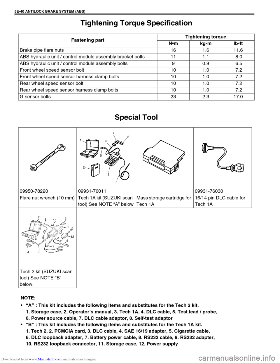
09950-78220 09931-76011 09931-76030
Flare nut wrench (10 mm) Tech 1A kit (SUZUKI scan
tool) See NOTE “A” belowMass storage cartridge for
Tech 1A16/14 pin DLC cable for
Tech 1A
Tech 2 kit (SUZUKI scan
tool) See NOTE “B”
below.
NOTE:
“A” : This kit includes the following items and substitutes for the Tech 2 kit.
1. Storage case, 2. Operator’s manual, 3. Tech 1A, 4. DLC cable, 5. Test lead / probe,
6. Power source cable, 7. DLC cable adaptor, 8. Self-test adaptor
“B” : This kit includes the following items and substitutes for the Tech 1A kit.
1. Tech 2, 2. PCMCIA card, 3. DLC cable, 4. SAE 16/19 adapter, 5. Cigarette cable,
6. DLC loopback adapter, 7. Battery power cable, 8. RS232 cable, 9. RS232 adapter,
10. RS232 loopback connector, 11. Storage case, 12. Power supply
Page 361 of 687
Downloaded from www.Manualslib.com manuals search engine 6-4 ENGINE GENERAL INFORMATION AND DIAGNOSIS
Precaution on fuel system service
Work must be done with no smoking, in a well-ventilated
area and away from any open flames.
As fuel feed line (between fuel pump and fuel delivery pipe)
is still under high fuel pressure even after engine was
stopped, loosening or disconnecting fuel feed line directly
may cause dangerous spout of fuel to occur where loosened
or disconnected.
Before loosening or disconnecting fuel feed line, make sure
to release fuel pressure according to “FUEL PRESSURE
RELIEF PROCEDURE”. A small amount of fuel may be
released after the fuel line is disconnected. In order to
reduce the chance of personal injury, cover the fitting to be
disconnected with a shop cloth. Put that cloth in an approved
container when disconnection is completed.
Never run engine with fuel pump relay disconnected when
engine and exhaust system are hot.
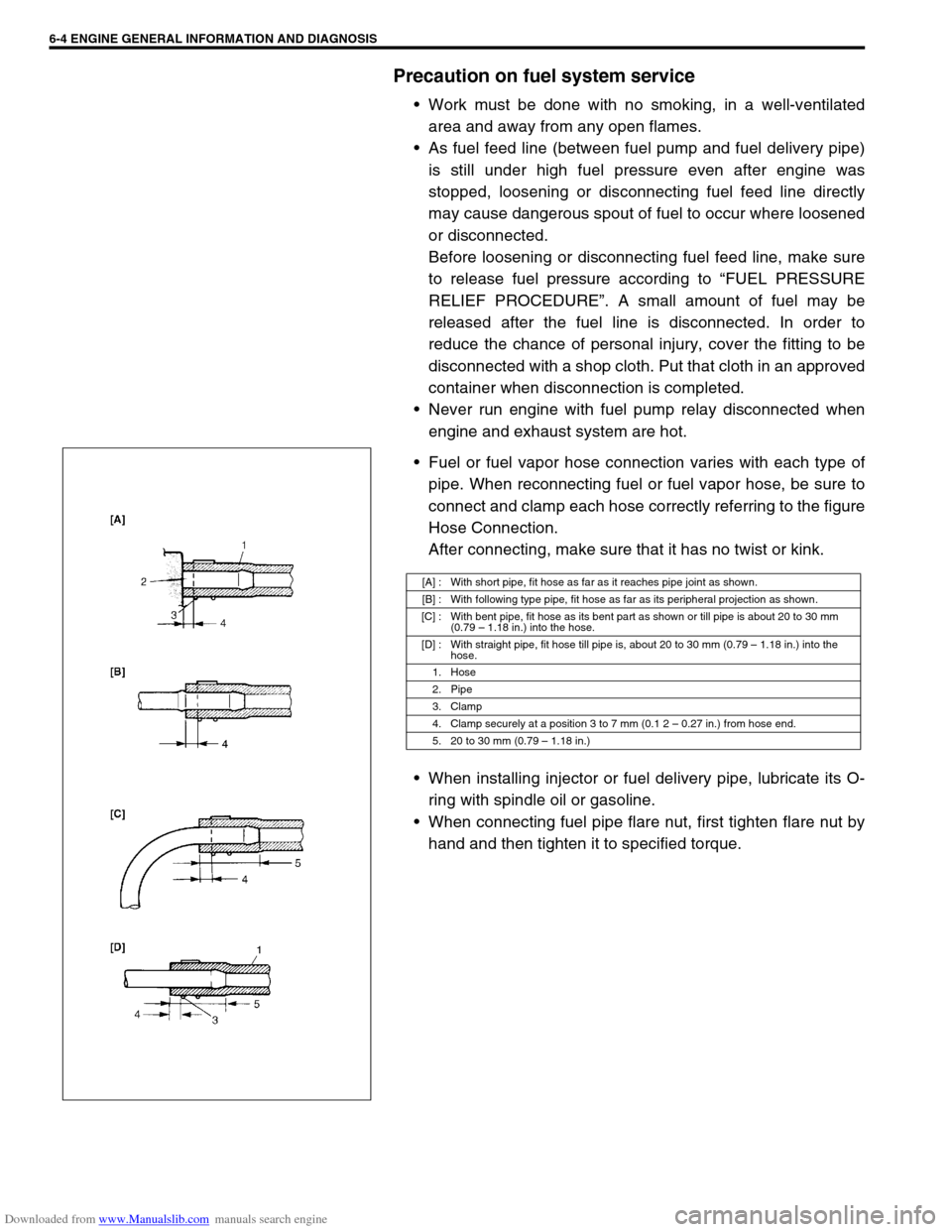
Fuel or fuel vapor hose connection varies with each type of
pipe. When reconnecting fuel or fuel vapor hose, be sure to
connect and clamp each hose correctly referring to the figure
Hose Connection.
After connecting, make sure that it has no twist or kink.
When installing injector or fuel delivery pipe, lubricate its O-
ring with spindle oil or gasoline.
When connecting fuel pipe flare nut, first tighten flare nut by
hand and then tighten it to specified torque.
[A] : With short pipe, fit hose as far as it reaches pipe joint as shown.
[B] : With following type pipe, fit hose as far as its peripheral projection as shown.
[C] : With bent pipe, fit hose as its bent part as shown or till pipe is about 20 to 30 mm
(0.79 – 1.18 in.) into the hose.
[D] : With straight pipe, fit hose till pipe is, about 20 to 30 mm (0.79 – 1.18 in.) into the
hose.
1. Hose
2. Pipe
3. Clamp
4. Clamp securely at a position 3 to 7 mm (0.1 2 – 0.27 in.) from hose end.
5. 20 to 30 mm (0.79 – 1.18 in.)
Page 375 of 687

Downloaded from www.Manualslib.com manuals search engine 6-18 ENGINE GENERAL INFORMATION AND DIAGNOSIS
DTC NO. DETECTING ITEM DETECTING CONDITION
(DTC will set when detecting :)MIL
P0702 Transmission Control System Electrical
Refer to Section 7B.
These DTCs can not be read on vehicle without
Immobilizer indicator lamp (by ECM application of
SUZUKI scan tool). P0705 Temperature Sensor Circuit Malfunction
P0710Transmission Temperature Sensor Circuit Mal-
function
P0715Input / Turbine Speed Sensor Circuit Malfunc-
tion
P0720Output Shaft Speed Sensor Circuit Malfunc-
tion
P0725 Engine Speed Input Circuit Malfunction
P0730 Incorrect Gear Ratio
P0743 Torque Converter Clutch Circuit Electrical
P0753 Shift Solenoid A Electrical
P0758 Shift Solenoid B Electrical
P0763 Shift Solenoid C Electrical
P0768 Shift Solenoid D Electrical
P1700 Throttle Position Signal Input Malfunction
P1702Internal Control Module Memory Check Some
Error
P1709Engine Coolant Temperature Signal Input
Malfunction
P1887 Transfer Signal
P1620
(No.84)ECU code not registered
Refer to Section 8G. P1621
(No.83)No ECU code transmitted from Immobilizer
Control Module
P1622
(No.82)Faulty in ECM
P1623
(No.81)ECU code not matched
NOTE:
For ( ) marked No. in DTC column, it is used for vehicle without Immobilizer indicator lamp.
DTC No.12 appears when none of the other codes is identified (vehicle without Immobilizer indica-
tor lamp).
Page 482 of 687
Downloaded from www.Manualslib.com manuals search engine ENGINE MECHANICAL (M13 ENGINE) 6A1-1
6F1
6G
6H
6K
7A
7A1
7B1
7C1
7D
7E
7F
8A
8C
6A1
8E
9
9
10B
SECTION 6A1
ENGINE MECHANICAL (M13 ENGINE)
CONTENTS
General Description ......................................6A1-2
Engine ......................................................... 6A1-2
Engine Lubrication ...................................... 6A1-3
Diagnosis .......................................................6A1-4
Diagnosis Table .......................................... 6A1-4
Compression Check .................................... 6A1-4
Engine Vacuum Check ................................ 6A1-6
Oil Pressure Check ..................................... 6A1-7
Valve Lash (Clearance) ............................... 6A1-9
On-Vehicle Service......................................6A1-13
Air Cleaner Element .................................. 6A1-13
Air Cleaner Assembly ................................ 6A1-14
Knock Sensor ............................................ 6A1-14
Cylinder Head Cover ................................. 6A1-15
Throttle Body and Intake Manifold ............ 6A1-18
Exhaust Manifold ....................................... 6A1-21Oil Pan and Oil Pump Strainer .................. 6A1-24
Timing Chain Cover .................................. 6A1-28
Oil Pump ................................................... 6A1-33
Timing Chain and Chain Tensioner .......... 6A1-37
Camshaft, Tappet and Shim ..................... 6A1-42
Valves and Cylinder Head ........................ 6A1-48
Pistons, Piston Rings, Connecting
Rods and Cylinders................................... 6A1-62
Engine Mountings ..................................... 6A1-72
Unit Repair Overhaul .................................. 6A1-73
Engine Assembly ...................................... 6A1-73
Main Bearings, Crankshaft and Cylinder
Block ......................................................... 6A1-79
Required Service Material .......................... 6A1-93
Tightening Torque Specification ............... 6A1-93
Special Tool ................................................. 6A1-94
WARNING:
For vehicles equipped with Supplemental Restraint (Air Bag) System:
Service on and around the air bag system components or wiring must be performed only by an
authorized SUZUKI dealer. Refer to “Air Bag System Components and Wiring Location View” under
“General Description” in air bag system section in order to confirm whether you are performing ser-
vice on or near the air bag system components or wiring. Please observe all WARNINGS and “Ser-
vice Precautions” under “On-Vehicle Service” in air bag system section before performing service
on or around the air bag system components or wiring. Failure to follow WARNINGS could result in
unintentional activation of the system or could render the system inoperative. Either of these two
conditions may result in severe injury.
Technical service work must be started at least 90 seconds after the ignition switch is turned to the
“LOCK” position and the negative cable is disconnected from the battery. Otherwise, the system
may be activated by reserve energy in the Sensing and Diagnostic Module (SDM).
Page 489 of 687
Downloaded from www.Manualslib.com manuals search engine 6A1-8 ENGINE MECHANICAL (M13 ENGINE)
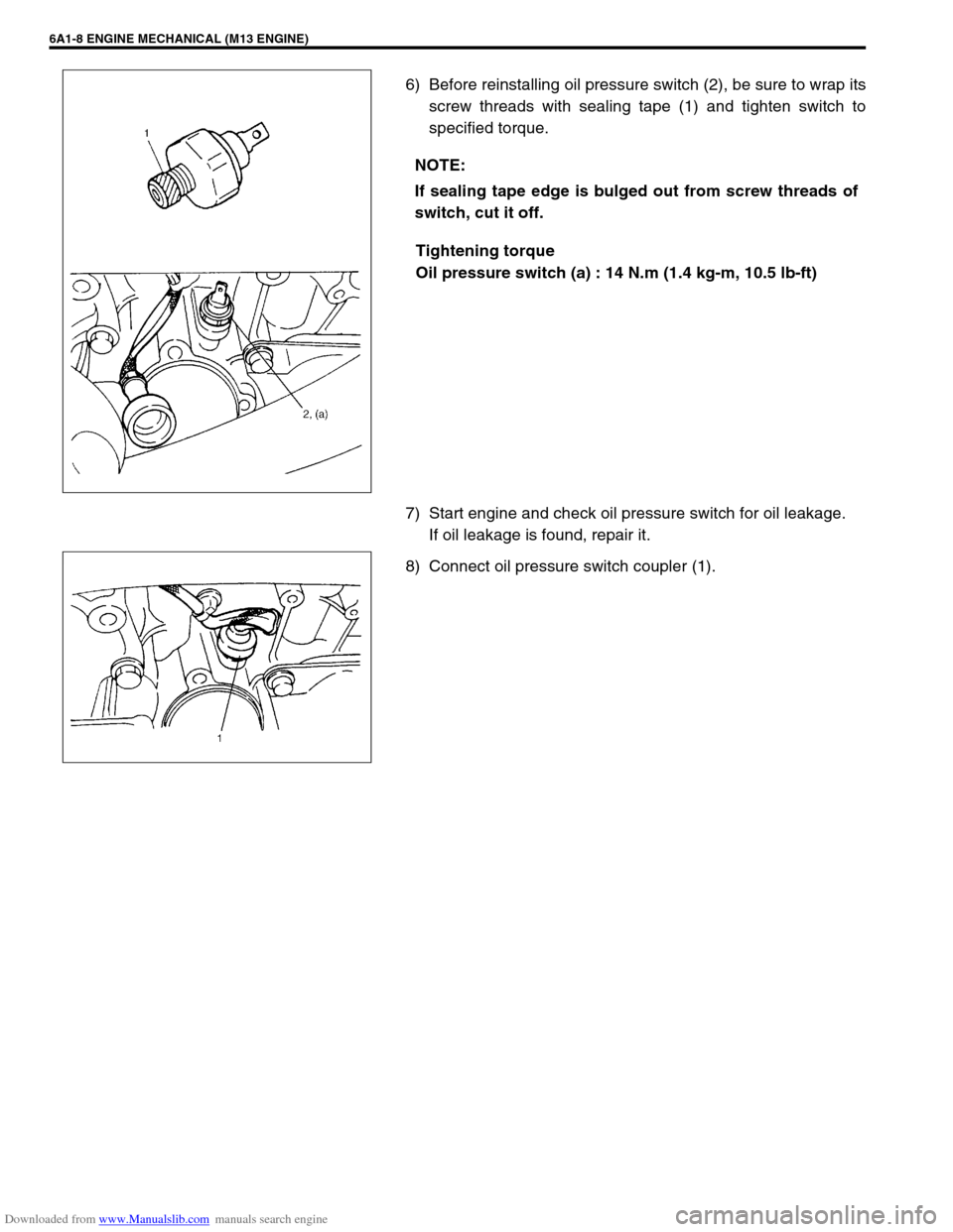
6) Before reinstalling oil pressure switch (2), be sure to wrap its
screw threads with sealing tape (1) and tighten switch to
specified torque.
Tightening torque
Oil pressure switch (a) : 14 N.m (1.4 kg-m, 10.5 lb-ft)
7) Start engine and check oil pressure switch for oil leakage.
If oil leakage is found, repair it.
8) Connect oil pressure switch coupler (1).NOTE:
If sealing tape edge is bulged out from screw threads of
switch, cut it off.
Page 491 of 687
Downloaded from www.Manualslib.com manuals search engine 6A1-10 ENGINE MECHANICAL (M13 ENGINE)
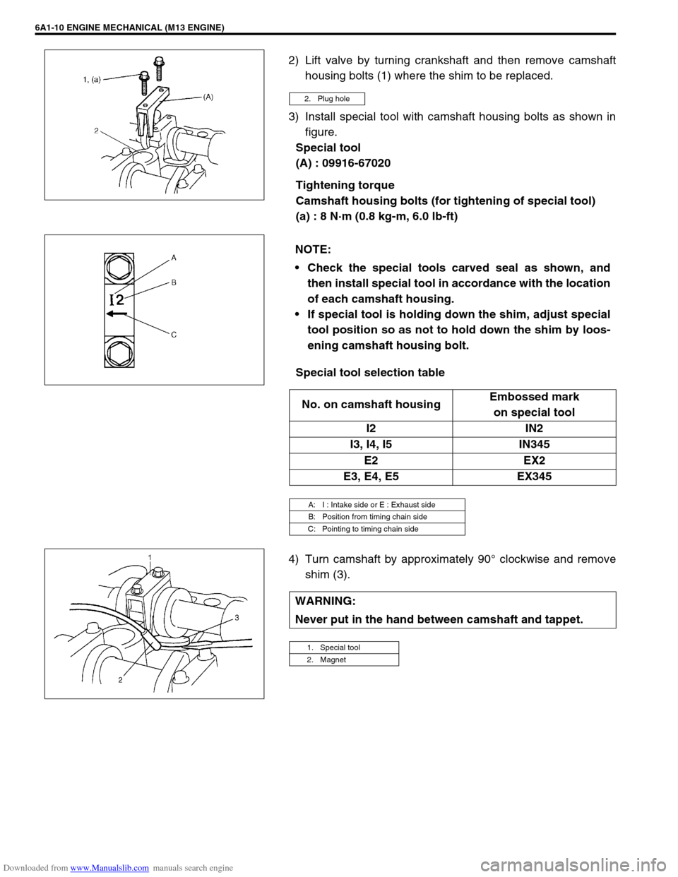
2) Lift valve by turning crankshaft and then remove camshaft
housing bolts (1) where the shim to be replaced.
3) Install special tool with camshaft housing bolts as shown in
figure.
Special tool
(A) : 09916-67020
Tightening torque
Camshaft housing bolts (for tightening of special tool)
(a) : 8 N·m (0.8 kg-m, 6.0 lb-ft)
Special tool selection table
4) Turn camshaft by approximately 90° clockwise and remove
shim (3).
2. Plug hole
NOTE:
Check the special tools carved seal as shown, and
then install special tool in accordance with the location
of each camshaft housing.
If special tool is holding down the shim, adjust special
tool position so as not to hold down the shim by loos-
ening camshaft housing bolt.
No. on camshaft housingEmbossed mark
on special tool
I2 IN2
I3, I4, I5 IN345
E2 EX2
E3, E4, E5 EX345
A: I : Intake side or E : Exhaust side
B: Position from timing chain side
C: Pointing to timing chain side
WARNING:
Never put in the hand between camshaft and tappet.
1. Special tool
2. Magnet
Page 493 of 687
Downloaded from www.Manualslib.com manuals search engine 6A1-12 ENGINE MECHANICAL (M13 ENGINE)
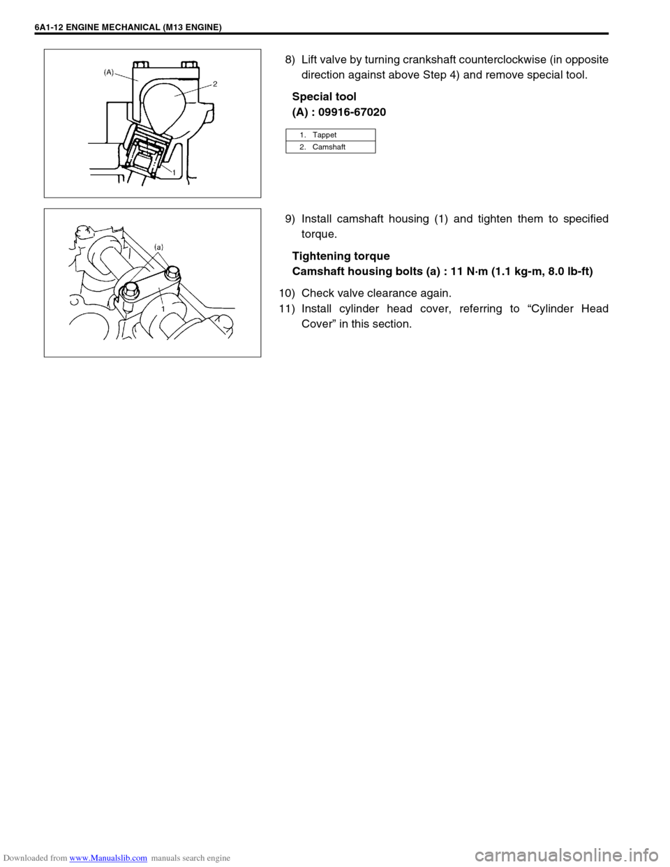
8) Lift valve by turning crankshaft counterclockwise (in opposite
direction against above Step 4) and remove special tool.
Special tool
(A) : 09916-67020
9) Install camshaft housing (1) and tighten them to specified
torque.
Tightening torque
Camshaft housing bolts (a) : 11 N·m (1.1 kg-m, 8.0 lb-ft)
10) Check valve clearance again.
11) Install cylinder head cover, referring to “Cylinder Head
Cover” in this section.
1. Tappet
2. Camshaft
Page 495 of 687
Downloaded from www.Manualslib.com manuals search engine 6A1-14 ENGINE MECHANICAL (M13 ENGINE)
Air Cleaner Assembly
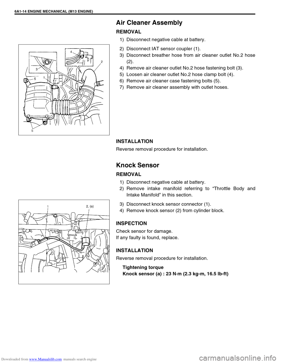
REMOVAL
1) Disconnect negative cable at battery.
2) Disconnect IAT sensor coupler (1).
3) Disconnect breather hose from air cleaner outlet No.2 hose
(2).
4) Remove air cleaner outlet No.2 hose fastening bolt (3).
5) Loosen air cleaner outlet No.2 hose clamp bolt (4).
6) Remove air cleaner case fastening bolts (5).
7) Remove air cleaner assembly with outlet hoses.
INSTALLATION
Reverse removal procedure for installation.
Knock Sensor
REMOVAL
1) Disconnect negative cable at battery.
2) Remove intake manifold referring to “Throttle Body and
Intake Manifold” in this section.
3) Disconnect knock sensor connector (1).
4) Remove knock sensor (2) from cylinder block.
INSPECTION
Check sensor for damage.
If any faulty is found, replace.
INSTALLATION
Reverse removal procedure for installation.
Tightening torque
Knock sensor (a) : 23 N·m (2.3 kg-m, 16.5 lb-ft)
Page 498 of 687
Downloaded from www.Manualslib.com manuals search engine ENGINE MECHANICAL (M13 ENGINE) 6A1-17
3) Install cylinder head cover to cylinder head.
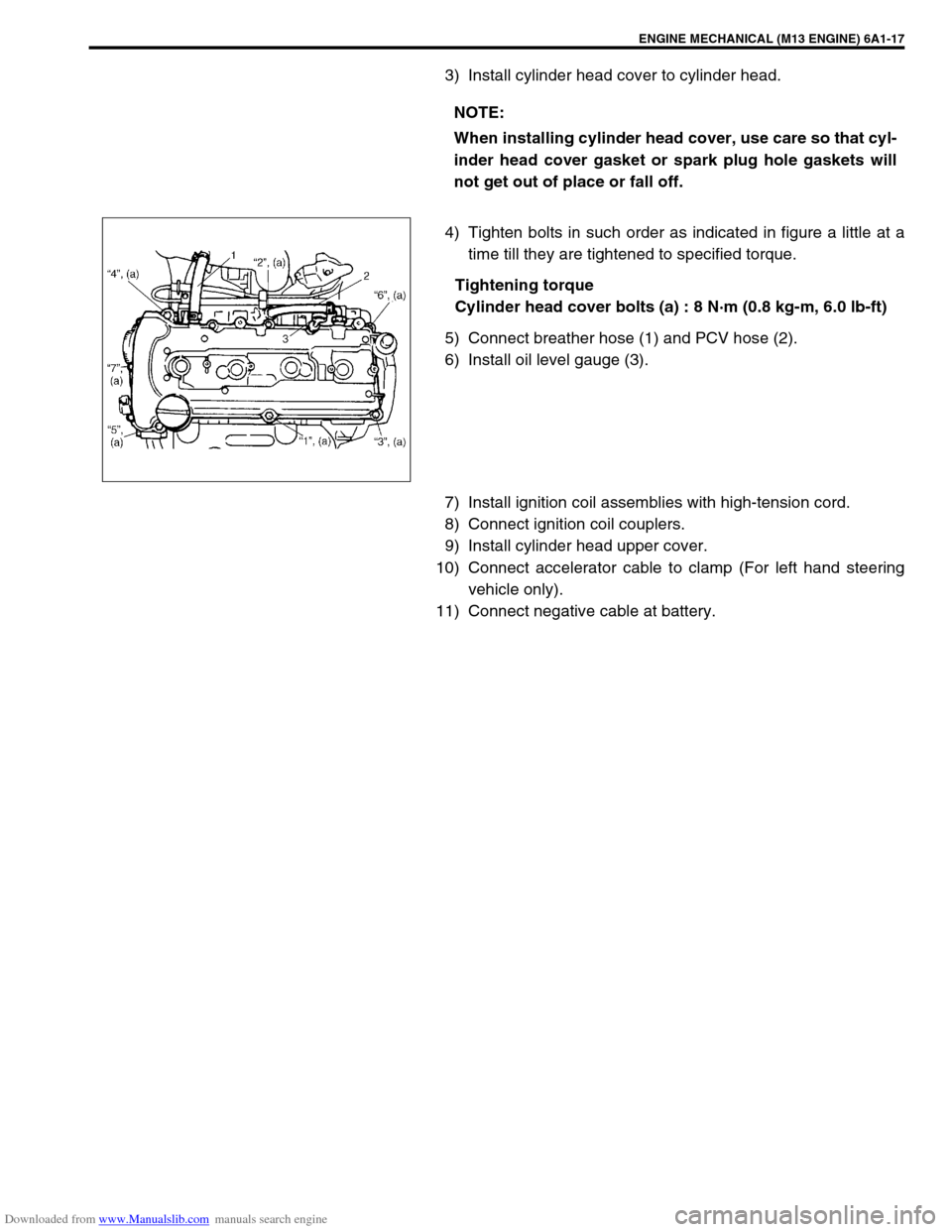
4) Tighten bolts in such order as indicated in figure a little at a
time till they are tightened to specified torque.
Tightening torque
Cylinder head cover bolts (a) : 8 N·m (0.8 kg-m, 6.0 lb-ft)
5) Connect breather hose (1) and PCV hose (2).
6) Install oil level gauge (3).
7) Install ignition coil assemblies with high-tension cord.
8) Connect ignition coil couplers.
9) Install cylinder head upper cover.
10) Connect accelerator cable to clamp (For left hand steering
vehicle only).
11) Connect negative cable at battery.NOTE:
When installing cylinder head cover, use care so that cyl-
inder head cover gasket or spark plug hole gaskets will
not get out of place or fall off.