torque SUZUKI JIMNY 2005 3.G Service Manual Online
[x] Cancel search | Manufacturer: SUZUKI, Model Year: 2005, Model line: JIMNY, Model: SUZUKI JIMNY 2005 3.GPages: 687, PDF Size: 13.38 MB
Page 255 of 687
Downloaded from www.Manualslib.com manuals search engine 4B-2 PROPELLER SHAFTS
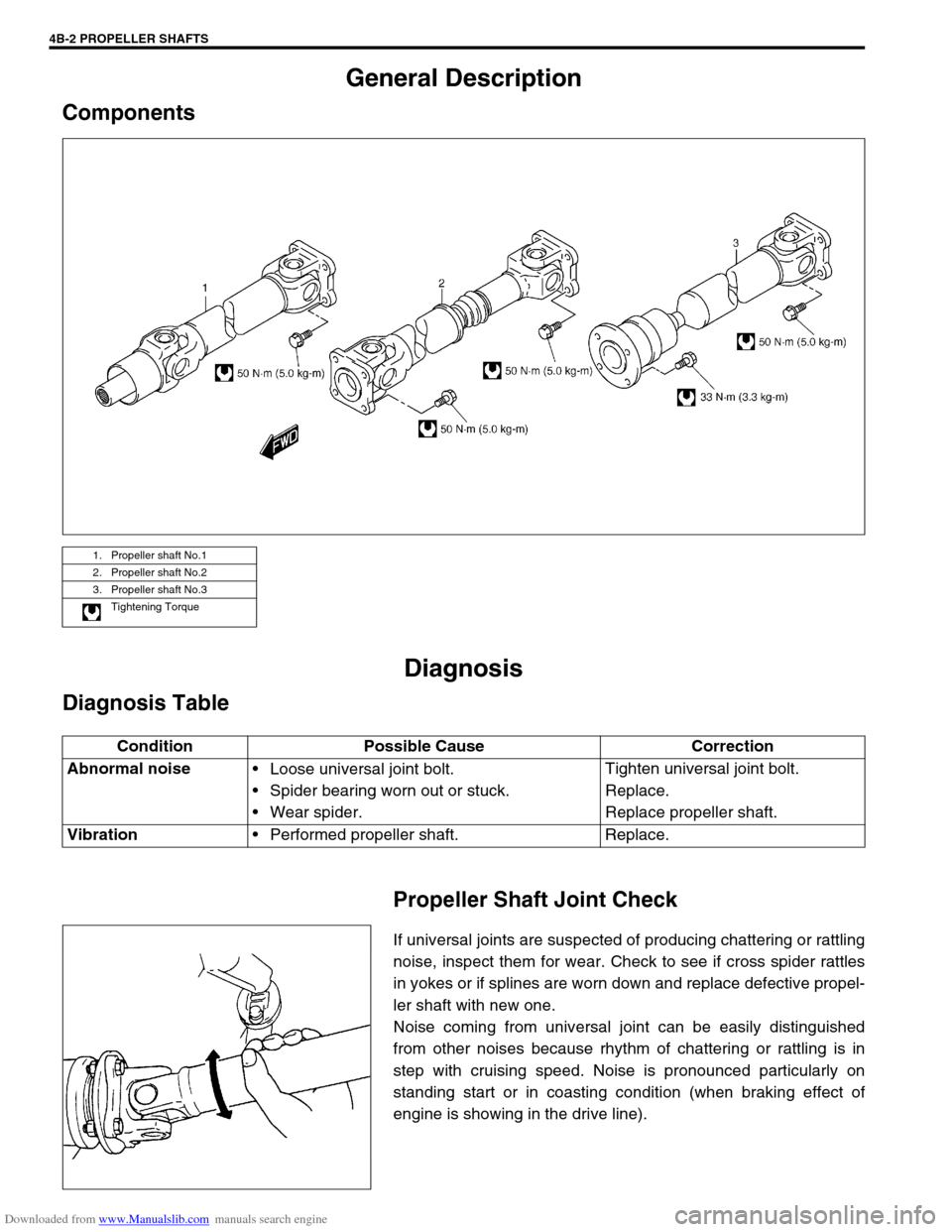
General Description
Components
Diagnosis
Diagnosis Table
Propeller Shaft Joint Check
If universal joints are suspected of producing chattering or rattling
noise, inspect them for wear. Check to see if cross spider rattles
in yokes or if splines are worn down and replace defective propel-
ler shaft with new one.
Noise coming from universal joint can be easily distinguished
from other noises because rhythm of chattering or rattling is in
step with cruising speed. Noise is pronounced particularly on
standing start or in coasting condition (when braking effect of
engine is showing in the drive line).
1. Propeller shaft No.1
2. Propeller shaft No.2
3. Propeller shaft No.3
Tightening Torque
Condition Possible Cause Correction
Abnormal noise
Loose universal joint bolt.
Spider bearing worn out or stuck.
Wear spider.Tighten universal joint bolt.
Replace.
Replace propeller shaft.
Vibration
Performed propeller shaft. Replace.
Page 257 of 687
Downloaded from www.Manualslib.com manuals search engine 4B-4 PROPELLER SHAFTS
INSTALLATION
Install propeller shaft(s) reversing removal procedure noting fol-
lowing points :
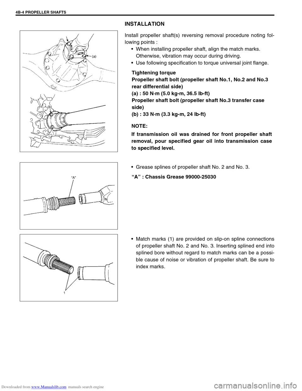
When installing propeller shaft, align the match marks.
Otherwise, vibration may occur during driving.
Use following specification to torque universal joint flange.
Tightening torque
Propeller shaft bolt (propeller shaft No.1, No.2 and No.3
rear differential side)
(a) : 50 N·m (5.0 kg-m, 36.5 lb-ft)
Propeller shaft bolt (propeller shaft No.3 transfer case
side)
(b) : 33 N·m (3.3 kg-m, 24 lb-ft)
Grease splines of propeller shaft No. 2 and No. 3.
“A” : Chassis Grease 99000-25030
Match marks (1) are provided on slip-on spline connections
of propeller shaft No. 2 and No. 3. Inserting splined end into
spIined bore without regard to match marks can be a possi-
ble cause of noise or vibration of propeller shaft. Be sure to
index marks. NOTE:
If transmission oil was drained for front propeller shaft
removal, pour specified gear oil into transmission case
to specified level.
Page 260 of 687
Downloaded from www.Manualslib.com manuals search engine PROPELLER SHAFTS 4B-7
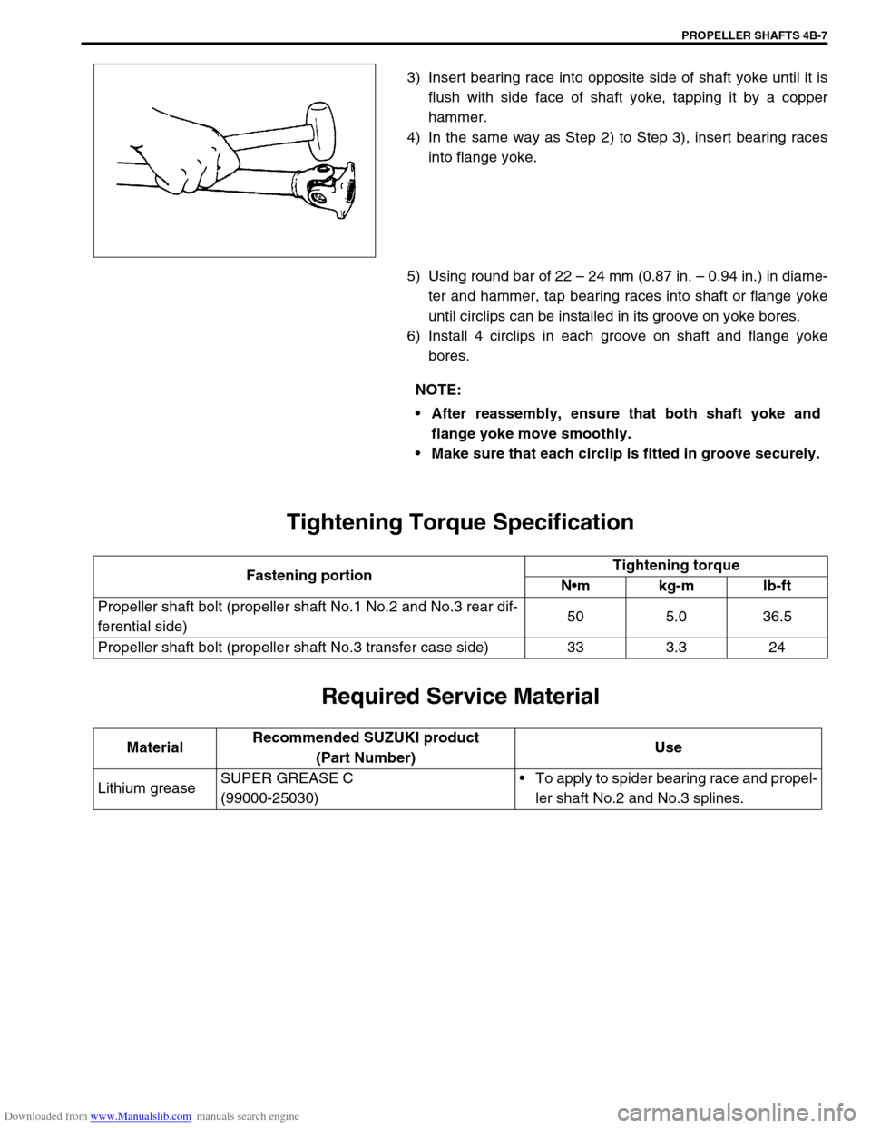
3) Insert bearing race into opposite side of shaft yoke until it is
flush with side face of shaft yoke, tapping it by a copper
hammer.
4) In the same way as Step 2) to Step 3), insert bearing races
into flange yoke.
5) Using round bar of 22 – 24 mm (0.87 in. – 0.94 in.) in diame-
ter and hammer, tap bearing races into shaft or flange yoke
until circlips can be installed in its groove on yoke bores.
6) Install 4 circlips in each groove on shaft and flange yoke
bores.
Tightening Torque Specification
Required Service Material
NOTE:
After reassembly, ensure that both shaft yoke and
flange yoke move smoothly.
Make sure that each circlip is fitted in groove securely.
Fastening portionTightening torque
Nm kg-m lb-ft
Propeller shaft bolt (propeller shaft No.1 No.2 and No.3 rear dif-
ferential side)50 5.0 36.5
Propeller shaft bolt (propeller shaft No.3 transfer case side) 33 3.3 24
MaterialRecommended SUZUKI product
(Part Number)Use
Lithium greaseSUPER GREASE C
(99000-25030)To apply to spider bearing race and propel-
ler shaft No.2 and No.3 splines.
Page 262 of 687
Downloaded from www.Manualslib.com manuals search engine BRAKES 5-1
6F1
6F2
6G
6H
6K
7A
7A1
7B1
7C1
7D
7E
5
9
10
10A
10B
9
10
10A
10B
SECTION 5
BRAKES
CONTENTS
General Description ......................................... 5-3
Diagnosis .......................................................... 5-4
Road Testing Brakes ...................................... 5-4
Brake Fluid Leaks .......................................... 5-4
Substandard or Contaminated Brake Fluid .... 5-4
Diagnosis Table ............................................. 5-5
Brake Pedal Free Height Adjustment ............. 5-8
Brake Pedal Play Check ................................ 5-8
Stop Light Switch Adjustment ........................ 5-8
Excessive Pedal Travel Check ....................... 5-9
Front Brake Disc Check ................................. 5-9
Front Brake Pad Check .................................. 5-9
Rear Brake Shoe Check .............................. 5-10
Master Cylinder and Brake Fluid Level
Check ........................................................... 5-10
Rear Drum Brake Shoe Adjustment ............. 5-11
Parking Brake Inspection and Adjustment ... 5-11
Booster Operation Check ............................. 5-12Fluid Pressure Test
(If Equipped with LSPV) ............................... 5-15
On-Vehicle Service ........................................ 5-17
Air Bleeding of Brake System ...................... 5-17
Brake Hose and Pipe Inspection.................. 5-18
Front Disc Brake .......................................... 5-19
Brake pad ................................................. 5-20
Caliper assembly...................................... 5-22
Brake Disc.................................................... 5-26
Rear Brake ................................................... 5-29
Brake drum............................................... 5-29
Brake shoe ............................................... 5-32
Wheel Cylinder............................................. 5-33
Brake back plate ...................................... 5-34
Master Cylinder .............................................. 5-36
Master Cylinder Reservoir ........................... 5-36
Master Cylinder Assembly ........................... 5-37 WARNING:
For lifting point of vehicle, refer to Section 0A.
WARNING:
For vehicles equipped with Supplement Restraint (Air Bag) System:
Service on and around the air bag system components or wiring must be performed only by an
authorized SUZUKI dealer. Refer to “Air Bag System Components and Wiring Location View” under
“General Description” in air bag system section in order to confirm whether you are performing ser-
vice on or near the air bag system components or wiring. Please observe all WARNINGS and “Ser-
vice Precautions” under “On-Vehicle Service” in air bag system section before performing service
on or around the air bag system components or wiring. Failure to follow WARNINGS could result in
unintentional activation of the system or could render the system inoperative. Either of these two
conditions may result in severe injury.
Technical service work must be started at least 90 seconds after the ignition switch is turned to the
“LOCK” position and the negative cable is disconnected from the battery. Otherwise, the system
may be activated by reserve energy in the Sensing and Diagnostic Module (SDM).
NOTE:
When inspecting and servicing vehicle equipped with ABS, be sure to refer to section 5E first.
All brake fasteners are important attaching parts in that they could affect the performance of vital
parts and systems, and/or could result in major repair expense. They must be replaced with one of
same part number or with an equivalent part if replacement becomes necessary. Do not use a
replacement part of lesser quality or substitute design. Torque values must be used as specified
during reassembly to assure proper retention of all parts. There is to be no welding as it may result
in extensive damage and weakening of the metal.
Page 263 of 687

Downloaded from www.Manualslib.com manuals search engine 5-2 BRAKES
Master Cylinder ............................................ 5-38
Fill Reservoir ................................................ 5-40
LSPV (Load Sensing Proportioning Valve)
Assembly (If Equipped) ................................. 5-42
LSPV Assembly ........................................... 5-43
P (Proportioning) Valve ................................. 5-44
Brake Booster ................................................ 5-45
Inspection and adjustment ....................... 5-46
Brake Hose/Pipe .......................................... 5-48Front brake hose/pipe ............................... 5-48
Rear Brake Hose/Pipe .................................. 5-51
Parking Brake Lever/Cable ........................... 5-52
Parking brake lever ................................... 5-52
Parking Brake Cable ..................................... 5-53
Tightening Torque Specifications ................. 5-54
Required Service Material.............................. 5-54
Special Tool .................................................... 5-55
Page 264 of 687
Downloaded from www.Manualslib.com manuals search engine BRAKES 5-3
General Description
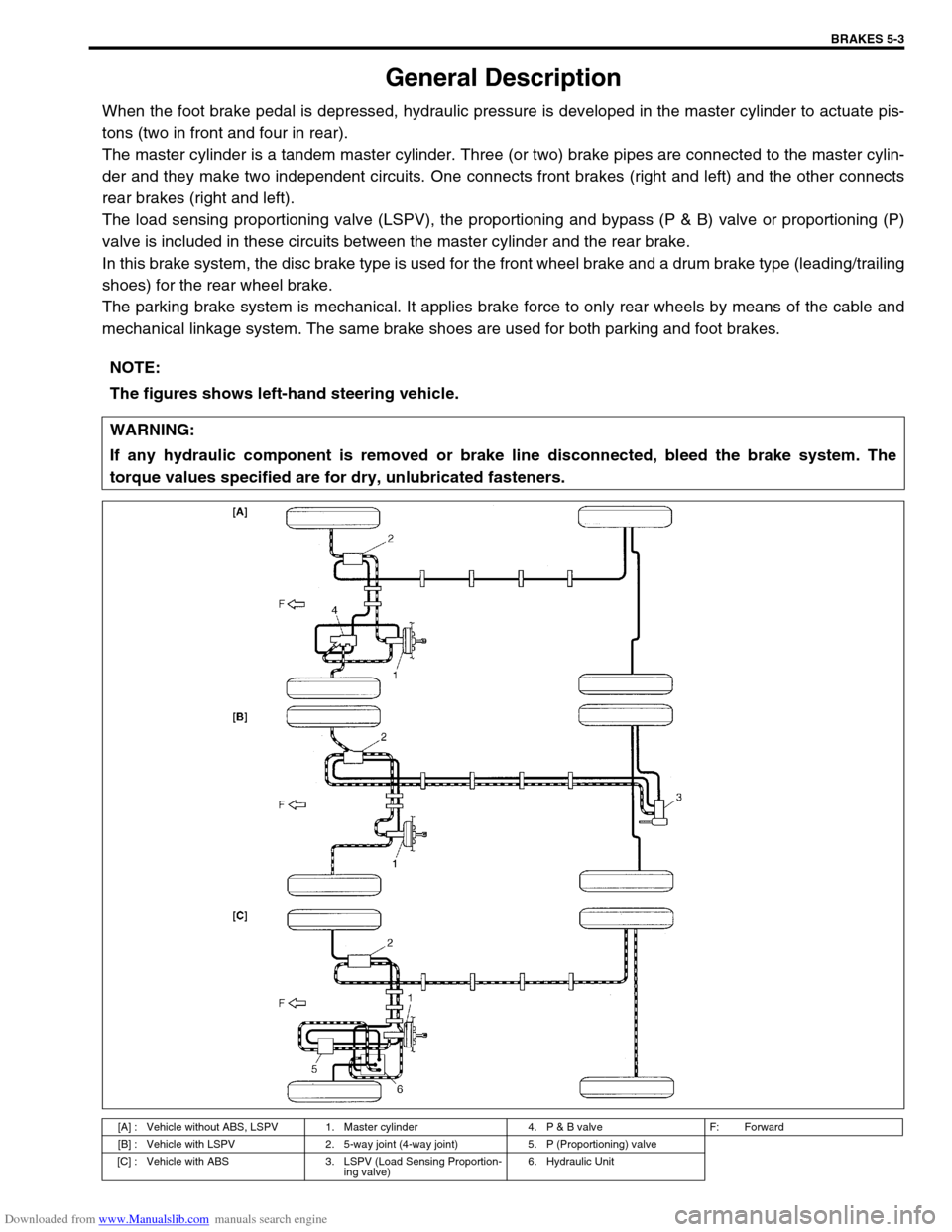
When the foot brake pedal is depressed, hydraulic pressure is developed in the master cylinder to actuate pis-
tons (two in front and four in rear).
The master cylinder is a tandem master cylinder. Three (or two) brake pipes are connected to the master cylin-
der and they make two independent circuits. One connects front brakes (right and left) and the other connects
rear brakes (right and left).
The load sensing proportioning valve (LSPV), the proportioning and bypass (P & B) valve or proportioning (P)
valve is included in these circuits between the master cylinder and the rear brake.
In this brake system, the disc brake type is used for the front wheel brake and a drum brake type (leading/trailing
shoes) for the rear wheel brake.
The parking brake system is mechanical. It applies brake force to only rear wheels by means of the cable and
mechanical linkage system. The same brake shoes are used for both parking and foot brakes.
NOTE:
The figures shows left-hand steering vehicle.
WARNING:
If any hydraulic component is removed or brake line disconnected, bleed the brake system. The
torque values specified are for dry, unlubricated fasteners.
[A] : Vehicle without ABS, LSPV 1. Master cylinder 4. P & B valve F: Forward
[B] : Vehicle with LSPV 2. 5-way joint (4-way joint) 5. P (Proportioning) valve
[C] : Vehicle with ABS 3. LSPV (Load Sensing Proportion-
ing valve)6. Hydraulic Unit
Page 266 of 687

Downloaded from www.Manualslib.com manuals search engine BRAKES 5-5
Diagnosis Table
Condition Possible Cause Correction
Not enough braking
forceBrake oil leakage from brake lines Locate leaking point and repair.
Brake disc or pads stained with oil Clean or replace.
Overheated brakes Determine cause and repair.
Poor contact of shoes on brake drum Repair for proper contact.
Brake shoes linings stained with oil or wet with
waterReplace.
Badly worn brake shoe linings Replace.
Defective wheel cylinders Repair or replace.
Malfunctioning caliper assembly Repair or replace.
Air in system Bleed system.
Maladjusted sensor spring length of LSPV Check or adjust.
Broken sensor spring of LSPV Replace.
Defective collar of LSPV Replace.
Malfunctioning ABS (Antilock brake system), if
equippedCheck system and replace as nec-
essary.
Brake pull (Brakes not
working in unison)Pad or shoe linings are wet with water or
stained with oil in some brakesReplace.
Drum-to-shoe clearance out of adjustment in
some brakes (Malfunctioning auto adjusting
mechanism)Check for inoperative auto adjusting
mechanism.
Drum is out of round in some brakes Replace.
Wheel tires are inflated unequally Inflate equally.
Malfunctioning wheel cylinders Repair or replace.
Disturbed front wheel alignment Adjust as prescribed.
Unmatched tires on same axle Tires with approximately the same
amount of tread should be used on
the same axle.
Restricted brake tubes or hoses Check for soft hoses and damaged
lines.
Replace with new hoses and new
double-walled steel brake tubing.
Malfunctioning caliper assembly Check for stuck or sluggish pistons
and proper lubrication of caliper
slide bush.
Loose suspension parts Caliper should slide.
Check all suspension mountings.
Loose calipers Check and torque bolts to specifica-
tions.
Noise (high pitched
squeak without brake
applied)Front lining worn out Replace brake pads.
Rear brake locked pre-
maturelyMaladjusted sensor spring length of LSPV Check or adjust.
Malfunctioning LSPV assembly Replace assembly.
Brake locked
(For vehicles
equipped with ABS)Malfunctioning ABS, if equipped Check system and replace as nec-
essary.
Page 269 of 687
Downloaded from www.Manualslib.com manuals search engine 5-8 BRAKES
Brake Pedal Free Height Adjustment
1) Check brake pedal free height.
If it is not within specification, check and adjust following item
2) and 3).
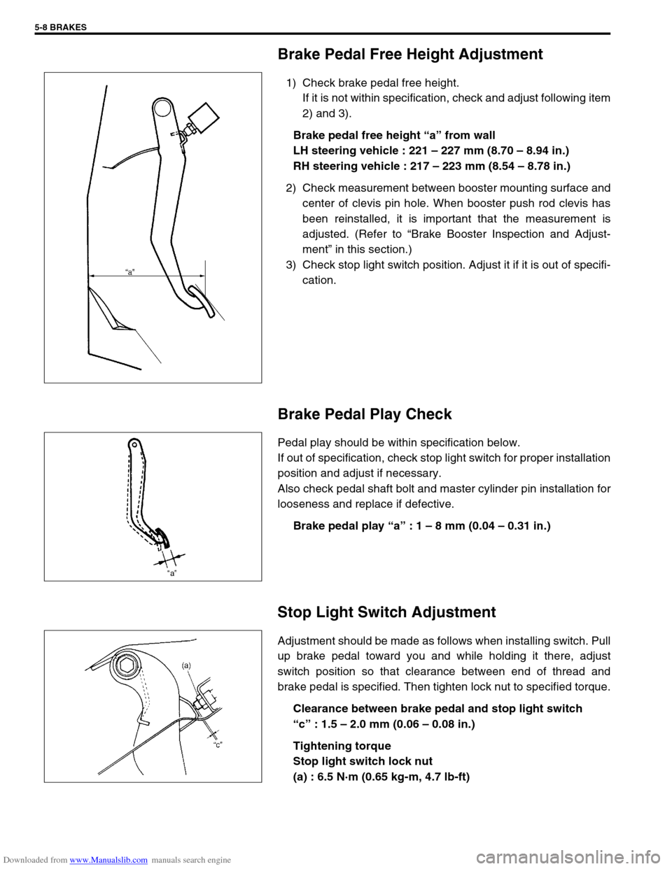
Brake pedal free height “a” from wall
LH steering vehicle : 221 – 227 mm (8.70 – 8.94 in.)
RH steering vehicle : 217 – 223 mm (8.54 – 8.78 in.)
2) Check measurement between booster mounting surface and
center of clevis pin hole. When booster push rod clevis has
been reinstalled, it is important that the measurement is
adjusted. (Refer to “Brake Booster Inspection and Adjust-
ment” in this section.)
3) Check stop light switch position. Adjust it if it is out of specifi-
cation.
Brake Pedal Play Check
Pedal play should be within specification below.
If out of specification, check stop light switch for proper installation
position and adjust if necessary.
Also check pedal shaft bolt and master cylinder pin installation for
looseness and replace if defective.
Brake pedal play “a” : 1 – 8 mm (0.04 – 0.31 in.)
Stop Light Switch Adjustment
Adjustment should be made as follows when installing switch. Pull
up brake pedal toward you and while holding it there, adjust
switch position so that clearance between end of thread and
brake pedal is specified. Then tighten lock nut to specified torque.
Clearance between brake pedal and stop light switch
“c” : 1.5 – 2.0 mm (0.06 – 0.08 in.)
Tightening torque
Stop light switch lock nut
(a) : 6.5 N·m (0.65 kg-m, 4.7 lb-ft)
Page 277 of 687

Downloaded from www.Manualslib.com manuals search engine 5-16 BRAKES
4) If rear brake pressure is not within specification, adjust it by
changing stay position as follows.
If rear brake pressure is higher than specification, move stay
“A” to direction “l” and if it is lower, to direction “r”.
Repeat steps 3) and 4) until rear brake pressure is within
specification.
After adjustment, be sure to torque bolt to specification.
Tightening torque
LSPV adjust bolt
(a) : 25 N·m (2.5 kg-m, 18 Ib-ft)
5) Disconnect brake pipe (2) (connecting between master cylin-
der secondary side and 4-way joint) from master cylinder (1).
Tighten plug (special tool) to master cylinder.
Depress brake pedal. If rear brake pressure is 95 – 100
kg/cm
2 when front brake pressure is 100 kg/cm2, it means
that front fail-safe system functions properly.
Special tool
(A) : 09956-02210
1. LSPV lever
2. LSPV spring
3. LSPV stay
Front brake Rear brake
10000 kPa
100 kg/cm
2
1422 psi9500 – 10000 kPa
95 – 100 kg/cm
2
1350 – 1422 psi
Page 279 of 687
Downloaded from www.Manualslib.com manuals search engine 5-18 BRAKES
4) When fluid pressure in the cylinder is almost depleted,
retighten bleeder plug.
5) Repeat this operation until there are no more air bubbles in
hydraulic line.
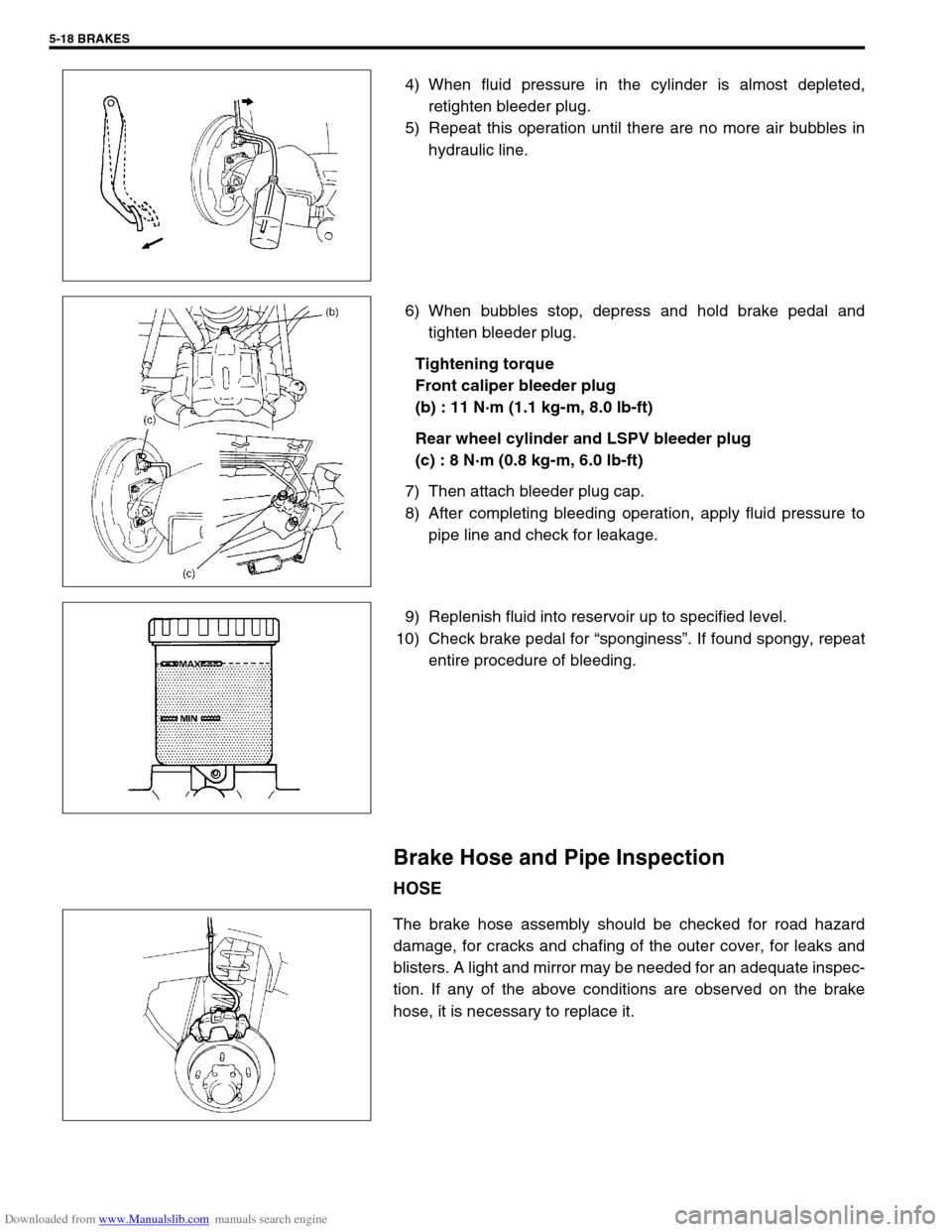
6) When bubbles stop, depress and hold brake pedal and
tighten bleeder plug.
Tightening torque
Front caliper bleeder plug
(b) : 11 N·m (1.1 kg-m, 8.0 lb-ft)
Rear wheel cylinder and LSPV bleeder plug
(c) : 8 N·m (0.8 kg-m, 6.0 lb-ft)
7) Then attach bleeder plug cap.
8) After completing bleeding operation, apply fluid pressure to
pipe line and check for leakage.
9) Replenish fluid into reservoir up to specified level.
10) Check brake pedal for “sponginess”. If found spongy, repeat
entire procedure of bleeding.
Brake Hose and Pipe Inspection
HOSE
The brake hose assembly should be checked for road hazard
damage, for cracks and chafing of the outer cover, for leaks and
blisters. A light and mirror may be needed for an adequate inspec-
tion. If any of the above conditions are observed on the brake
hose, it is necessary to replace it.