bolts SUZUKI JIMNY 2005 3.G Service Workshop Manual
[x] Cancel search | Manufacturer: SUZUKI, Model Year: 2005, Model line: JIMNY, Model: SUZUKI JIMNY 2005 3.GPages: 687, PDF Size: 13.38 MB
Page 600 of 687
Downloaded from www.Manualslib.com manuals search engine ENGINE FUEL 6C-5
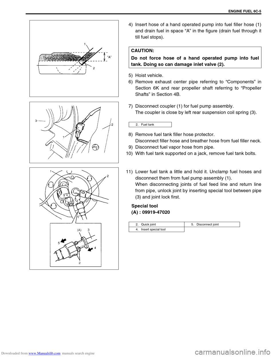
4) Insert hose of a hand operated pump into fuel filler hose (1)
and drain fuel in space “A” in the figure (drain fuel through it
till fuel stops).
5) Hoist vehicle.
6) Remove exhaust center pipe referring to “Components” in
Section 6K and rear propeller shaft referring to “Propeller
Shafts” in Section 4B.
7) Disconnect coupler (1) for fuel pump assembly.
The coupler is close by left rear suspension coil spring (3).
8) Remove fuel tank filler hose protector.
Disconnect filler hose and breather hose from fuel filler neck.
9) Disconnect fuel vapor hose from pipe.
10) With fuel tank supported on a jack, remove fuel tank bolts.
11) Lower fuel tank a little and hold it. Unclamp fuel hoses and
disconnect them from fuel pump assembly (1).
When disconnecting joints of fuel feed line and return line
from pipe, unlock joint by inserting special tool between pipe
(3) and joint lock first.
Special tool
(A) : 09919-47020 CAUTION:
Do not force hose of a hand operated pump into fuel
tank. Doing so can damage inlet valve (2).
2. Fuel tank
2. Quick joint 5. Disconnect joint
4. Insert special tool
Page 602 of 687
Downloaded from www.Manualslib.com manuals search engine ENGINE FUEL 6C-7
INSTALLATION
1) Install fuel pump (1) assembly to fuel tank. Refer to “Fuel
Pump Assembly” in this section. Install protector to fuel tank.
2) Install inlet valve to fuel tank.
If deformed or damaged in any other way, replace with a new
one.
3) Connect fuel filler and breather hoses to fuel tank and vapor
hose to fuel pump assembly. Clamp them securely.
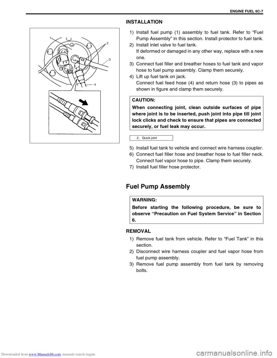
4) Lift up fuel tank on jack.
Connect fuel feed hose (4) and return hose (3) to pipes as
shown in figure and clamp them securely.
5) Install fuel tank to vehicle and connect wire harness coupler.
6) Connect fuel filler hose and breather hose to fuel filler neck.
Connect fuel vapor hose to pipe. Clamp them securely.
7) Install fuel filler hose protector.
Fuel Pump Assembly
REMOVAL
1) Remove fuel tank from vehicle. Refer to “Fuel Tank” in this
section.
2) Disconnect wire harness coupler and fuel vapor hose from
fuel pump assembly.
3) Remove fuel pump assembly from fuel tank by removing
bolts. CAUTION:
When connecting joint, clean outside surfaces of pipe
where joint is to be inserted, push joint into pipe till joint
lock clicks and check to ensure that pipes are connected
securely, or fuel leak may occur.
2. Quick joint
WARNING:
Before starting the following procedure, be sure to
observe “Precaution on Fuel System Service” in Section
6.
Page 604 of 687
Downloaded from www.Manualslib.com manuals search engine ENGINE FUEL 6C-9
INSTALLATION
1) Clean mating surfaces of fuel pump assembly and fuel tank.
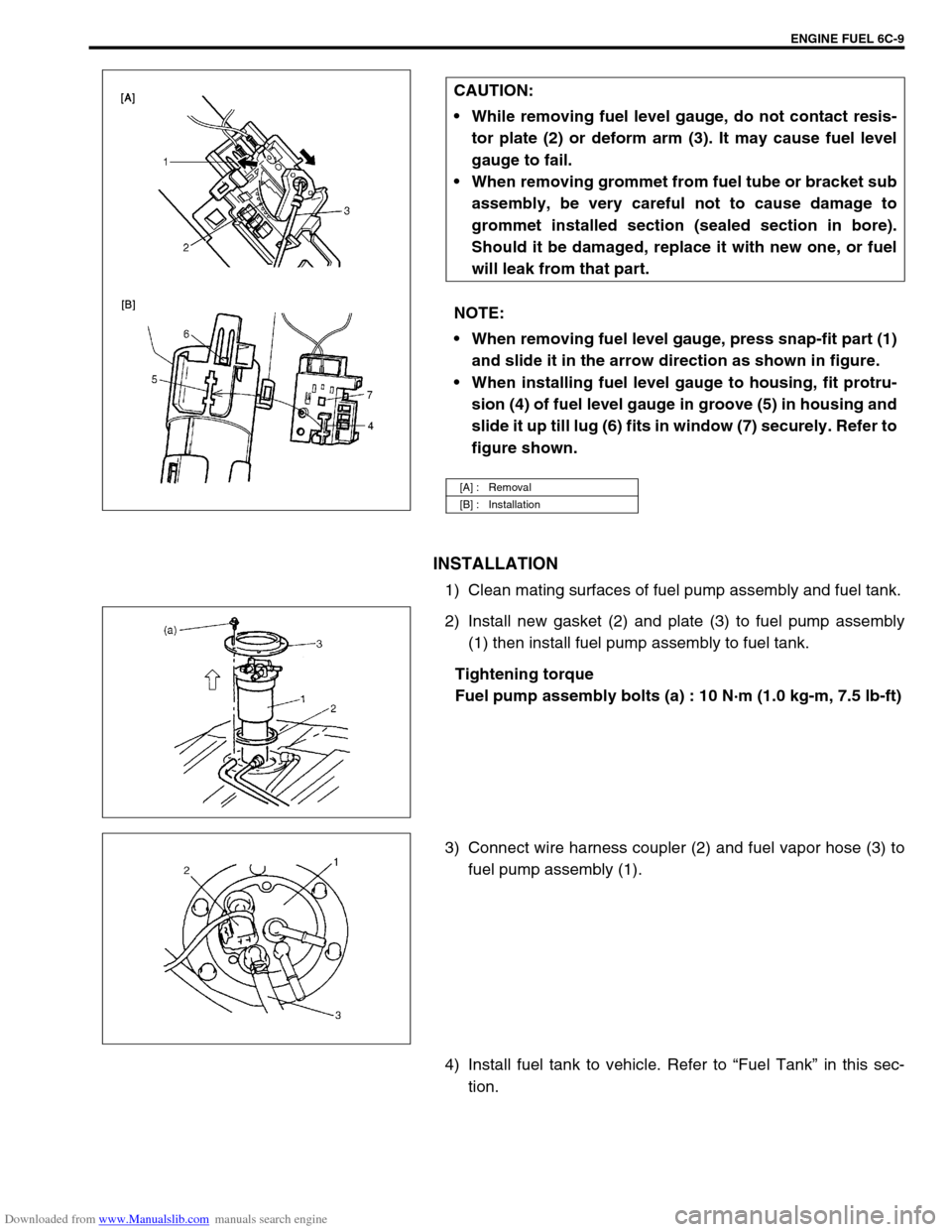
2) Install new gasket (2) and plate (3) to fuel pump assembly
(1) then install fuel pump assembly to fuel tank.
Tightening torque
Fuel pump assembly bolts (a) : 10 N·m (1.0 kg-m, 7.5 lb-ft)
3) Connect wire harness coupler (2) and fuel vapor hose (3) to
fuel pump assembly (1).
4) Install fuel tank to vehicle. Refer to “Fuel Tank” in this sec-
tion. CAUTION:
While removing fuel level gauge, do not contact resis-
tor plate (2) or deform arm (3). It may cause fuel level
gauge to fail.
When removing grommet from fuel tube or bracket sub
assembly, be very careful not to cause damage to
grommet installed section (sealed section in bore).
Should it be damaged, replace it with new one, or fuel
will leak from that part.
NOTE:
When removing fuel level gauge, press snap-fit part (1)
and slide it in the arrow direction as shown in figure.
When installing fuel level gauge to housing, fit protru-
sion (4) of fuel level gauge in groove (5) in housing and
slide it up till lug (6) fits in window (7) securely. Refer to
figure shown.
[A] : Removal
[B] : Installation
Page 630 of 687
Downloaded from www.Manualslib.com manuals search engine ENGINE AND EMISSION CONTROL SYSTEM 6E-25
INSTALLATION
For installation, reverse removal procedure and note following
precautions.
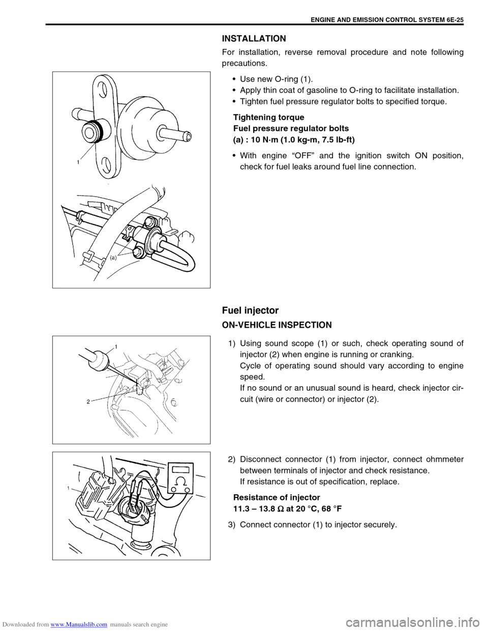
Use new O-ring (1).
Apply thin coat of gasoline to O-ring to facilitate installation.
Tighten fuel pressure regulator bolts to specified torque.
Tightening torque
Fuel pressure regulator bolts
(a) : 10 N·m (1.0 kg-m, 7.5 lb-ft)
With engine “OFF” and the ignition switch ON position,
check for fuel leaks around fuel line connection.
Fuel injector
ON-VEHICLE INSPECTION
1) Using sound scope (1) or such, check operating sound of
injector (2) when engine is running or cranking.
Cycle of operating sound should vary according to engine
speed.
If no sound or an unusual sound is heard, check injector cir-
cuit (wire or connector) or injector (2).
2) Disconnect connector (1) from injector, connect ohmmeter
between terminals of injector and check resistance.
If resistance is out of specification, replace.
Resistance of injector
11.3 – 13.8
Ω
ΩΩ Ω at 20 °C, 68 °F
3) Connect connector (1) to injector securely.
Page 631 of 687
Downloaded from www.Manualslib.com manuals search engine 6E-26 ENGINE AND EMISSION CONTROL SYSTEM
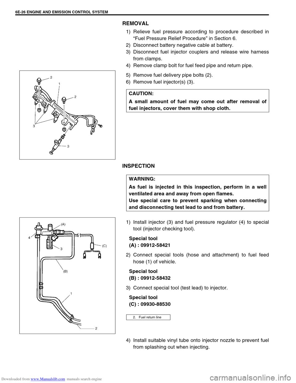
REMOVAL
1) Relieve fuel pressure according to procedure described in
“Fuel Pressure Relief Procedure” in Section 6.
2) Disconnect battery negative cable at battery.
3) Disconnect fuel injector couplers and release wire harness
from clamps.
4) Remove clamp bolt for fuel feed pipe and return pipe.
5) Remove fuel delivery pipe bolts (2).
6) Remove fuel injector(s) (3).
INSPECTION
1) Install injector (3) and fuel pressure regulator (4) to special
tool (injector checking tool).
Special tool
(A) : 09912-58421
2) Connect special tools (hose and attachment) to fuel feed
hose (1) of vehicle.
Special tool
(B) : 09912-58432
3) Connect special tool (test lead) to injector.
Special tool
(C) : 09930-88530
4) Install suitable vinyl tube onto injector nozzle to prevent fuel
from splashing out when injecting. CAUTION:
A small amount of fuel may come out after removal of
fuel injectors, cover them with shop cloth.
WARNING:
As fuel is injected in this inspection, perform in a well
ventilated area and away from open flames.
Use special care to prevent sparking when connecting
and disconnecting test lead to and from battery.
2. Fuel return line
Page 633 of 687
Downloaded from www.Manualslib.com manuals search engine 6E-28 ENGINE AND EMISSION CONTROL SYSTEM
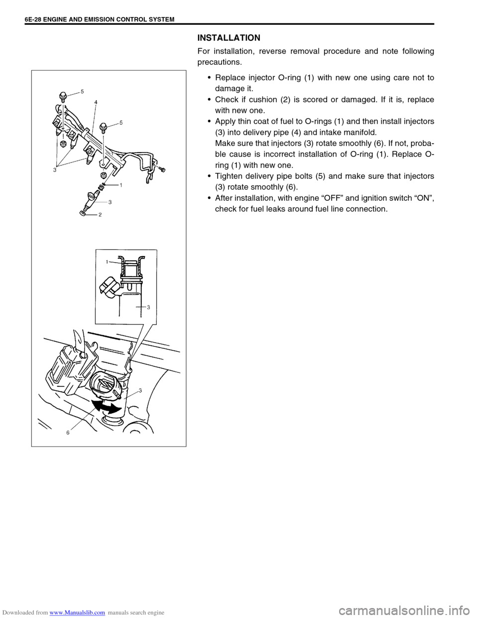
INSTALLATION
For installation, reverse removal procedure and note following
precautions.
Replace injector O-ring (1) with new one using care not to
damage it.
Check if cushion (2) is scored or damaged. If it is, replace
with new one.
Apply thin coat of fuel to O-rings (1) and then install injectors
(3) into delivery pipe (4) and intake manifold.
Make sure that injectors (3) rotate smoothly (6). If not, proba-
ble cause is incorrect installation of O-ring (1). Replace O-
ring (1) with new one.
Tighten delivery pipe bolts (5) and make sure that injectors
(3) rotate smoothly (6).
After installation, with engine “OFF” and ignition switch “ON”,
check for fuel leaks around fuel line connection.
Page 656 of 687
Downloaded from www.Manualslib.com manuals search engine IGNITION SYSTEM (ELECTRONIC IGNITION SYSTEM 6F-7
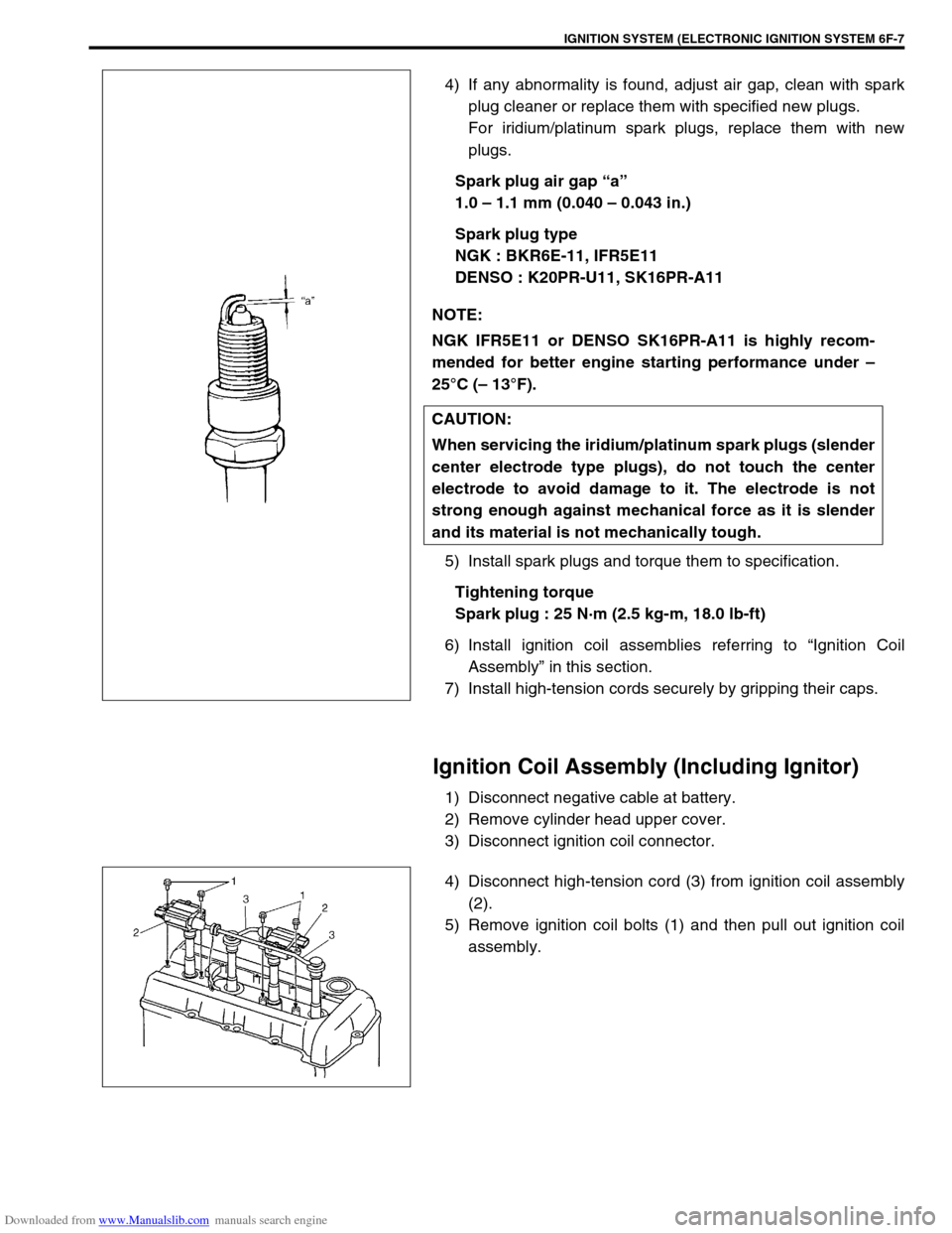
4) If any abnormality is found, adjust air gap, clean with spark
plug cleaner or replace them with specified new plugs.
For iridium/platinum spark plugs, replace them with new
plugs.
Spark plug air gap “a”
1.0 – 1.1 mm (0.040 – 0.043 in.)
Spark plug type
NGK : BKR6E-11, IFR5E11
DENSO : K20PR-U11, SK16PR-A11
5) Install spark plugs and torque them to specification.
Tightening torque
Spark plug : 25 N·m (2.5 kg-m, 18.0 lb-ft)
6) Install ignition coil assemblies referring to “Ignition Coil
Assembly” in this section.
7) Install high-tension cords securely by gripping their caps.
Ignition Coil Assembly (Including Ignitor)
1) Disconnect negative cable at battery.
2) Remove cylinder head upper cover.
3) Disconnect ignition coil connector.
4) Disconnect high-tension cord (3) from ignition coil assembly
(2).
5) Remove ignition coil bolts (1) and then pull out ignition coil
assembly. NOTE:
NGK IFR5E11 or DENSO SK16PR-A11 is highly recom-
mended for better engine starting performance under –
25°C (– 13°F).
CAUTION:
When servicing the iridium/platinum spark plugs (slender
center electrode type plugs), do not touch the center
electrode to avoid damage to it. The electrode is not
strong enough against mechanical force as it is slender
and its material is not mechanically tough.
Page 657 of 687
Downloaded from www.Manualslib.com manuals search engine 6F-8 IGNITION SYSTEM (ELECTRONIC IGNITION SYSTEM)
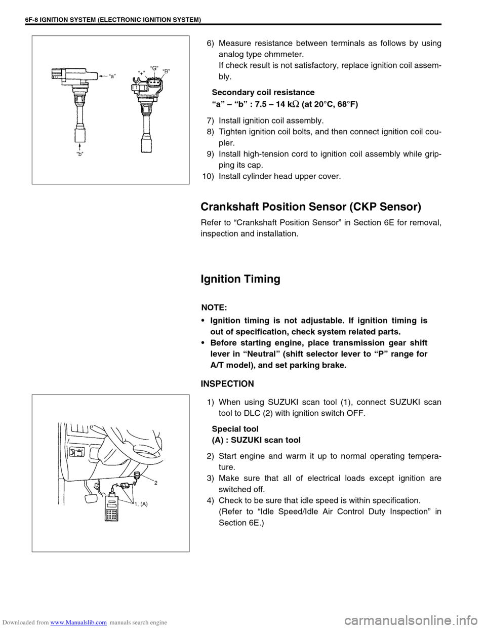
6) Measure resistance between terminals as follows by using
analog type ohmmeter.
If check result is not satisfactory, replace ignition coil assem-
bly.
Secondary coil resistance
“a” – “b” : 7.5 – 14 k
Ω (at 20°C, 68°F)
7) Install ignition coil assembly.
8) Tighten ignition coil bolts, and then connect ignition coil cou-
pler.
9) Install high-tension cord to ignition coil assembly while grip-
ping its cap.
10) Install cylinder head upper cover.
Crankshaft Position Sensor (CKP Sensor)
Refer to “Crankshaft Position Sensor” in Section 6E for removal,
inspection and installation.
Ignition Timing
INSPECTION
1) When using SUZUKI scan tool (1), connect SUZUKI scan
tool to DLC (2) with ignition switch OFF.
Special tool
(A) : SUZUKI scan tool
2) Start engine and warm it up to normal operating tempera-
ture.
3) Make sure that all of electrical loads except ignition are
switched off.
4) Check to be sure that idle speed is within specification.
(Refer to “Idle Speed/Idle Air Control Duty Inspection” in
Section 6E.)
NOTE:
Ignition timing is not adjustable. If ignition timing is
out of specification, check system related parts.
Before starting engine, place transmission gear shift
lever in “Neutral” (shift selector lever to “P” range for
A/T model), and set parking brake.
Page 664 of 687
Downloaded from www.Manualslib.com manuals search engine CRANKING SYSTEM 6G-5
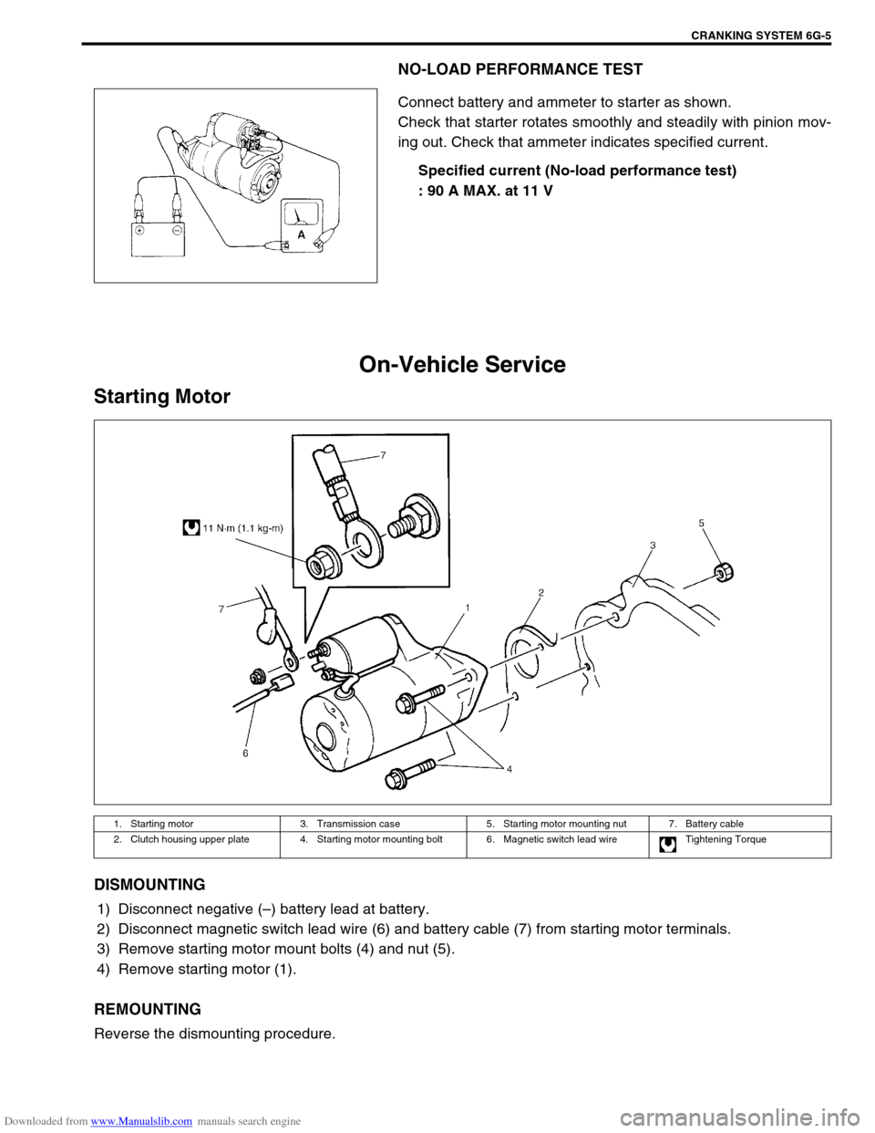
NO-LOAD PERFORMANCE TEST
Connect battery and ammeter to starter as shown.
Check that starter rotates smoothly and steadily with pinion mov-
ing out. Check that ammeter indicates specified current.
Specified current (No-load performance test)
: 90 A MAX. at 11 V
On-Vehicle Service
Starting Motor
DISMOUNTING
1) Disconnect negative (–) battery lead at battery.
2) Disconnect magnetic switch lead wire (6) and battery cable (7) from starting motor terminals.
3) Remove starting motor mount bolts (4) and nut (5).
4) Remove starting motor (1).
REMOUNTING
Reverse the dismounting procedure.
1. Starting motor 3. Transmission case 5. Starting motor mounting nut 7. Battery cable
2. Clutch housing upper plate 4. Starting motor mounting bolt 6. Magnetic switch lead wire Tightening Torque
Page 669 of 687
Downloaded from www.Manualslib.com manuals search engine 6H-2 CHARGING SYSTEM
General Description
Battery
The battery has three major functions in the electrical system.
It is a source of electrical energy for cranking the engine.
It acts as a voltage stabilizer for the electrical system.
It can, for a limited time, provide energy when the electrical
load exceeds the output of the generator.
CARRIER AND HOLD-DOWN
The battery carrier should be in good condition so that it will sup-
port the battery securely and keep it level.
Before installing the battery, the battery carrier and hold-down
clamp should be clean and free from corrosion and make certain
there are no parts in carrier.
To prevent the battery from shaking in its carrier, the hold-down
bolts should be tight enough but not over-tightened.
ELECTROLYTE FREEZING
The freezing point of electrolyte depends on its specific gravity.
Since freezing may ruin a battery, it should be protected against
freezing by keeping it in a fully charged condition. If a battery is
frozen accidentally, it should not be charged until it is warmed.
SULFATION
If the battery is allowed to stand for a long period in discharged
condition, the lead sulfate becomes converted into a hard, crystal-
line substance, which will not easily turn back to the active mate-
rial again during the subsequent recharging. “Sulfation” means
the result as well as the process of that reaction.
Such a battery can be revived by very slow charging and may be
restored to usable condition but its capacity is lower than before.