Downloaded from www.Manualslib.com manuals search engine 6A1-68 ENGINE MECHANICAL (M13 ENGINE)
Rod bearing :
Inspect bearing shells for signs of fusion, pitting, burn or flak-
ing and observe contact pattern. Bearing shells found in
defective condition must be replaced.
Two kinds of rod bearing are available; standard size bear-
ing and 0.25 mm (0.0098 in.) undersize bearing. For identifi-
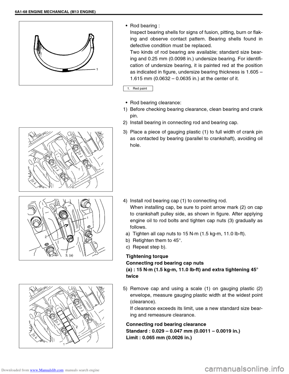
cation of undersize bearing, it is painted red at the position
as indicated in figure, undersize bearing thickness is 1.605 –
1.615 mm (0.0632 – 0.0635 in.) at the center of it.
Rod bearing clearance:
1) Before checking bearing clearance, clean bearing and crank
pin.
2) Install bearing in connecting rod and bearing cap.
3) Place a piece of gauging plastic (1) to full width of crank pin
as contacted by bearing (parallel to crankshaft), avoiding oil
hole.
4) Install rod bearing cap (1) to connecting rod.
When installing cap, be sure to point arrow mark (2) on cap
to crankshaft pulley side, as shown in figure. After applying
engine oil to rod bolts and tighten cap nuts (3) gradually as
follows.
a) Tighten all cap nuts to 15 N·m (1.5 kg-m, 11.0 lb-ft).
b) Retighten them to 45°.
c) Repeat step b).
Tightening torque
Connecting rod bearing cap nuts
(a) : 15 N·m (1.5 kg-m, 11.0 lb-ft) and extra tightening 45°
twice
5) Remove cap and using a scale (1) on gauging plastic (2)
envelope, measure gauging plastic width at the widest point
(clearance).
If clearance exceeds its limit, use a new standard size bear-
ing and remeasure clearance.
Connecting rod bearing clearance
Standard : 0.029 – 0.047 mm (0.0011 – 0.0019 in.)
Limit : 0.065 mm (0.0026 in.)
1. Red paint
