turn SUZUKI JIMNY 2005 3.G Service Workshop Manual
[x] Cancel search | Manufacturer: SUZUKI, Model Year: 2005, Model line: JIMNY, Model: SUZUKI JIMNY 2005 3.GPages: 687, PDF Size: 13.38 MB
Page 518 of 687
Downloaded from www.Manualslib.com manuals search engine ENGINE MECHANICAL (M13 ENGINE) 6A1-37
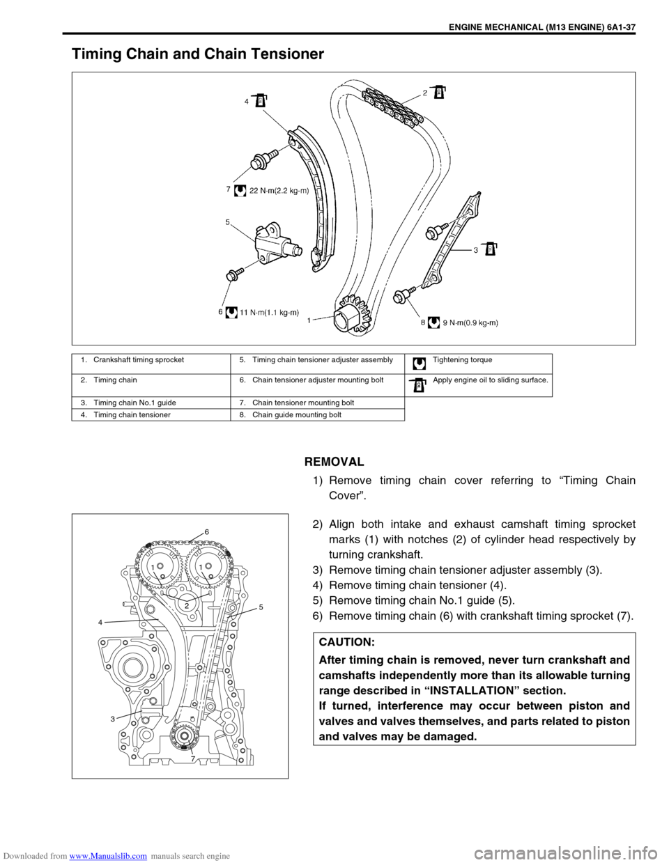
Timing Chain and Chain Tensioner
REMOVAL
1) Remove timing chain cover referring to “Timing Chain
Cover”.
2) Align both intake and exhaust camshaft timing sprocket
marks (1) with notches (2) of cylinder head respectively by
turning crankshaft.
3) Remove timing chain tensioner adjuster assembly (3).
4) Remove timing chain tensioner (4).
5) Remove timing chain No.1 guide (5).
6) Remove timing chain (6) with crankshaft timing sprocket (7).
1. Crankshaft timing sprocket 5. Timing chain tensioner adjuster assembly Tightening torque
2. Timing chain 6. Chain tensioner adjuster mounting bolt Apply engine oil to sliding surface.
3. Timing chain No.1 guide 7. Chain tensioner mounting bolt
4. Timing chain tensioner 8. Chain guide mounting bolt
CAUTION:
After timing chain is removed, never turn crankshaft and
camshafts independently more than its allowable turning
range described in “INSTALLATION” section.
If turned, interference may occur between piston and
valves and valves themselves, and parts related to piston
and valves may be damaged.
45
6
21
1
3
7
Page 520 of 687
Downloaded from www.Manualslib.com manuals search engine ENGINE MECHANICAL (M13 ENGINE) 6A1-39
INSTALLATION
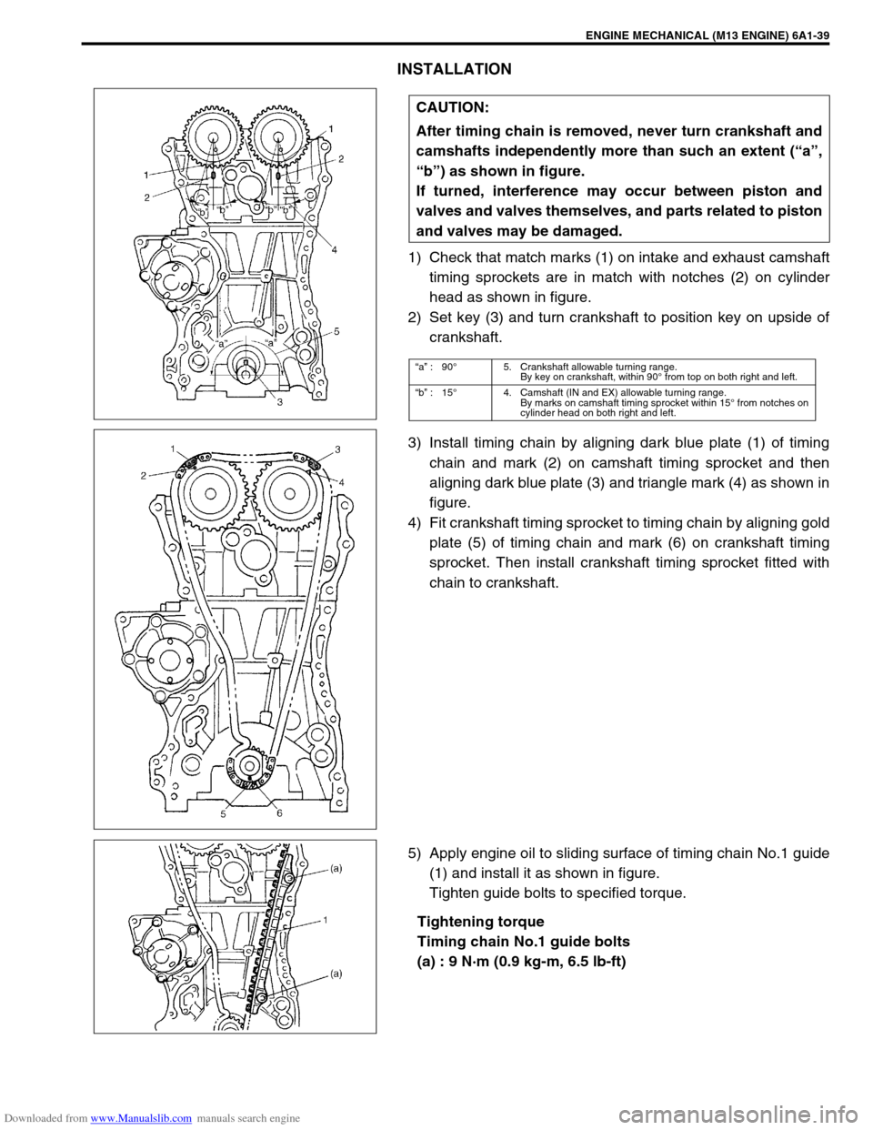
1) Check that match marks (1) on intake and exhaust camshaft
timing sprockets are in match with notches (2) on cylinder
head as shown in figure.
2) Set key (3) and turn crankshaft to position key on upside of
crankshaft.
3) Install timing chain by aligning dark blue plate (1) of timing
chain and mark (2) on camshaft timing sprocket and then
aligning dark blue plate (3) and triangle mark (4) as shown in
figure.
4) Fit crankshaft timing sprocket to timing chain by aligning gold
plate (5) of timing chain and mark (6) on crankshaft timing
sprocket. Then install crankshaft timing sprocket fitted with
chain to crankshaft.
5) Apply engine oil to sliding surface of timing chain No.1 guide
(1) and install it as shown in figure.
Tighten guide bolts to specified torque.
Tightening torque
Timing chain No.1 guide bolts
(a) : 9 N·m (0.9 kg-m, 6.5 lb-ft) CAUTION:
After timing chain is removed, never turn crankshaft and
camshafts independently more than such an extent (“a”,
“b”) as shown in figure.
If turned, interference may occur between piston and
valves and valves themselves, and parts related to piston
and valves may be damaged.
“a” :90°5. Crankshaft allowable turning range.
By key on crankshaft, within 90° from top on both right and left.
“b” :15°4. Camshaft (IN and EX) allowable turning range.
By marks on camshaft timing sprocket within 15° from notches on
cylinder head on both right and left.
Page 521 of 687
Downloaded from www.Manualslib.com manuals search engine 6A1-40 ENGINE MECHANICAL (M13 ENGINE)
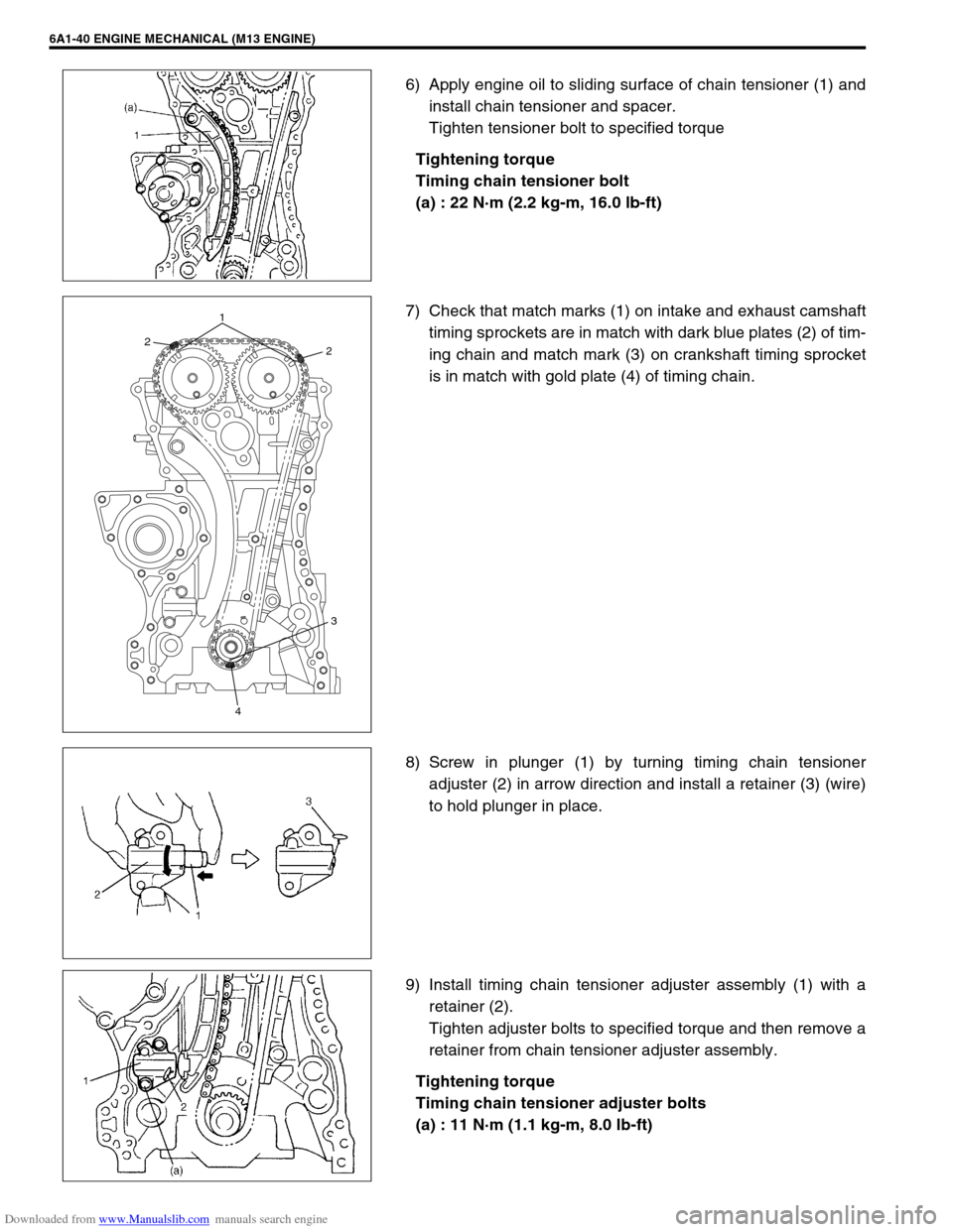
6) Apply engine oil to sliding surface of chain tensioner (1) and
install chain tensioner and spacer.
Tighten tensioner bolt to specified torque
Tightening torque
Timing chain tensioner bolt
(a) : 22 N·m (2.2 kg-m, 16.0 lb-ft)
7) Check that match marks (1) on intake and exhaust camshaft
timing sprockets are in match with dark blue plates (2) of tim-
ing chain and match mark (3) on crankshaft timing sprocket
is in match with gold plate (4) of timing chain.
8) Screw in plunger (1) by turning timing chain tensioner
adjuster (2) in arrow direction and install a retainer (3) (wire)
to hold plunger in place.
9) Install timing chain tensioner adjuster assembly (1) with a
retainer (2).
Tighten adjuster bolts to specified torque and then remove a
retainer from chain tensioner adjuster assembly.
Tightening torque
Timing chain tensioner adjuster bolts
(a) : 11 N·m (1.1 kg-m, 8.0 lb-ft)
221
3
4
Page 522 of 687
Downloaded from www.Manualslib.com manuals search engine ENGINE MECHANICAL (M13 ENGINE) 6A1-41
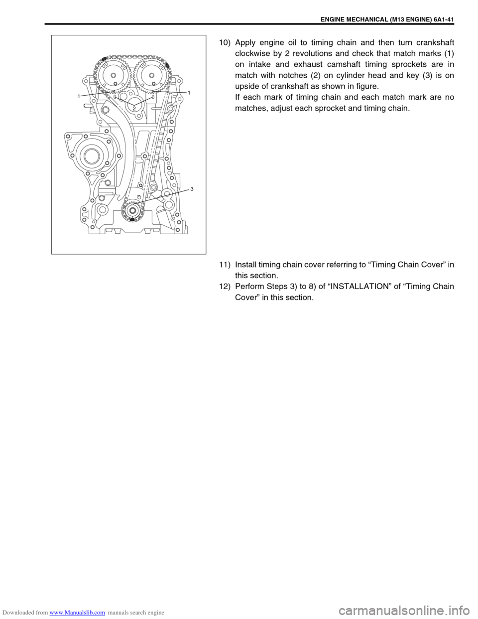
10) Apply engine oil to timing chain and then turn crankshaft
clockwise by 2 revolutions and check that match marks (1)
on intake and exhaust camshaft timing sprockets are in
match with notches (2) on cylinder head and key (3) is on
upside of crankshaft as shown in figure.
If each mark of timing chain and each match mark are no
matches, adjust each sprocket and timing chain.
11) Install timing chain cover referring to “Timing Chain Cover” in
this section.
12) Perform Steps 3) to 8) of “INSTALLATION” of “Timing Chain
Cover” in this section.
21
1
3
Page 527 of 687
Downloaded from www.Manualslib.com manuals search engine 6A1-46 ENGINE MECHANICAL (M13 ENGINE)
INSTALLATION
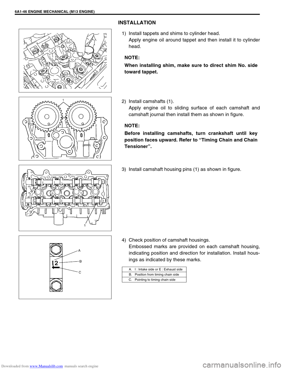
1) Install tappets and shims to cylinder head.
Apply engine oil around tappet and then install it to cylinder
head.
2) Install camshafts (1).
Apply engine oil to sliding surface of each camshaft and
camshaft journal then install them as shown in figure.
3) Install camshaft housing pins (1) as shown in figure.
4) Check position of camshaft housings.
Embossed marks are provided on each camshaft housing,
indicating position and direction for installation. Install hous-
ings as indicated by these marks. NOTE:
When installing shim, make sure to direct shim No. side
toward tappet.
NOTE:
Before installing camshafts, turn crankshaft until key
position faces upward. Refer to “Timing Chain and Chain
Tensioner”.
A. I : Intake side or E : Exhaust side
B. Position from timing chain side
C. Pointing to timing chain side
Page 529 of 687
Downloaded from www.Manualslib.com manuals search engine 6A1-48 ENGINE MECHANICAL (M13 ENGINE)
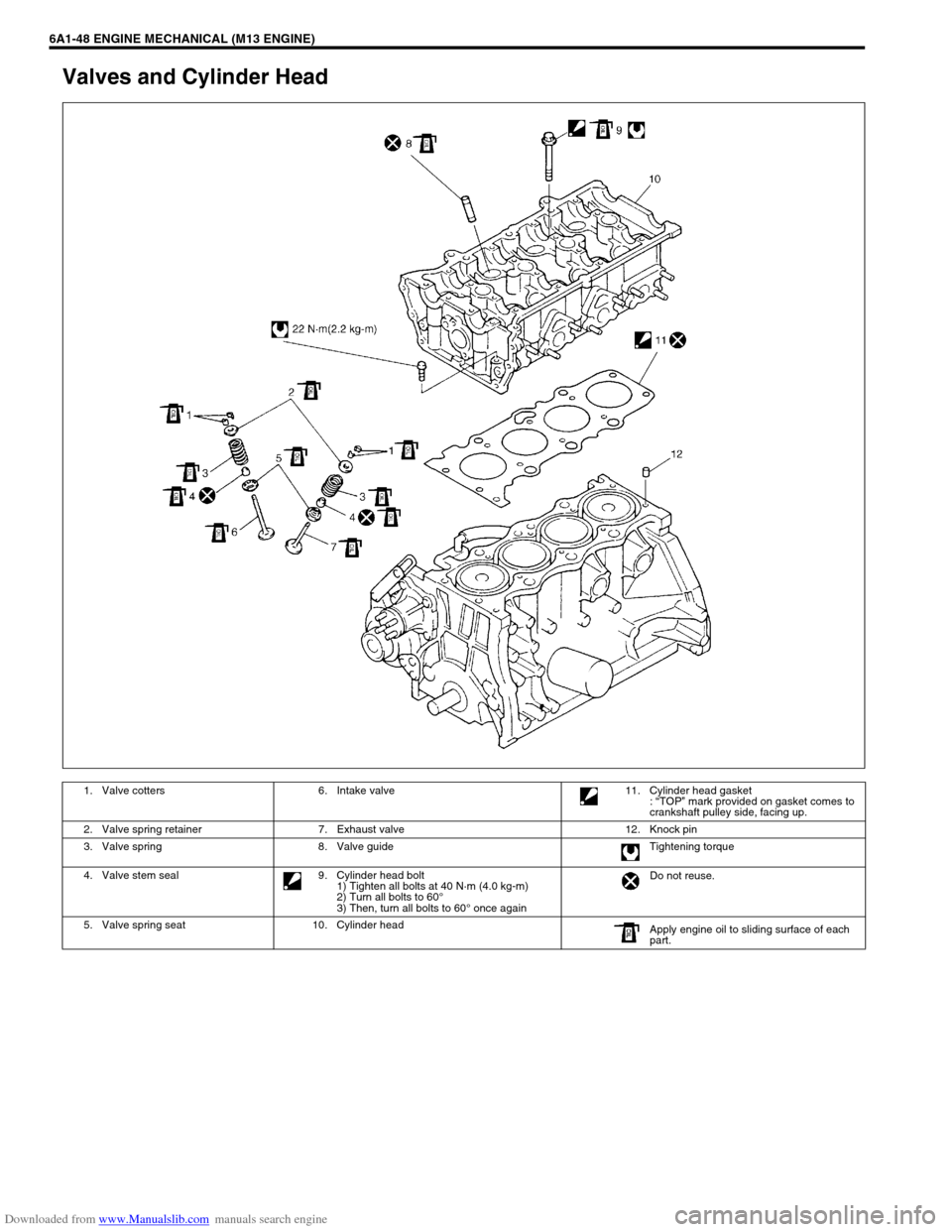
Valves and Cylinder Head
1. Valve cotters 6. Intake valve 11. Cylinder head gasket
: “TOP” mark provided on gasket comes to
crankshaft pulley side, facing up.
2. Valve spring retainer 7. Exhaust valve 12. Knock pin
3. Valve spring 8. Valve guide Tightening torque
4. Valve stem seal 9. Cylinder head bolt
1) Tighten all bolts at 40 N·m (4.0 kg-m)
2) Turn all bolts to 60°
3) Then, turn all bolts to 60° once againDo not reuse.
5. Valve spring seat 10. Cylinder head
Apply engine oil to sliding surface of each
part.
Page 531 of 687
Downloaded from www.Manualslib.com manuals search engine 6A1-50 ENGINE MECHANICAL (M13 ENGINE)
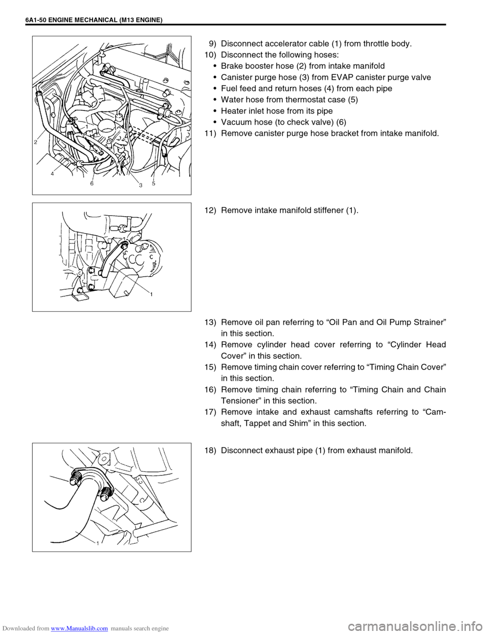
9) Disconnect accelerator cable (1) from throttle body.
10) Disconnect the following hoses:
Brake booster hose (2) from intake manifold
Canister purge hose (3) from EVAP canister purge valve
Fuel feed and return hoses (4) from each pipe
Water hose from thermostat case (5)
Heater inlet hose from its pipe
Vacuum hose (to check valve) (6)
11) Remove canister purge hose bracket from intake manifold.
12) Remove intake manifold stiffener (1).
13) Remove oil pan referring to “Oil Pan and Oil Pump Strainer”
in this section.
14) Remove cylinder head cover referring to “Cylinder Head
Cover” in this section.
15) Remove timing chain cover referring to “Timing Chain Cover”
in this section.
16) Remove timing chain referring to “Timing Chain and Chain
Tensioner” in this section.
17) Remove intake and exhaust camshafts referring to “Cam-
shaft, Tappet and Shim” in this section.
18) Disconnect exhaust pipe (1) from exhaust manifold.
Page 543 of 687
Downloaded from www.Manualslib.com manuals search engine 6A1-62 ENGINE MECHANICAL (M13 ENGINE)
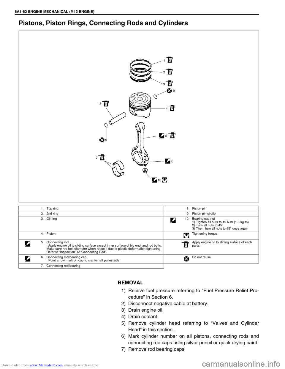
Pistons, Piston Rings, Connecting Rods and Cylinders
REMOVAL
1) Relieve fuel pressure referring to “Fuel Pressure Relief Pro-
cedure” in Section 6.
2) Disconnect negative cable at battery.
3) Drain engine oil.
4) Drain coolant.
5) Remove cylinder head referring to “Valves and Cylinder
Head” in this section.
6) Mark cylinder number on all pistons, connecting rods and
connecting rod caps using silver pencil or quick drying paint.
7) Remove rod bearing caps.
1. Top ring8. Piston pin
2. 2nd ring9. Piston pin circlip
3. Oil ring10. Bearing cap nut
1) Tighten all nuts to 15 N·m (1.5 kg-m)
2) Turn all nuts to 45°
3) Then, turn all nuts to 45° once again
4. PistonTightening torque
5. Connecting rod
: Apply engine oil to sliding surface except inner surface of big end, and rod bolts.
Make sure rod bolt diameter when reuse it due to plastic deformation tightening.
Refer to “Inspection” of “Connecting Rod”.Apply engine oil to sliding surface of each
parts.
6. Connecting rod bearing cap
: Point arrow mark on cap to crankshaft pulley side.Do not reuse.
7. Connecting rod bearing
Page 556 of 687
Downloaded from www.Manualslib.com manuals search engine ENGINE MECHANICAL (M13 ENGINE) 6A1-75
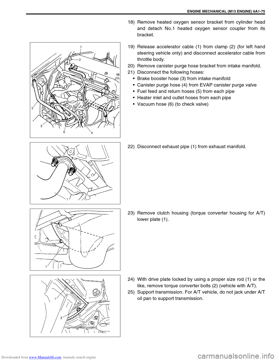
18) Remove heated oxygen sensor bracket from cylinder head
and detach No.1 heated oxygen sensor coupler from its
bracket.
19) Release accelerator cable (1) from clamp (2) (for left hand
steering vehicle only) and disconnect accelerator cable from
throttle body.
20) Remove canister purge hose bracket from intake manifold.
21) Disconnect the following hoses:
Brake booster hose (3) from intake manifold
Canister purge hose (4) from EVAP canister purge valve
Fuel feed and return hoses (5) from each pipe
Heater inlet and outlet hoses from each pipe
Vacuum hose (6) (to check valve)
22) Disconnect exhaust pipe (1) from exhaust manifold.
23) Remove clutch housing (torque converter housing for A/T)
lower plate (1).
24) With drive plate locked by using a proper size rod (1) or the
like, remove torque converter bolts (2) (vehicle with A/T).
25) Support transmission. For A/T vehicle, do not jack under A/T
oil pan to support transmission.
Page 560 of 687
Downloaded from www.Manualslib.com manuals search engine ENGINE MECHANICAL (M13 ENGINE) 6A1-79
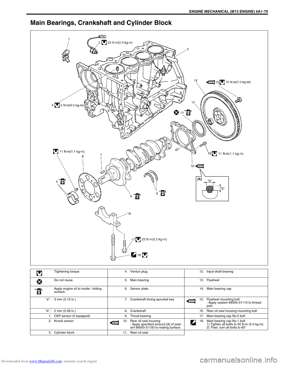
Main Bearings, Crankshaft and Cylinder Block
Tightening torque 4. Venturi plug 12. Input shaft bearing
Do not reuse. 5. Main bearing 13. Flywheel
Apply engine oil to inside / sliding
surface.6. Sensor plate 14. Main bearing cap
“a” : 3 mm (0.12 in.) 7. Crankshaft timing sprocket key 15. Flywheel mounting bolt
: Apply sealant 99000-31110 to thread
part.
“b” : 2 mm (0.08 in.) 8. Crankshaft 16. Rear oil seal housing mounting bolt
1. CKP sensor (if equipped) 9. Thrust bearing 17. Main bearing cap No.2 bolt
2. Knock sensor 10. Rear oil seal housing
: Apply specified amount [A] of seal-
ant 99000-31150 to mating surface. 18. Main bearing cap No.1 bolt
1) Tighten all bolts to 50 N·m (5.0 kg-m)
2) Then, turn all bolts to 60°
3. Cylinder block 11. Rear oil seal